Cisco Intrusion Prevention System Appliance and Module Installation Guide for IPS 5.1
Bias-Free Language
The documentation set for this product strives to use bias-free language. For the purposes of this documentation set, bias-free is defined as language that does not imply discrimination based on age, disability, gender, racial identity, ethnic identity, sexual orientation, socioeconomic status, and intersectionality. Exceptions may be present in the documentation due to language that is hardcoded in the user interfaces of the product software, language used based on RFP documentation, or language that is used by a referenced third-party product. Learn more about how Cisco is using Inclusive Language.
- Updated:
- November 17, 2006
Chapter: Installing AIP-SSM
Installing AIP-SSM
This chapter describes how to install AIP-SSM. It contains the following sections:
•![]() Hardware and Software Requirements
Hardware and Software Requirements
•![]() Installation and Removal Instructions
Installation and Removal Instructions
Specifications
Table 7-1 lists the specifications for AIP-SSM:
|
|
|
|---|---|
Dimensions (H x W x D) |
1.70 x 6.80 x 11.00 inches |
Weight |
Minimum: 2.50 lb |
Operating temperature |
+32° to +104°F (+0° to +40°C) |
Nonoperating temperature |
-40° to +167°F (-40° to +75°C) |
Humidity |
10% to 90%, noncondensing |
1 2.70 lbs for 45 c heatsink, approximately 3.00 lbs for the 55c maximum |
Memory Specifications
Table 7-2 lists the memory specifications for AIP-SSM.
|
|
|
|
|---|---|---|
ASA-SSM-AIP-10-K9 |
2.0 GHz Celeron |
1.0 GB |
ASA-SSM-AIP-20-K9 |
2.4 GHz Pentium 4 |
2.0 GB |
Hardware and Software Requirements
AIP-SSM has the following hardware and software requirements:
•![]() Cisco ASA 5500 series adaptive security appliance
Cisco ASA 5500 series adaptive security appliance
–![]() ASA 5510 (ASA-SSM-AIP-10-K9 and ASA-SSM-AIP-20-K9)
ASA 5510 (ASA-SSM-AIP-10-K9 and ASA-SSM-AIP-20-K9)
–![]() ASA 5520 (ASA-SSM-AIP-10-K9 and ASA-SSM-AIP-20-K9)
ASA 5520 (ASA-SSM-AIP-10-K9 and ASA-SSM-AIP-20-K9)
–![]() ASA 5540 (ASA-SSM-AIP-20-K9)
ASA 5540 (ASA-SSM-AIP-20-K9)
•![]() Cisco Adaptive Security Appliance Software 7.0 or higher
Cisco Adaptive Security Appliance Software 7.0 or higher
•![]() Cisco Intrusion Prevention System Software 5.0(2) or higher
Cisco Intrusion Prevention System Software 5.0(2) or higher
•![]() DES or 3DES-enabled
DES or 3DES-enabled
Indicators
Figure 7-1 shows the AIP-SSM indicators.
Figure 7-1 AIP-SSM Indicators
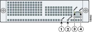
Table 7-3 describes the AIP-SSM indicators.
Installation and Removal Instructions
This section describes how to install and remove AIP-SSM, and contains the following topics:
•![]() Verifying the Status of AIP-SSM
Verifying the Status of AIP-SSM
Installing AIP-SSM
To install AIP-SSM, follow these steps:
Step 1 ![]() Power off ASA.
Power off ASA.
Step 2 ![]() Locate the grounding strap from the accessory kit and fasten it to your wrist so that it contacts your bare skin. Attach the other end to the chassis.
Locate the grounding strap from the accessory kit and fasten it to your wrist so that it contacts your bare skin. Attach the other end to the chassis.
For more information, see Working in an ESD Environment.
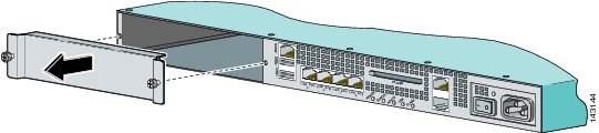
Step 3 ![]() Remove the two screws at the left back end of the chassis, and remove the slot cover.
Remove the two screws at the left back end of the chassis, and remove the slot cover.
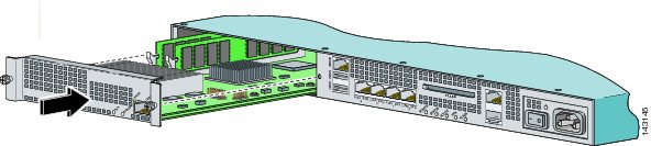
Step 4 ![]() Insert AIP-SSM through the slot opening.
Insert AIP-SSM through the slot opening.
Step 5 ![]() Attach the screws to secure AIP-SSM to the chassis.
Attach the screws to secure AIP-SSM to the chassis.
Step 6 ![]() Power on ASA by pushing the power switch at the back of the chassis.
Power on ASA by pushing the power switch at the back of the chassis.
Step 7 ![]() Check the indicators.
Check the indicators.
If AIP-SSM is properly installed, the POWER indicator is solid green and the STATUS indicator is flashing green. You can also verify that AIP-SSM is online using the show module command. For the procedure, see Verifying the Status of AIP-SSM.
Step 8 ![]() Initialize AIP-SSM.
Initialize AIP-SSM.
For the procedure, see Initializing the Sensor.
Step 9 ![]() Install the most recent Cisco IPS software.
Install the most recent Cisco IPS software.
For the procedure, see Obtaining Cisco IPS Software.
Step 10 ![]() Configure AIP-SSM to receive IPS traffic.
Configure AIP-SSM to receive IPS traffic.
For the procedure, refer to Sending Traffic to AIP-SSM.
For More Information
•![]() For the procedure for using HTTPS to log in to IDM and ASDM, refer to Logging In to IDM.
For the procedure for using HTTPS to log in to IDM and ASDM, refer to Logging In to IDM.
•![]() For the procedures for configuring intrusion prevention on your sensor, refer to the following documents:
For the procedures for configuring intrusion prevention on your sensor, refer to the following documents:
–![]() Installing and Using Cisco Intrusion Prevention System Device Manager 5.1
Installing and Using Cisco Intrusion Prevention System Device Manager 5.1
–![]() Configuring the Cisco Intrusion Prevention System Sensor Using the Command Line Interface 5.1
Configuring the Cisco Intrusion Prevention System Sensor Using the Command Line Interface 5.1
Verifying the Status of AIP-SSM
You can use the show module 1 command to verify that AIP-SSM is up and running.
To verify the status of AIP-SSM, follow these steps:
Step 1 ![]() Log in to ASA.
Log in to ASA.
Step 2 ![]() Verify the status of AIP-SSM:
Verify the status of AIP-SSM:
asa# show module 1
Mod Card Type Model Serial No.
--- -------------------------------------------- ------------------ -----------
1 ASA 5500 Series Security Services Module-20 ASA-SSM-20 P2B000005D0
Mod MAC Address Range Hw Version Fw Version Sw Version
--- --------------------------------- ------------ ------------ ---------------
1 000b.fcf8.0144 to 000b.fcf8.0144 0.2 1.0(9)0 5.0(0.27)S129.0
Mod Status
--- ------------------
1 Up
asa#
If the status reads Up, AIP-SSM has been properly installed.
The following values are valid for the Status field:
•![]()
Initializing—AIP-SSM is being detected and the control communication is being initialized by the system.
•![]()
Up—AIP-SSM has completed initialization by the system.
•![]()
Unresponsive—The system encountered an error communicating with AIP-SSM.
•![]()
Reloading—AIP-SSM is reloading.
•![]()
Shutting Down—AIP-SSM is shutting down.
•![]()
Down—AIP-SSM is shut down.
•![]()
Recover—AIP-SSM is attempting to download a recovery image.
Removing AIP-SSM
To remove AIP-SSM, follow these steps:
Step 1 ![]() Shut down AIP-SSM:
Shut down AIP-SSM:
asa# hw-module module 1 shutdown
Shutdown module in slot 1? [confirm]
Step 2 ![]() Press Enter to confirm.
Press Enter to confirm.
Step 3 ![]() Verify if AIP-SSM is down by checking the indicators.
Verify if AIP-SSM is down by checking the indicators.
Step 4 ![]() Power off ASA.
Power off ASA.
Step 5 ![]() Locate the grounding strap from the accessory kit and fasten it to your wrist so that it contacts your bare skin. Attach the other end to the chassis.
Locate the grounding strap from the accessory kit and fasten it to your wrist so that it contacts your bare skin. Attach the other end to the chassis.
For more information, see Working in an ESD Environment.
Step 6 ![]() Remove the two screws at the left back end of the chassis, and remove the slot cover.
Remove the two screws at the left back end of the chassis, and remove the slot cover.
Step 7 ![]() Remove AIP-SSM and set it aside.
Remove AIP-SSM and set it aside.
Step 8 ![]() If you need to replace the existing AIP-SSM, insert the new AIP-SSM through the slot opening.
If you need to replace the existing AIP-SSM, insert the new AIP-SSM through the slot opening.

Note ![]() Do not replace AIP-SSM with a different model. The ASA will not recognize it.
Do not replace AIP-SSM with a different model. The ASA will not recognize it.
Step 9 ![]() Attach the screws to secure AIP-SSM to the chassis.
Attach the screws to secure AIP-SSM to the chassis.
Step 10 ![]() Power on ASA.
Power on ASA.
Step 11 ![]() Reset AIP-SSM:
Reset AIP-SSM:
asa# hw-module module 1 reset
Reset module in slot 1? [confirm]
Step 12 ![]() Press Enter to confirm.
Press Enter to confirm.
Step 13 ![]() Check the indicators to see if AIP-SSM is properly installed.
Check the indicators to see if AIP-SSM is properly installed.
If AIP-SSM is properly installed, the POWER indicator is solid green and the STATUS indicator is flashing green. Or you can verify installation using the show module command. For the procedure, see Verifying the Status of AIP-SSM.
 Feedback