Cisco Intrusion Prevention System Appliance and Module Installation Guide for IPS 5.1
Bias-Free Language
The documentation set for this product strives to use bias-free language. For the purposes of this documentation set, bias-free is defined as language that does not imply discrimination based on age, disability, gender, racial identity, ethnic identity, sexual orientation, socioeconomic status, and intersectionality. Exceptions may be present in the documentation due to language that is hardcoded in the user interfaces of the product software, language used based on RFP documentation, or language that is used by a referenced third-party product. Learn more about how Cisco is using Inclusive Language.
- Updated:
- November 17, 2006
Chapter: Installing IPS-4260
Installing IPS-4260
This chapter describes IPS-4260 and how to install it. It also describes the accessories and how to install them. This chapter contains the following sections:
•![]() Front and Back Panel Features
Front and Back Panel Features
•![]() Removing and Replacing the Chassis Cover
Removing and Replacing the Chassis Cover
•![]() Installing and Removing PCI Cards
Installing and Removing PCI Cards
•![]() Installing and Removing the Power Supply
Installing and Removing the Power Supply

Introducing IPS-4260
IPS-4260 delivers 1 Gigabit of intrusion prevention performance. You can use IPS-4260 to protect both Gigabit subnets and aggregated traffic traversing switches from multiple subnets. IPS-4260 is a purpose-built device that provides support for both copper and fiber NIC environments providing flexibility of deployment in any environment.
IPS-4260 has two built-in Gigabit Ethernet network ports and six expansion slots. The network port numbers increase from right to left and the expansion slot numbers increase from bottom to top and from right to left as shown in Figure 5-4. Slots 2 and 3 are PCI-Express connectors and the other expansion slots are PCI-X slots. Slots 1 through 3 are full-height slots and slots 4 though 6 are half-height slots. The built-in management port is called Management0/0 and the built-in sensing interface is Gigabit-Ethernet0/1. For more information on sensor interfaces, see Sensor Interfaces.

Note ![]() Only expansion slots 2 and 3 are supported at this time.
Only expansion slots 2 and 3 are supported at this time.
For improved reliability, IPS-4260 uses a flash device for storage rather than a hard-disk drive. IPS-4260 supports two optional network interface cards, the 2SX Fiber card, and the 4GE bypass interface card that contains the hardware-bypass feature. Initially IPS-4260 supports only the built-in interfaces and these two interface cards. For more information on the 4GE bypass interface card, see Hardware Bypass.
IPS-4260 monitors greater than 1 Gbps of aggregate network traffic on multiple sensing interfaces and is also inline ready. It replaces IDS-4250-XL. It supports both copper and fiber interfaces.
Note ![]() The 1-Gbps performance for IPS-4260 is based on the following conditions: 10,000 new TCP connections per second, 100,000 HTTP transactions per second, average packet size of 450 bytes, and the system running Cisco IPS 5.1 software. The 1-Gbps performance is traffic combined from all sensing interfaces.
The 1-Gbps performance for IPS-4260 is based on the following conditions: 10,000 new TCP connections per second, 100,000 HTTP transactions per second, average packet size of 450 bytes, and the system running Cisco IPS 5.1 software. The 1-Gbps performance is traffic combined from all sensing interfaces.
IPS-4260 ships with one power supply, but it supports redundant power supplies. For more information, see Installing and Removing the Power Supply.
Note ![]() IPS-4260 operates in load-sharing mode when the optional redundant power supply is installed.
IPS-4260 operates in load-sharing mode when the optional redundant power supply is installed.
Supported PCI Cards
IPS-4260 supports the following PCI cards:
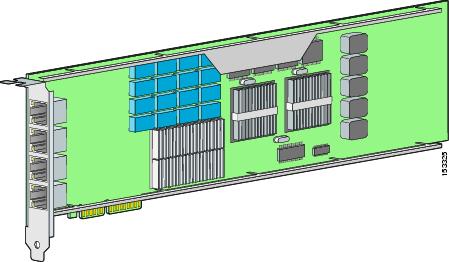
•![]() 4GE bypass interface card (part number IPS-4GE-BP-INT=)
4GE bypass interface card (part number IPS-4GE-BP-INT=)
Provides four 10/100/1000BASE-T (4GE) monitoring interfaces (allowing up to 9 total monitoring interfaces). The 4GE bypass interface card support hardware bypass.
Figure 5-1 shows the 4GE bypass interface card.
Figure 5-1 4GE Bypass Interface Card
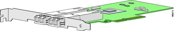
•![]() 2SX Card (part number IPS-2SX-INT=)
2SX Card (part number IPS-2SX-INT=)
Provides two 1000BASE-SX (fiber) monitoring interfaces (allowing up to 4 total fiber monitoring interfaces). The 2SX interface cards does not support hardware bypass.
Figure 5-2 shows the 2SX card.
Figure 5-2 2SX Interface Card
Hardware Bypass
This section describes the 4GE bypass interface card and its configuration restrictions. For the procedure for installing and removing the 4GE bypass interface card, see Installing and Removing PCI Cards.
This section contains the following topics:
•![]() Hardware Bypass Configuration Restrictions
Hardware Bypass Configuration Restrictions
4GE Bypass Interface card
IPS-4260 supports the 4-port GigabitEthernet card (part number IPS-4GE-BP-INT=) with hardware bypass. This 4GE bypass interface card supports hardware bypass only between ports 0 and 1 and between ports 2 and 3. Figure 5-1 shows the 4GE bypass interface card.
Hardware bypass complements the existing software bypass feature in IPS 5.1. For more information on software bypass mode, refer to Configuring Bypass Mode. The following conditions apply to hardware bypass and software bypass on IPS-4260:
•![]() When bypass is set to OFF, software bypass is not active.
When bypass is set to OFF, software bypass is not active.
For each inline interface for which hardware bypass is available, the component interfaces are set to disable the fail-open capability. If SensorApp fails, the sensor is powered off, reset, or if the NIC interface drivers fail or are unloaded, the paired interfaces enter the fail-closed state (no traffic flows through inline interface or inline VLAN subinterfaces).
•![]() When bypass is set to ON, software bypass is active.
When bypass is set to ON, software bypass is active.
Software bypass forwards packets between the paired physical interfaces in each inline interface and between the paired VLANs in each inline VLAN subinterface. For each inline interface on which hardware bypass is available, the component interfaces are set to standby mode. If the sensor is powered off, reset, or if the NIC interfaces fail or are unloaded, those paired interfaces enter fail-open state in hardware (traffic flows unimpeded through inline interface). Any other inline interfaces enter fail-closed state.
•![]() When bypass is set to AUTO (traffic flows without inspection), software bypass is activated if sensorApp fails.
When bypass is set to AUTO (traffic flows without inspection), software bypass is activated if sensorApp fails.
For each inline interface on which hardware bypass is available, the component interfaces are set to standby mode. If the sensor is powered off, reset, or if the NIC interfaces fail or are unloaded, those paired interfaces enter fail-open state in hardware. Any other inline interfaces enter the fail-closed state.
Note ![]() To test fail-over, set the bypass mode to ON or AUTO, create one or more inline interfaces and power down the sensor and verify that traffic still flows through the inline path.
To test fail-over, set the bypass mode to ON or AUTO, create one or more inline interfaces and power down the sensor and verify that traffic still flows through the inline path.
Hardware Bypass Configuration Restrictions
To use the hardware bypass feature on the 4GE bypass interface card, you must pair interfaces to support the hardware design of the card. If you create an inline interface that pairs a hardware-bypass-capable interface with an interface that violates one or more of the hardware-bypass configuration restrictions, hardware bypass is deactivated on the inline interface and you receive a warning message similar to the following:
Hardware bypass functionality is not available on Inline-interface pair0.
Physical-interface GigabitEthernet2/0 is capable of performing hardware bypass only when
paired with GigabitEthernet2/1, and both interfaces are enabled and configured with the
same speed and duplex settings.
The following configuration restrictions apply to hardware bypass:
•![]() The 4-port bypass card is only supported on IPS-4260.
The 4-port bypass card is only supported on IPS-4260.
•![]() Fail-open hardware bypass only works on inline interfaces (interface pairs), not on inline VLAN pairs.
Fail-open hardware bypass only works on inline interfaces (interface pairs), not on inline VLAN pairs.
•![]() Fail-open hardware bypass is available on an inline interface if all of the following conditions are met:
Fail-open hardware bypass is available on an inline interface if all of the following conditions are met:
–![]() Both of the physical interfaces support hardware bypass.
Both of the physical interfaces support hardware bypass.
–![]() Both of the physical interfaces are on the same interface card.
Both of the physical interfaces are on the same interface card.
–![]() The two physical interfaces are associated in hardware as a bypass pair.
The two physical interfaces are associated in hardware as a bypass pair.
–![]() The speed and duplex settings are identical on the physical interfaces.
The speed and duplex settings are identical on the physical interfaces.
–![]() Both of the interfaces are administratively enabled.
Both of the interfaces are administratively enabled.
•![]() Autonegotiation must be set on MDI/X switch ports connected to IPS-4260.
Autonegotiation must be set on MDI/X switch ports connected to IPS-4260.
You must configure both the sensor ports and the switch ports for autonegotiation for hardware bypass to work. The switch ports must support MDI/X, which automatically reverses the transmit and receive lines if necessary to correct any cabling problems. The sensor is only guaranteed to operate correctly with the switch if both of them are configured for identical speed and duplex, which means that the sensor must be set for autonegotiation too.
Front and Back Panel Features
This section describes the IPS-4260 front and back panel features and indicators.
Figure 5-3 shows the front view of IPS-4260.
Figure 5-3 IPS-4260 Front Panel Features
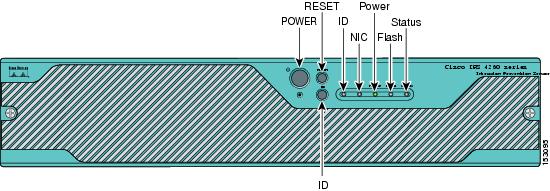
There are three switches on the front panel of IPS-4260:
•![]() Power—Toggles the system power.
Power—Toggles the system power.
•![]() Reset—Resets the system.
Reset—Resets the system.
•![]() ID—Toggles the system ID indicator.
ID—Toggles the system ID indicator.
Table 5-1 describes the front panel indicators on IPS-4260.
Figure 5-4 shows the back view of the IPS-4260.
Figure 5-4 IPS-4260 Back Panel Features
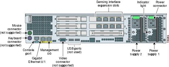
Figure 5-5 shows the two built-in Ethernet ports, which have two indicators per port.
Figure 5-5 Ethernet Port Indicators
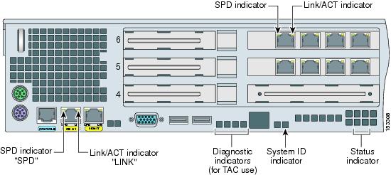
Table 5-2 lists the back panel indicators.
|
|
|
|
|---|---|---|
Left side |
Green solid |
Physical link |
Right side |
Not lit |
10 Mbps |
Table 5-3 lists the power supply indicator.
Specifications
Table 5-4 lists the specifications for IPS-4260.
Accessories
 |
Warning |
IPS-4260 accessories kit contains the following:
•![]() DB25 connector
DB25 connector
•![]() DB9 connector
DB9 connector
•![]() Rack mounting kit—screws, washers, and metal bracket
Rack mounting kit—screws, washers, and metal bracket
•![]() RJ45 console cable
RJ45 console cable
•![]() Two 6-ft Ethernet cables
Two 6-ft Ethernet cables
Rack Mounting
You can rack mount IPS-4260 in a 2- or 4-post rack. This section describes how to rack mount IPS-4260 and contains the following topics:
•![]() Installing IPS-4260 in a 4-Post Rack
Installing IPS-4260 in a 4-Post Rack
•![]() Installing IPS-4260 in a 2-Post Rack
Installing IPS-4260 in a 2-Post Rack
Installing IPS-4260 in a 4-Post Rack
To rack mount IPS-4260 in a 4-post rack, follow these steps:
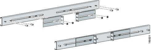
Step 1 ![]() Attach each inner rail to each side of the chassis with three 8-32x1/4" SEMS screws.
Attach each inner rail to each side of the chassis with three 8-32x1/4" SEMS screws.
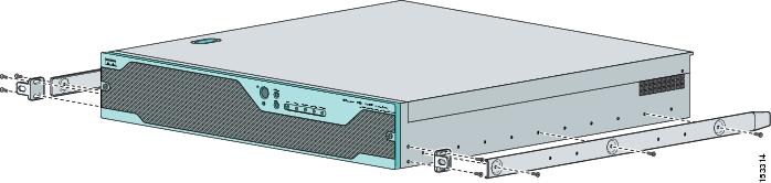
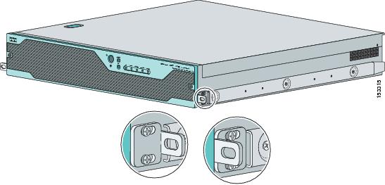
Step 2 ![]() Attach the front-tab mounting bracket to the chassis with two 8-32x1/4' SEMS screws. You can flip the bracket to push the system forward in the rack.
Attach the front-tab mounting bracket to the chassis with two 8-32x1/4' SEMS screws. You can flip the bracket to push the system forward in the rack.
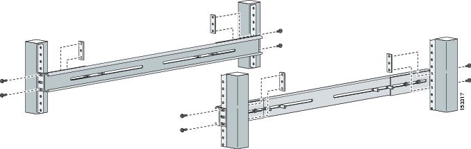
Step 3 ![]() Using the four inner studs, install the mounting brackets to the outer rail with four 8-32 KEPS nuts. Insert four thread covers over the four outer studs on each side.
Using the four inner studs, install the mounting brackets to the outer rail with four 8-32 KEPS nuts. Insert four thread covers over the four outer studs on each side.
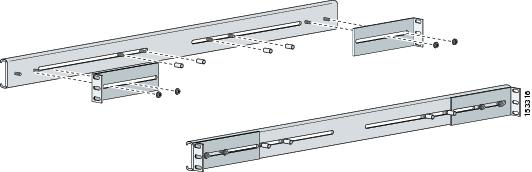
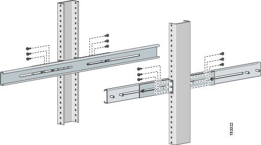
Step 4 ![]() Install the two outer rail subassemblies in the rack using eight 10-32x1/2" SEMS screws. You can use four bar nuts if necessary.
Install the two outer rail subassemblies in the rack using eight 10-32x1/2" SEMS screws. You can use four bar nuts if necessary.
Note ![]() Adjust the mounting brackets based on rack depth.
Adjust the mounting brackets based on rack depth.
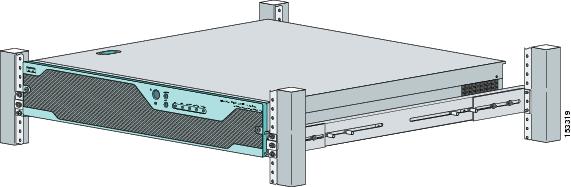
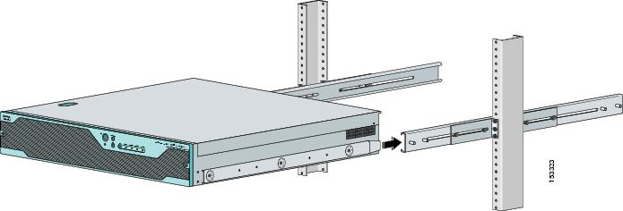
Step 5 ![]() Slide IPS-4260 into the rack making sure the inner rail is aligned with the outer rail.
Slide IPS-4260 into the rack making sure the inner rail is aligned with the outer rail.
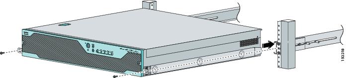
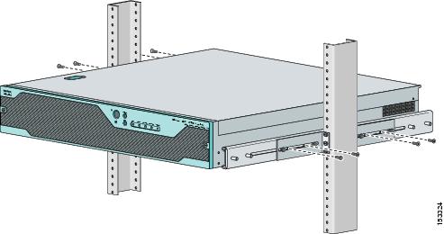
Step 6 ![]() Install two 10-32x1/2" SEMS screws to hold the front-tab mounting bracket to the rail.
Install two 10-32x1/2" SEMS screws to hold the front-tab mounting bracket to the rail.
Installing IPS-4260 in a 2-Post Rack
To rack mount IPS-4260 in a 2-post rack, follow these steps:
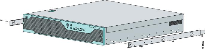
Step 1 ![]() Attach the inner rail to each side of the chassis with three 8-32x1/4" SEMS screws.
Attach the inner rail to each side of the chassis with three 8-32x1/4" SEMS screws.
Step 2 ![]() Using the four inner studs, install the mounting brackets to the outer rail with four 8-32 KEPS nuts. Insert four thread covers over the four outer studs on each side.
Using the four inner studs, install the mounting brackets to the outer rail with four 8-32 KEPS nuts. Insert four thread covers over the four outer studs on each side.
Step 3 ![]() Install the two outer rail subassemblies in the rack using twelve 10-32x1/2" SEMS screws or whatever rack hardware is necessary.
Install the two outer rail subassemblies in the rack using twelve 10-32x1/2" SEMS screws or whatever rack hardware is necessary.
Note ![]() Adjust the mounting brackets based on the rack-channel depth.
Adjust the mounting brackets based on the rack-channel depth.
Step 4 ![]() Slide IPS-4260 into the rack making sure the inner rail is aligned with the outer rail.
Slide IPS-4260 into the rack making sure the inner rail is aligned with the outer rail.
Step 5 ![]() Install four 8-32x7/16" SEMS screws through the clearance slots in the side of each outer rail assembly into the inner rail.
Install four 8-32x7/16" SEMS screws through the clearance slots in the side of each outer rail assembly into the inner rail.
Installing IPS-4260
|
Warning |
To install IPS-4260 on the network, follow these steps:
Step 1 ![]() Position IPS-4260 on the network.
Position IPS-4260 on the network.
Step 2 ![]() Attach the grounding lugs to the back of IPS-4260.
Attach the grounding lugs to the back of IPS-4260.
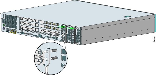
Note ![]() Use 8-32 locknuts to connect a copper standard barrel grounding lug to the holes. The appliance requires a lug where the distance between the center of each hole is 0.56 inches. The ground lug must be NRTL listed or recognized. In addition, the copper conductor (wires) must be used and the copper conductor must comply with the NEC code for ampacity. A lug is not supplied with the appliance.
Use 8-32 locknuts to connect a copper standard barrel grounding lug to the holes. The appliance requires a lug where the distance between the center of each hole is 0.56 inches. The ground lug must be NRTL listed or recognized. In addition, the copper conductor (wires) must be used and the copper conductor must comply with the NEC code for ampacity. A lug is not supplied with the appliance.
Step 3 ![]() Place IPS-4260 in a rack, if you are rack mounting it.
Place IPS-4260 in a rack, if you are rack mounting it.
For the procedure, see Rack Mounting.
Step 4 ![]() Attach the power cord to IPS-4260 and plug it in to a power source (a UPS is recommended).
Attach the power cord to IPS-4260 and plug it in to a power source (a UPS is recommended).
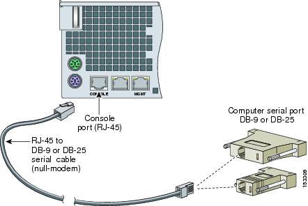
Step 5 ![]() Connect the cable as shown in Step 6 so that you have either a DB-9 or DB-25 connector on one end as required by the serial port for your computer, and the other end is the RJ-45 connector.
Connect the cable as shown in Step 6 so that you have either a DB-9 or DB-25 connector on one end as required by the serial port for your computer, and the other end is the RJ-45 connector.
Note ![]() Use the console port to connect to a computer to enter configuration commands. Locate the serial cable from the accessory kit. The serial cable assembly consists of a 180/rollover cable with RJ-45 connectors (DB-9 connector adapter PN 74-0495-01 and DB-25 connector adapter PN 29-0810-01).
Use the console port to connect to a computer to enter configuration commands. Locate the serial cable from the accessory kit. The serial cable assembly consists of a 180/rollover cable with RJ-45 connectors (DB-9 connector adapter PN 74-0495-01 and DB-25 connector adapter PN 29-0810-01).
Note ![]() You can use a 180/rollover or straight-through patch cable to connect the appliance to a port on a terminal server with RJ-45 or hydra cable assembly connections. Connect the appropriate cable from the console port on the appliance to a port on the terminal server. For the instructions for setting up a terminal server, see Setting Up a Terminal Server.
You can use a 180/rollover or straight-through patch cable to connect the appliance to a port on a terminal server with RJ-45 or hydra cable assembly connections. Connect the appropriate cable from the console port on the appliance to a port on the terminal server. For the instructions for setting up a terminal server, see Setting Up a Terminal Server.
Step 6 ![]() Connect the RJ-45 connector to the console port and connect the other end to the DB-9 or DB-25 connector on your computer.
Connect the RJ-45 connector to the console port and connect the other end to the DB-9 or DB-25 connector on your computer.
Step 7 ![]() Attach the network cables.
Attach the network cables.
IPS-4260 has the following interfaces:
•![]() GigabitEthernet0/1 (GE 0/1) is the sensing port.
GigabitEthernet0/1 (GE 0/1) is the sensing port.
•![]() Management0/0 (MGMT) is the command and control port.
Management0/0 (MGMT) is the command and control port.
•![]() GigabitEthernet2/0 through GigabitEthernet2/3 and GigabitEthernet3/0 through 3/3 are the additional expansion port slots.
GigabitEthernet2/0 through GigabitEthernet2/3 and GigabitEthernet3/0 through 3/3 are the additional expansion port slots.
Step 8 ![]() Power on IPS-4260.
Power on IPS-4260.
Step 9 ![]() Initialize IPS-4260.
Initialize IPS-4260.
For the procedure, see Initializing the Sensor.
Step 10 ![]() Upgrade IPS-4260 with the most recent Cisco IPS software.
Upgrade IPS-4260 with the most recent Cisco IPS software.
For the procedure, see Obtaining Cisco IPS Software.
You are now ready to configure intrusion prevention on IPS-4260.
For More Information
•![]() For the procedure for using HTTPS to log in to IDM, refer to Logging In to IDM.
For the procedure for using HTTPS to log in to IDM, refer to Logging In to IDM.
•![]() For the procedures for configuring intrusion prevention on your sensor, refer to the following documents:
For the procedures for configuring intrusion prevention on your sensor, refer to the following documents:
–![]() Installing and Using Cisco Intrusion Prevention System Device Manager 5.1
Installing and Using Cisco Intrusion Prevention System Device Manager 5.1
–![]() Configuring the Cisco Intrusion Prevention System Sensor Using the Command Line Interface 5.1
Configuring the Cisco Intrusion Prevention System Sensor Using the Command Line Interface 5.1
Removing and Replacing the Chassis Cover
|
Warning |
Note ![]() Removing the appliance chassis cover does not affect your Cisco warranty. Upgrading IPS-4260 does not require any special tools and does not create any radio frequency leaks.
Removing the appliance chassis cover does not affect your Cisco warranty. Upgrading IPS-4260 does not require any special tools and does not create any radio frequency leaks.
To remove and replace the chassis cover, follow these steps:
Step 1 ![]() Log in to the CLI.
Log in to the CLI.
Step 2 ![]() Prepare IPS-4260 to be powered off:
Prepare IPS-4260 to be powered off:
sensor# reset powerdown
Wait for the power down message before continuing with Step 3.
Note ![]() You can also power down IPS-4260 using IDM. For the procedure, refer to Resetting the Appliance.
You can also power down IPS-4260 using IDM. For the procedure, refer to Resetting the Appliance.
Step 3 ![]() Power off IPS-4260.
Power off IPS-4260.
Step 4 ![]() Remove the power cord and other cables from IPS-4260.
Remove the power cord and other cables from IPS-4260.
Step 5 ![]() If rack-mounted, remove IPS-4260 from the rack.
If rack-mounted, remove IPS-4260 from the rack.
For the procedure, see Rack Mounting.
Step 6 ![]() Place IPS-4260 in an ESD-controlled environment.
Place IPS-4260 in an ESD-controlled environment.
For more information, see Working in an ESD Environment.
Step 7 ![]() Press the blue button on the top of the chassis cover and slide the chassis cover back.
Press the blue button on the top of the chassis cover and slide the chassis cover back.
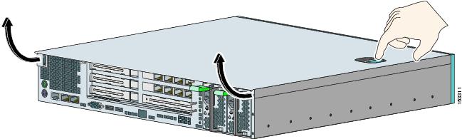
Step 8 ![]() To replace the chassis cover, position it at the back of the chassis and slide it on until it snaps into place.
To replace the chassis cover, position it at the back of the chassis and slide it on until it snaps into place.
Step 9 ![]() Reattach the power cord and other cables to IPS-4260.
Reattach the power cord and other cables to IPS-4260.
For the procedure, see Installing IPS-4260.
Step 10 ![]() Reinstall IPS-4260 on a rack, desktop, or table.
Reinstall IPS-4260 on a rack, desktop, or table.
If you are reinstalling in a rack, see Rack Mounting.
Step 11 ![]() Power on IPS-4260.
Power on IPS-4260.
Installing and Removing PCI Cards
IPS-4260 has 6 expansion card slots, three full-height and three half-height slots. You can install the optional network interface cards in the two top full-height slots, slots 2 and 3. IPS-4260 supports up to two network interface cards. For an illustration of the expansion card slots, see Figure 5-5. For an illustration of the supported PCI cards, see Supported PCI Cards.
Note ![]() We recommend that you install the 4GE bypass interface card in slot 2 if you are installing only one 4GE bypass card. This improves accessibility to the RJ45 cable connectors.
We recommend that you install the 4GE bypass interface card in slot 2 if you are installing only one 4GE bypass card. This improves accessibility to the RJ45 cable connectors.
To install and remove PCI cards, follow these steps:
Step 1 ![]() Log in to the CLI.
Log in to the CLI.
Step 2 ![]() Prepare IPS-4260 to be powered off:
Prepare IPS-4260 to be powered off:
sensor# reset powerdown
Wait for the power down message before continuing with Step 3.
Note ![]() You can also power down IPS-4260 using IDM. For the procedure, refer to Resetting the Appliance.
You can also power down IPS-4260 using IDM. For the procedure, refer to Resetting the Appliance.
Step 3 ![]() Power off IPS-4260.
Power off IPS-4260.
Step 4 ![]() Remove the power cord and other cables from IPS-4260.
Remove the power cord and other cables from IPS-4260.
Step 5 ![]() If rack-mounted, remove IPS-4260 from the rack.
If rack-mounted, remove IPS-4260 from the rack.
For the procedure, see Rack Mounting.
Step 6 ![]() Place IPS-4260 in an ESD-controlled environment.
Place IPS-4260 in an ESD-controlled environment.
For more information, see Working in an ESD Environment.
Step 7 ![]() Remove the chassis cover.
Remove the chassis cover.
For the procedure, see Removing and Replacing the Chassis Cover.
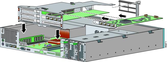
Step 8 ![]() Remove the card carrier by pulling up on the two blue release tabs. Use equal pressure and lift the card carrier out of the chassis.
Remove the card carrier by pulling up on the two blue release tabs. Use equal pressure and lift the card carrier out of the chassis.

Step 9 ![]() With a screw driver, remove the screw from the desired slot cover.
With a screw driver, remove the screw from the desired slot cover.
Step 10 ![]() Remove the slot cover by pressing on it from inside the chassis.
Remove the slot cover by pressing on it from inside the chassis.
If the card is full length, use a screw driver to remove the blue thumb screw from the card support at the back of the card carrier.
Step 11 ![]() Carefully align the PCI card with the PCI-Express connector and alignment grooves for the appropriate slot. Apply firm even pressure until the card is fully seated in the connector.
Carefully align the PCI card with the PCI-Express connector and alignment grooves for the appropriate slot. Apply firm even pressure until the card is fully seated in the connector.
Step 12 ![]() Reinstall the slot cover screw to hold the card to the carrier. If necessary, reinstall the card support at the back of the card carrier.
Reinstall the slot cover screw to hold the card to the carrier. If necessary, reinstall the card support at the back of the card carrier.
Step 13 ![]() Replace the card carrier in the chassis.
Replace the card carrier in the chassis.
Step 14 ![]() Replace the chassis cover.
Replace the chassis cover.
Installing and Removing the Power Supply
IPS-4260 ships with one power supply, but you can order it with two power supplies so that you have a redundant power supply.
To install and remove power supplies, follow these steps:
Step 1 ![]() Log in to the CLI.
Log in to the CLI.
Step 2 ![]() Prepare IPS-4260 to be powered off:
Prepare IPS-4260 to be powered off:
sensor# reset powerdown
Wait for the power down message before continuing with Step 3.
Note ![]() You can also power down IPS-4260 using IDM. For the procedure, refer to Resetting the Appliance.
You can also power down IPS-4260 using IDM. For the procedure, refer to Resetting the Appliance.
Step 3 ![]() Power off IPS-4260.
Power off IPS-4260.
Step 4 ![]() Remove the power cord and other cables from IPS-4260.
Remove the power cord and other cables from IPS-4260.
Note ![]() Power supplies are hot-swappable. You can replace a power supply while IPS-4260 is running, if you are replacing a redundant power supply.
Power supplies are hot-swappable. You can replace a power supply while IPS-4260 is running, if you are replacing a redundant power supply.
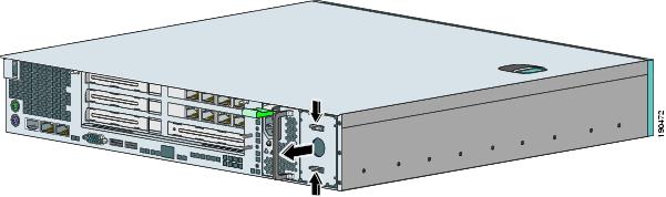
Step 5 ![]() Squeeze the tabs to remove the filler plate.
Squeeze the tabs to remove the filler plate.
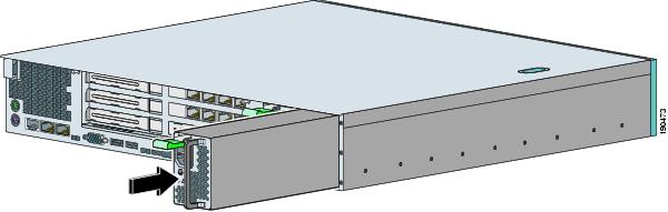
Step 6 ![]() Install the power supply.
Install the power supply.
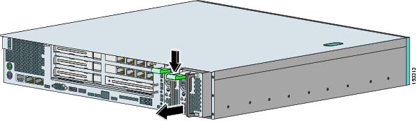
Step 7 ![]() To remove the power supply, push down the green tab and pull out the power supply.
To remove the power supply, push down the green tab and pull out the power supply.
Step 8 ![]() After installing or removing the power supply, replace the power cord and other cables.
After installing or removing the power supply, replace the power cord and other cables.
Step 9 ![]() Power on IPS-4260.
Power on IPS-4260.
 Feedback