- About this Guide
-
- Information About Cisco Unified Communications Features
- Using the Cisco Unified Communication Wizard
- Configuring the Cisco Phone Proxy
- Configuring the TLS Proxy for Encrypted Voice Inspection
- Configuring Cisco Mobility Advantage
- Configuring Cisco Unified Presence
- Configuring Cisco Unified Communications Intercompany Media Engine
- Index
CLI Book 2: Cisco ASA Series Firewall CLI Configuration Guide, 9.1
Bias-Free Language
The documentation set for this product strives to use bias-free language. For the purposes of this documentation set, bias-free is defined as language that does not imply discrimination based on age, disability, gender, racial identity, ethnic identity, sexual orientation, socioeconomic status, and intersectionality. Exceptions may be present in the documentation due to language that is hardcoded in the user interfaces of the product software, language used based on RFP documentation, or language that is used by a referenced third-party product. Learn more about how Cisco is using Inclusive Language.
- Updated:
- August 14, 2014
Chapter: Configuring the ASA IPS Module
- Information About the ASA IPS Module
- Licensing Requirements for the ASA IPS module
- Guidelines and Limitations
- Default Settings
- Configuring the ASA IPS module
- Task Flow for the ASA IPS Module
- Connecting the ASA IPS Management Interface
- Sessioning to the Module from the ASA
- (ASA 5512-X through ASA 5555-X) Booting the Software Module
- Configuring Basic IPS Module Network Settings
- Configuring the Security Policy on the ASA IPS Module
- Assigning Virtual Sensors to a Security Context (ASA 5510 and Higher)
- Diverting Traffic to the ASA IPS module
- Managing the ASA IPS module
- Monitoring the ASA IPS module
- Configuration Examples for the ASA IPS module
- Feature History for the ASA IPS module
Configuring the ASA IPS Module
This chapter describes how to configure the ASA IPS module. The ASA IPS module might be a hardware module or a software module, depending on your ASA model. For a list of supported ASA IPS modules per ASA model, see the Cisco ASA Compatibility Matrix :
http://www.cisco.com/en/US/docs/security/asa/compatibility/asamatrx.html
This chapter includes the following sections:
- Information About the ASA IPS Module
- Licensing Requirements for the ASA IPS module
- Guidelines and Limitations
- Default Settings
- Configuring the ASA IPS module
- Managing the ASA IPS module
- Monitoring the ASA IPS module
- Configuration Examples for the ASA IPS module
- Feature History for the ASA IPS module
Information About the ASA IPS Module
The ASA IPS module runs advanced IPS software that provides proactive, full-featured intrusion prevention services to stop malicious traffic, including worms and network viruses, before they can affect your network. This section includes the following topics:
- How the ASA IPS Module Works with the ASA
- Operating Modes
- Using Virtual Sensors (ASA 5510 and Higher)
- Information About Management Access
How the ASA IPS Module Works with the ASA
The ASA IPS module runs a separate application from the ASA. The ASA IPS module might include an external management interface so you can connect to the ASA IPS module directly; if it does not have a management interface, you can connect to the ASA IPS module through the ASA interface. The ASA IPS SSP on the ASA 5585-X includes data interfaces; these interfaces provide additional port-density for the ASA. However, the overall through-put of the ASA is not increased.
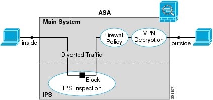
Traffic goes through the firewall checks before being forwarded to the ASA IPS module. When you identify traffic for IPS inspection on the ASA, traffic flows through the ASA and the ASA IPS module as follows. Note : This example is for “inline mode.” See the “Operating Modes” section for information about “promiscuous mode,” where the ASA only sends a copy of the traffic to the ASA IPS module.
2. Incoming VPN traffic is decrypted.
3. Firewall policies are applied.
4. Traffic is sent to the ASA IPS module.
5. The ASA IPS module applies its security policy to the traffic, and takes appropriate actions.
6. Valid traffic is sent back to the ASA; the ASA IPS module might block some traffic according to its security policy, and that traffic is not passed on.
7. Outgoing VPN traffic is encrypted.
Figure 31-1 shows the traffic flow when running the ASA IPS module in inline mode. In this example, the ASA IPS module automatically blocks traffic that it identified as an attack. All other traffic is forwarded through the ASA.
Figure 31-1 ASA IPS module Traffic Flow in the ASA: Inline Mode
Operating Modes
You can send traffic to the ASA IPS module using one of the following modes:
- Inline mode—This mode places the ASA IPS module directly in the traffic flow (see Figure 31-1). No traffic that you identified for IPS inspection can continue through the ASA without first passing through, and being inspected by, the ASA IPS module. This mode is the most secure because every packet that you identify for inspection is analyzed before being allowed through. Also, the ASA IPS module can implement a blocking policy on a packet-by-packet basis. This mode, however, can affect throughput.
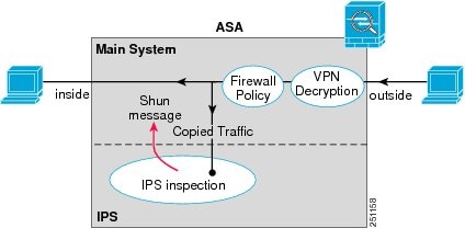
- Promiscuous mode—This mode sends a duplicate stream of traffic to the ASA IPS module. This mode is less secure, but has little impact on traffic throughput. Unlike inline mode, in promiscuous mode the ASA IPS module can only block traffic by instructing the ASA to shun the traffic or by resetting a connection on the ASA. Also, while the ASA IPS module is analyzing the traffic, a small amount of traffic might pass through the ASA before the ASA IPS module can shun it. Figure 31-2 shows the ASA IPS module in promiscuous mode. In this example, the ASA IPS module sends a shun message to the ASA for traffic it identified as a threat.
Figure 31-2 ASA IPS module Traffic Flow in the ASA: Promiscuous Mode
Using Virtual Sensors (ASA 5510 and Higher)
The ASA IPS module running IPS software Version 6.0 and later can run multiple virtual sensors, which means you can configure multiple security policies on the ASA IPS module. You can assign each ASA security context or single mode ASA to one or more virtual sensors, or you can assign multiple security contexts to the same virtual sensor. See the IPS documentation for more information about virtual sensors, including the maximum number of sensors supported.
Figure 31-3 shows one security context paired with one virtual sensor (in inline mode), while two security contexts share the same virtual sensor.
Figure 31-3 Security Contexts and Virtual Sensors
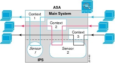
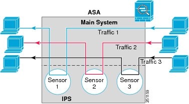
Figure 31-4 shows a single mode ASA paired with multiple virtual sensors (in inline mode); each defined traffic flow goes to a different sensor.
Figure 31-4 Single Mode ASA with Multiple Virtual Sensors
Information About Management Access
You can manage the IPS application using the following methods:
- Sessioning to the module from the ASA—If you have CLI access to the ASA, then you can session to the module and access the module CLI. See the “Sessioning to the Module from the ASA” section.
- Connecting to the IPS management interface using ASDM or SSH—After you launch ASDM from the ASA, your management station connects to the module management interface to configure the IPS application. For SSH, you can access the module CLI directly on the module management interface. (Telnet access requires additional configuration in the module application). The module management interface can also be used for sending syslog messages or allowing updates for the module application, such as signature database updates.
See the following information about the management interface:
– ASA 5510, ASA 5520, ASA 5540, ASA 5580, ASA 5585-X—The IPS management interface is a separate external Gigabit Ethernet interface.
– ASA 5512-X, ASA 5515-X, ASA 5525-X, ASA 5545-X, ASA 5555-X—These models run the ASA IPS module as a software module. The IPS management interface shares the Management 0/0 interface with the ASA. Separate MAC addresses and IP addresses are supported for the ASA and ASA IPS module. You must perform configuration of the IPS IP address within the IPS operating system (using the CLI or ASDM). However, physical characteristics (such as enabling the interface) are configured on the ASA. You can remove the ASA interface configuration (specifically the interface name) to dedicate this interface as an IPS-only interface. This interface is management-only.
– ASA 5505—You can use an ASA VLAN to allow access to an internal management IP address over the backplane.
Licensing Requirements for the ASA IPS module
The following table shows the licensing requirements for this feature:
Guidelines and Limitations
This section includes the guidelines and limitations for this feature.
The ASA 5505 does not support multiple context mode, so multiple context features, such as virtual sensors, are not supported on the AIP SSC.
Supported in routed and transparent firewall mode.
http://www.cisco.com/en/US/docs/security/asa/compatibility/asamatrx.html
- The ASA 5505 does not support multiple context mode, so multiple context features, such as virtual sensors, are not supported on the AIP SSC.
- The ASA IPS module for the ASA 5510 and higher supports higher performance requirements, while the ASA IPS module for the ASA 5505 is designed for a small office installation. The following features are not supported for the ASA 5505:
– Unretirement of default retired signatures
– ASA 5512-X through ASA 5555-X—See http://www.cisco.com/en/US/prod/collateral/vpndevc/ps6032/ps6094/ps6120/qa_c67-700608.html
– ASA 5585-X—See http://www.cisco.com/en/US/prod/collateral/vpndevc/ps6032/ps6094/ps6120/qa_c67-617018.html
– ASA 5505 through ASA 5540—See http://www.cisco.com/en/US/prod/collateral/vpndevc/ps6032/ps6094/ps6120/product_data_sheet0900aecd802930c5.html
Default Settings
Table 31-1 lists the default settings for the ASA IPS module.

Note The default management IP address on the ASA is 192.168.1.1/24.
Configuring the ASA IPS module
This section describes how to configure the ASA IPS module and includes the following topics:
- Task Flow for the ASA IPS Module
- Connecting the ASA IPS Management Interface
- Sessioning to the Module from the ASA
- Configuring Basic IPS Module Network Settings
- (ASA 5512-X through ASA 5555-X) Booting the Software Module
- Configuring the Security Policy on the ASA IPS Module
- Assigning Virtual Sensors to a Security Context (ASA 5510 and Higher)
- Diverting Traffic to the ASA IPS module
Task Flow for the ASA IPS Module
Configuring the ASA IPS module is a process that includes configuration of the IPS security policy on the ASA IPS module and then configuration of the ASA to send traffic to the ASA IPS module. To configure the ASA IPS module, perform the following steps:
Step 1 Cable the ASA IPS management interface. See the “Connecting the ASA IPS Management Interface” section.
Step 2 Session to the module. Access the IPS CLI over the backplane.See the “Sessioning to the Module from the ASA” section.
Step 3 (ASA 5512-X through ASA 5555-X; may be required) Install the software module. See the “(ASA 5512-X through ASA 5555-X) Booting the Software Module” section.
Step 4 Depending on your ASA model:
- (ASA 5510 and higher) Configure basic network settings for the IPS module. See the “(ASA 5510 and Higher) Configuring Basic Network Settings” section.
- (ASA 5505) Configure the management VLAN and IP address for the IPS module. See the “(ASA 5505) Configuring Basic Network Settings” section.
Step 5 On the module, configure the inspection and protection policy, which determines how to inspect traffic and what to do when an intrusion is detected. See the “Configuring the Security Policy on the ASA IPS Module” section.
Step 6 (ASA 5510 and higher, optional) On the ASA in multiple context mode, specify which IPS virtual sensors are available for each context (if you configured virtual sensors). See the “Assigning Virtual Sensors to a Security Context (ASA 5510 and Higher)” section.
Step 7 On the ASA, identify traffic to divert to the ASA IPS module. See the “Diverting Traffic to the ASA IPS module” section.
Connecting the ASA IPS Management Interface
In addition to providing management access to the IPS module, the IPS management interface needs access to an HTTP proxy server or a DNS server and the Internet so it can download global correlation, signature updates, and license requests. This section describes recommended network configurations. Your network may differ.
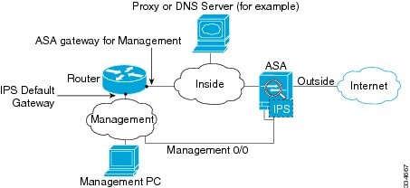
ASA 5510, ASA 5520, ASA 5540, ASA 5580, ASA 5585-X (Hardware Module)
The IPS module includes a separate management interface from the ASA.
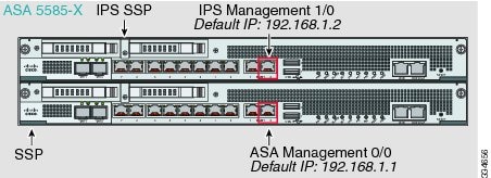
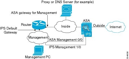
If you have an inside router, you can route between the management network, which can include both the ASA Management 0/0 and IPS Management 1/0 interfaces, and the ASA inside network. Be sure to also add a route on the ASA to reach the Management network through the inside router.
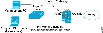
If you do not have an inside router
If you have only one inside network, then you cannot also have a separate management network, which would require an inside router to route between the networks. In this case, you can manage the ASA from the inside interface instead of the Management 0/0 interface. Because the IPS module is a separate device from the ASA, you can configure the IPS Management 1/0 address to be on the same network as the inside interface.
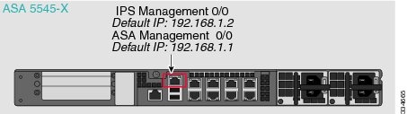
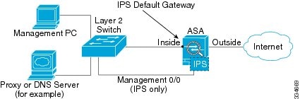
ASA 5512-X through ASA 5555-X (Software Module)
These models run the IPS module as a software module, and the IPS management interface shares the Management 0/0 interface with the ASA.
If you have an inside router, you can route between the Management 0/0 network, which includes both the ASA and IPS management IP addresses, and the inside network. Be sure to also add a route on the ASA to reach the Management network through the inside router.
If you do not have an inside router
If you have only one inside network, then you cannot also have a separate management network. In this case, you can manage the ASA from the inside interface instead of the Management 0/0 interface. If you remove the ASA-configured name from the Management 0/0 interface, you can still configure the IPS IP address for that interface. Because the IPS module is essentially a separate device from the ASA, you can configure the IPS management address to be on the same network as the inside interface.
Note You must remove the ASA-configured name for Management 0/0; if it is configured on the ASA, then the IPS address must be on the same network as the ASA, and that excludes any networks already configured on other ASA interfaces. If the name is not configured, then the IPS address can be on any network, for example, the ASA inside network.
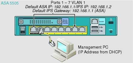
ASA 5505
The ASA 5505 does not have a dedicated management interface. You must use an ASA VLAN to access an internal management IP address over the backplane. Connect the management PC to one of the following ports: Ethernet 0/1 through 0/7, which are assigned to VLAN 1.
What to Do Next
- (ASA 5510 and higher) Configure basic network settings. See the “(ASA 5510 and Higher) Configuring Basic Network Settings” section.
- (ASA 5505) Configure management interface settings. See the “(ASA 5505) Configuring Basic Network Settings” section.
Sessioning to the Module from the ASA
To access the IPS module CLI from the ASA, you can session from the ASA. For software modules, you can either session to the module (using Telnet) or create a virtual console session. A console session might be useful if the control plane is down and you cannot establish a Telnet session.
Detailed Steps
(ASA 5512-X through ASA 5555-X) Booting the Software Module
Your ASA typically ships with IPS module software present on Disk0. If the module is not running, or if you are adding the IPS module to an existing ASA, you must boot the module software. If you are unsure if the module is running, you will not be able to session it.
Detailed Steps
Step 1 Do one of the following:
For example, look for a filename like IPS-SSP_5512-K9-sys-1.1-a-7.1-4-E4.aip. Note the filename; you will need this filename later in the procedure.
http://www.cisco.com/cisco/software/navigator.html?mdfid=282164240
For other download server types, see “Managing Software and Configurations,” in the general operations configuration guide.
Note the filename; you will need this filename later in the procedure.
Step 2 To set the IPS module software location in disk0, enter the following command:
For example, using the filename in the example in Step 1, enter:
Step 3 To install and load the IPS module software, enter the following command:
Step 4 To check the progress of the image transfer and module restart process, enter the following command:
The Status field in the output indicates the operational status of the module. A module operating normally shows a status of “Up.” While the ASA transfers an application image to the module, the Status field in the output reads “Recover.” When the ASA completes the image transfer and restarts the module, the newly transferred image is running.
(ASA 5510 and Higher) Configuring Basic Network Settings
Session to the module from the ASA and configure basic settings using the setup command.
Note (ASA 5512-X through ASA 5555-X) If you cannot session to the module, then the IPS module is not running. See the “(ASA 5512-X through ASA 5555-X) Booting the Software Module” section, and then repeat this procedure after you install the module.
Detailed Steps
Session to the IPS module according to the “Sessioning to the Module from the ASA” section. |
||
Runs the setup utility for initial configuration of the ASA IPS module. You are prompted for basic settings. For the default gateway, specify the IP address of the upstream router. See the “Connecting the ASA IPS Management Interface” section to understand the requirements for your network. The default setting of the ASA management IP address will not work. |
(ASA 5505) Configuring Basic Network Settings
An ASA IPS module on the ASA 5505 does not have any external interfaces. You can configure a VLAN to allow access to an internal IPS management IP address over the backplane. By default, VLAN 1 is enabled for IPS management. You can only assign one VLAN as the management VLAN. This section describes how to change the management VLAN and IP address if you do not want to use the default, and how to set other required network parameters.
Note Perform this configuration on the ASA 5505, not on the ASA IPS module.
Prerequisites
When you change the IPS VLAN and management address from the default, be sure to also configure the matching ASA VLAN and switch port(s) according to the procedures listed in “Starting Interface Configuration (ASA 5505),” in the general operations configuration guide. You must define and configure the VLAN for the ASA so the IPS management interface is accessible on the network.
Restrictions
Do not configure NAT for the management address if you intend to access it using ASDM. For initial setup with ASDM, you need to access the real address. After initial setup (where you set the password on the ASA IPS module), you can configure NAT and supply ASDM with the translated address for accessing the ASA IPS module.
Detailed Steps
Examples
The following example configures VLAN 20 as the IPS management VLAN. Only the host at 10.1.1.30 can access the IPS management IP address. VLAN 20 is assigned to switch port Ethernet 0/0. When you connect to ASDM on ASA interface 10.1.1.1, ASDM then accesses the IPS on 10.1.1.2.
Configuring the Security Policy on the ASA IPS Module
This section describes how to configure the ASA IPS module application.
Detailed Steps
Step 1 Access the ASA IPS module CLI using one of the following methods:
- Session from the ASA to the ASA IPS module. See the “Sessioning to the Module from the ASA” section.
- Connect to the IPS management interface using SSH. If you did not change it, the default management IP address is 192.168.1.2. The default username is cisco , and the default password is cisco . See the “Information About Management Access” section for more information about the management interface.
Step 2 Configure the IPS security policy according to the IPS documentation.
To access all documents related to IPS, go to: http://www.cisco.com/en/US/products/hw/vpndevc/ps4077/products_documentation_roadmaps_list.html
Step 3 (ASA 5510 and higher) If you configure virtual sensors, you identify one of the sensors as the default. If the ASA does not specify a virtual sensor name in its configuration, the default sensor is used.
Step 4 When you are done configuring the ASA IPS module, exit the IPS software by entering the following command:
If you sessioned to the ASA IPS module from the ASA, you return to the ASA prompt.
What to Do Next
- For the ASA in multiple context mode, see the “Assigning Virtual Sensors to a Security Context (ASA 5510 and Higher)” section.
- For the ASA in single context mode, see the “Diverting Traffic to the ASA IPS module” section.
Assigning Virtual Sensors to a Security Context (ASA 5510 and Higher)
If the ASA is in multiple context mode, then you can assign one or more IPS virtual sensors to each context. Then, when you configure the context to send traffic to the ASA IPS module, you can specify a sensor that is assigned to the context; you cannot specify a sensor that you did not assign to the context. If you do not assign any sensors to a context, then the default sensor configured on the ASA IPS module is used. You can assign the same sensor to multiple contexts.
Note You do not need to be in multiple context mode to use virtual sensors; you can be in single mode and use different sensors for different traffic flows.
Prerequisites
For more information about configuring contexts, see the “Configuring Multiple Contexts” section in the general operations configuration guide.
Detailed Steps
Identifies the context you want to configure. Enter this command in the system execution space. |
||
Enter this command for each sensor you want to assign to the context. The sensor _name argument is the sensor name configured on the ASA IPS module. To view the sensors that are configured on the ASA IPS module, enter allocate-ips ? . All available sensors are listed. You can also enter the show ips command. In the system execution space, the show ips command lists all available sensors; if you enter it in the context, it shows the sensors you already assigned to the context. If you specify a sensor name that does not yet exist on the ASA IPS module, you get an error, but the allocate-ips command is entered as is. Until you create a sensor of that name on the ASA IPS module, the context assumes the sensor is down. Use the mapped_name argument as an alias for the sensor name that can be used within the context instead of the actual sensor name. If you do not specify a mapped name, the sensor name is used within the context. For security purposes, you might not want the context administrator to know which sensors are being used by the context. Or you might want to genericize the context configuration. For example, if you want all contexts to use sensors called “sensor1” and “sensor2,” then you can map the “highsec” and “lowsec” sensors to sensor1 and sensor2 in context A, but map the “medsec” and “lowsec” sensors to sensor1 and sensor2 in context B. The default keyword sets one sensor per context as the default sensor; if the context configuration does not specify a sensor name, the context uses this default sensor. You can only configure one default sensor per context. If you want to change the default sensor, enter the no allocate-ips sensor_name command to remove the current default sensor before you allocate a new default sensor. If you do not specify a sensor as the default, and the context configuration does not include a sensor name, then traffic uses the default sensor as specified on the ASA IPS module. |
||
Changes to the context so you can configure the IPS security policy as described in “Diverting Traffic to the ASA IPS module” section. |
Examples
The following example assigns sensor1 and sensor2 to context A, and sensor1 and sensor3 to context B. Both contexts map the sensor names to “ips1” and “ips2.” In context A, sensor1 is set as the default sensor, but in context B, no default is set so the default that is configured on the ASA IPS module is used.
What to Do Next
Change to each context to configure the IPS security policy as described in “Diverting Traffic to the ASA IPS module” section.
Diverting Traffic to the ASA IPS module
This section identifies traffic to divert from the ASA to the ASA IPS module.
Prerequisites
In multiple context mode, perform these steps in each context execution space. To change to a context, enter the changeto context context_name command.
Detailed Steps
Creates a class map to identify the traffic for which you want to send to the ASA IPS module. If you want to send multiple traffic classes to the ASA IPS module, you can create multiple class maps for use in the security policy. |
||
Specifies the traffic in the class map. See the “Identifying Traffic (Layer 3/4 Class Maps)” section for more information. |
||
Adds or edits a policy map that sets the actions to take with the class map traffic. |
||
Identifies the class map you created in Step 1. |
||
ips { inline | promiscuous } { fail-close | fail-open } [ sensor { sensor_name | mapped_name }] |
Specifies that the traffic should be sent to the ASA IPS module. The inline and promiscuous keywords control the operating mode of the ASA IPS module. See the “Operating Modes” section for more details. The fail-close keyword sets the ASA to block all traffic if the ASA IPS module is unavailable. The fail-open keyword sets the ASA to allow all traffic through, uninspected, if the ASA IPS module is unavailable. (ASA 5510 and higher) If you use virtual sensors, you can specify a sensor name using the sensor sensor_name argument. To see available sensor names, enter the ips { inline | promiscuous } { fail-close | fail-open } sensor ? command. Available sensors are listed. You can also use the show ips command. If you use multiple context mode on the ASA, you can only specify sensors that you assigned to the context (see the “Assigning Virtual Sensors to a Security Context (ASA 5510 and Higher)” section). Use the mapped_name if configured in the context. If you do not specify a sensor name, then the traffic uses the default sensor. In multiple context mode, you can specify a default sensor for the context. In single mode or if you do not specify a default sensor in multiple mode, the traffic uses the default sensor that is set on the ASA IPS module. If you enter a name that does not yet exist on the ASA IPS module, you get an error, and the command is rejected. |
|
If you created multiple class maps for IPS traffic, you can specify another class for the policy. See the “Feature Matching Within a Service Policy” section for detailed information about how the order of classes matters within a policy map. Traffic cannot match more than one class map for the same action type; so if you want network A to go to sensorA, but want all other traffic to go to sensorB, then you need to enter the class command for network A before you enter the class command for all traffic; otherwise all traffic (including network A) will match the first class command, and will be sent to sensorB. |
||
|
ips { inline | promiscuous } { fail-close | fail-open } [ sensor { sensor_name | mapped_name }] |
Specifies that the second class of traffic should be sent to the ASA IPS module. |
|
service-policy policymap_name {global | interface interface_name } |
Activates the policy map on one or more interfaces. global applies the policy map to all interfaces, and interface applies the policy to one interface. Only one global policy is allowed. You can override the global policy on an interface by applying a service policy to that interface. You can only apply one policy map to each interface. |
Managing the ASA IPS module
This section includes procedures that help you recover or troubleshoot the module and includes the following topics:
- Installing and Booting an Image on the Module
- Shutting Down the Module
- Uninstalling a Software Module Image
- Resetting the Password
- Reloading or Resetting the Module
Installing and Booting an Image on the Module
If the module suffers a failure, and the module application image cannot run, you can reinstall a new image on the module from a TFTP server (for a hardware module), or from the local disk (software module).
Note Do not use the upgrade command within the module software to install the image.
Prerequisites
Note This process can take approximately 15 minutes to complete, depending on your network and the size of the image.
Note Before you download the IPS software to disk0, make sure at least 50% of the flash memory is free. When you install IPS, IPS reserves 50% of the internal flash memory for its file system.
Detailed Steps
Shutting Down the Module
Shutting down the module software prepares the module to be safely powered off without losing configuration data. Note : If you reload the ASA, the module is not automatically shut down, so we recommend shutting down the module before reloading the ASA. To gracefully shut down the module, perform the following steps at the ASA CLI.
Uninstalling a Software Module Image
To uninstall a software module image and associated configuration, perform the following steps.
Detailed Steps
Resetting the Password
You can reset the module password to the default. For the user cisco , the default password is cisco . After resetting the password, you should change it to a unique value using the module application.
Resetting the module password causes the module to reboot. Services are not available while the module is rebooting.
To reset the module password to the default of cisco, perform the following steps.
Reloading or Resetting the Module
To reload or reset the module, enter one of the following commands at the ASA CLI.
Monitoring the ASA IPS module
To check the status of a module, enter one of the following commands:
Configuration Examples for the ASA IPS module
The following example diverts all IP traffic to the ASA IPS module in promiscuous mode, and blocks all IP traffic if the ASA IPS module card fails for any reason:
The following example diverts all IP traffic destined for the 10.1.1.0 network and the 10.2.1.0 network to the AIP SSM in inline mode, and allows all traffic through if the AIP SSM fails for any reason. For the my-ips-class traffic, sensor1 is used; for the my-ips-class2 traffic, sensor2 is used.
Feature History for the ASA IPS module
Table 31-2 lists each feature change and the platform release in which it was implemented.
 Feedback