The Cisco Fourth-Generation T1/E1 Voice and WAN Network Interface Modules (NIM) are inserted into the NIM slot on the router to provide T1, fractional T1, E1, and fractional E1 support for data and voice applications.
Restrictions
- When you configure a media address pool for TDM gateways and CUBE, you must configure the media address pool port range in voice service VoIP configuration mode.
- The NIM-8T1E1-PRI module is only supported on Cisco IOS XE releases 3.10.3, 3.11.2, and 3.12.
Information About Cisco Fourth-Generation T1/E1 Voice and WAN Network Interface Module
The Cisco Fourth-Generation T1/E1 Voice and WAN Network Interface Module requires a PVDM4 to be installed for voice support. The following table lists the Cisco Fourth-Generation T1/E1 Voice and WAN Network Interface Modules.
|
Network Interface Module |
Description |
|---|---|
|
NIM-1CE1T1-PRI |
1-port channelized data module. Supports 24/31 channel groups for T1/E1 per port. |
|
NIM-2CE1T1-PRI |
2-port channelized data module. Supports 24/31 channel groups for T1/E1 per port. |
|
NIM-8CE1T1-PRI |
8-port channelized data module. Supports 24/31 channel groups for T1/E1 per port. |
|
NIM-1MFT-T1/E1 |
1-port clear channel data and voice T1/E1 module. Supports 2 channel groups per port. |
|
NIM-2MFT-T1/E1 |
2-port clear channel data and voice T1/E1 module. Supports 2 channel groups per port. |
|
NIM-4MFT-T1/E1 |
4-port clear channel data and voice T1/E1 module. Supports 2 channel groups per port. |
|
NIM-8MFT-T1/E1 |
8-port clear channel data and voice T1/E1 module. Supports 2 channel groups per port. |
Platform and Hardware Support
The Cisco Fourth-Generation T1/E1 Voice and WAN Network Interface Module supports the following platforms:
-
Cisco 4000 Series Integrated Services Router
-
Cisco 5400 Series Enterprise Network Compute System
The Cisco Fourth-Generation T1/E1 Voice and WAN Network Interface Module supports only the Cisco Packet Voice Digital Signal Processor Module version 4 (PVDM4).
 Note |
Cisco 5400 Series Enterprise Network Compute System (ENCS) supports these modules starting from Release NFVIS 3.9.1 and ISRv 16.9.1. Cisco 5400 Series ENCS platforms do not support the network-clock command. Either an external line or an internal oscillator supplies the clock to the NIM module. |
Note |
The Cisco 5400 Series Enterprise Network Compute System (ENCS) does not support voice functionality for the T1/E1 voice and WAN Network Interface Module. |
Features Supported on Cisco Fourth-Generation T1/E1 Voice and WAN Network Interface Module
- Data and voice support on T1/E1
- TCL and IVR application
- Support for DSP Media Services on the motherboard
- Support for Cisco Unified Border Element
- Support for Cisco Survivable Remote Site Telephony
H.323
H.323 is an umbrella recommendation from the International Telecommunication Union (ITU) that defines the protocols to provide voice and video communication sessions on a packet network. The H.323 standard addresses call signaling and control, multimedia transport and control, and bandwidth control for point-to-point and multipoint sessions. For more information about H.323, see the H.323 Configuration Guide. For router configuration information, see the “Configuring H.323 Gateways” chapter of H.323 Configuration Guide.
Session Initiation Protocol
Session Initiation Protocol (SIP) is a peer-to-peer, multimedia signaling protocol developed by the IETF (IETF RFC 3261). Session Initiation Protocol is ASCII-based. It resembles HTTP, and it reuses existing IP protocols (such as DNS and SDP) to provide media setup and teardown. For more information, see the SIP Configuration Guide. For router configuration information under SIP, see the “Basic SIP Configuration” chapter of the SIP Configuration Guide.
Voice gateways provide voice security through SIP enhancements within the Cisco IOS Firewall. SIP inspect functionality (SIP packet inspection and detection of pin-hole openings) is provided, as well as protocol conformance and application security. The user is given more granular control on the policies and security checks applied to SIP traffic, and the capability to filter unwanted messages. For more information, see “Cisco IOS Firewall: SIP Enhancements: ALG and AIC.”
Encapsulation
To configure encapsulation on the interface:
- enable
- configure terminal
- interface serial slot/subslot/port:channel-group
- encapsulation {hdlc | frame-relay | ppp}
DSP Resources
The PVDM4 is a hardware module that provides DSP resources that enable Cisco Integrated Services Routers to provide voice, video, conference, transcoding, and other collaboration services.
DSP-farm Profiles
A DSP-farm is the collection of available DSP resources. DSP-farm profiles are created to allocate DSP-farm resources. A DSP-farm profile allows you to group DSP resources based on the service type. Under a DSP farm profile, you select the service type (conference, transcode, or Media Termination Point [MTP]), associate an application, and specify service-specific parameters such as codecs and maximum number of sessions. Applications associated with the profile, such as SCCP, can use the resources allocated under the profile. You can configure multiple profiles for the same service, each of which can register with one Cisco Unified Communications Manager group. The profile ID and service type uniquely identify a profile, allowing the profile to uniquely map to a Cisco Unified Communications Manager group that contains a single pool of Cisco Unified Communications Manager servers.
Conferencing
Voice conferencing involves adding several parties to a phone conversation. In a traditional circuit-switched voice network, all voice traffic passes through a central device such as a PBX. Conference services are provided within this central device. In contrast, IP phones normally send voice signals directly between phones, without the need to go through a central device. Conference services, however, require a network-based conference bridge.
In an IP telephony network using Cisco Unified Communications Manager, the Conferencing and Transcoding for Voice Gateway Routers feature provides the conference-bridging service. Cisco Unified Communications Manager uses a DSP farm to mix voice streams from multiple participants into a single conference-call stream. The mixed stream is played to all conference attendees, minus the voice of the receiving attendee.
The Ad Hoc and Meet-Me conferencing features are supported (a conference can be either of these types):
- Ad Hoc—The person controlling the conference presses the telephone conference button and adds callers one by one.
- Meet-Me—Participants call in to a central number and are joined in a single conference.
- Participants whose end devices use different codec types are joined in a single conference; no additional transcoding resource is needed.
Network Synchronization for the Cisco 4000 Series ISRs
For Cisco 4000 Series ISRs, the clocking mechanism on T1/E1 interfaces is architecturally different from the previous generations of ISRs. You must always have network-clock synchronization automatic global command configured which may not be default based on IOS-XE version. This ensures that the clocking is started on the modules.
There is no default clock source on Cisco 4000 Series ISR backplane. In Cisco 4000 Series ISRs, the NIM module can be its own clock domain if no network-clock synchronization participate command is configured for that NIM module. On a single NIM, all the T1/E1 lines with voice ports should share the same clock source on the remote side. You can recover the clock source from line: clock source line [primary | secondary] . If you wish to recover clocking from the line you must always select a primary input source with secondary input being optional. If you have more than two T1/E1 ports on the NIM the other ports can be left with the default configuration (clock source line ). To provide clocking to the line use the command clock source network . The command clock source internal is applicable to data T1/E1 and is not used for T1/E1 voice. Both data and voice can run on the same NIM module.
|
Cisco 2900/3900 ISR |
Cisco 4000 Series ISR Platform |
|---|---|
| network-clock-participate | network-clock synchronization participate |
| network-clock select | network-clock input-source |
Note |
Since the T1/E1 NIM on Cisco 4000 Series ISR Platforms only perform clocking locally on the module and do not participate in backplane clocking it is not recommended to use these new commands for clocking configuration. Instead it is recommended to disable clock participation in the backplane with the command no network-clock synchronization participate [slot | subslot] |
Cisco Unified Border Element
Cisco Unified Border Element (Cisco UBE) is a session border controller that provides the necessary services for interconnecting independent Unified Communications networks securely, flexibly, and reliably. Media packets can flow either through the gateway (thus hiding the networks from each other) or around the border element, if so configured. The Cisco UBE is typically used to connect enterprise networks to service provider SIP trunks, or to interconnect different nodes in an enterprise network where protocol or feature incompatibilities exist, or where extra secure demarcation between segments of the network is needed.
The Cisco Unified Border Element provides the following network-to-network interconnect capabilities:
- Session Management: Real-time session setup and tear-down services, call admission control, ensuring QoS, routing of calls if an error occurs, statistics, and billing.
- Interworking: H.323 and SIP protocol conversion; SIP normalization; DTMF conversion, transcoding, codec filtering.
- Local Transcoder Interface (LTI) for audio transcoding.
For more information, see the Cisco Unified Border Element Configuration Guide.
Cisco Unified Survivable Remote Site Telephony
Cisco Unified Survivable Remote Site Telephony (SRST) enables Cisco routers to provide call-handling support for Cisco IP phones when they lose connection to Cisco Unified Communications Manager (CUCM) installations or when the WAN connection is down. In a centralized deployment, under normal conditions, Cisco IP phones are controlled by the Cisco Unified Communications Manager located at a central site like the headquarters of an enterprise. When the connection to CUCM breaks, for example as a result of a failure in the network, Unified SRST automatically detects the failure and auto-configures the router to provide backup call processing functionality.
During a WAN failure, the router allows all the phones to re-register to the remote site router in SRST mode, allowing all inbound and outbound dialing to be routed off to the PSTN (on a backup FXO, BRI or PRI connection).
Unified SRST provides redundancy for both Cisco IP phones and analog phones to ensure that the telephone system remains operational during network failures. Both Skinny Client Control Protocol (SCCP) and Session Initiation Protocol (SIP) based Cisco IP phones are supported with Unified SRST.
When the WAN link or connection to the Cisco Unified Communications Manager is restored, call handling automatically reverts back to the Cisco Unified Communications Manager without the need for any human intervention.
For general Unified SRST information, see the Cisco Unified SRST System Administrator Guide.
- For information on how the
H.323 and Media Gateway Control Protocol (MGCP) call control protocols relate
to SRST, see the
Cisco Unified SRST System Administrator Guide:
- For H.323, see H.323 Gateways and SRST
- For MGCP, see MGCP Gateways and SRST
- Configurations of major SRST features are provided in the following
chapters of the
Cisco Unified SRST System Administrator Guide:
- “Setting Up the Network”
- “Setting Up Cisco Unified IP Phones”
- “Setting Up Call Handling”
- “Configuring Additional Call Features”
- “Setting Up Secure SRST”
- “Integrating Voice Mail with Cisco Unified SRST”
For SIP-specific SRST information, see the Cisco Unified SCCP and SIP SRST System Administrator Guide. To configure SIP SRST features, see the “Cisco Unified SIP SRST 4.1” chapter.
IVR and TCL
IVR is a term that is used to describe systems that collect user input in response to recorded messages over telephone lines. User input can take the form of spoken words or, more commonly, dual tone multifrequency (DTMF) signaling.
For example, when a user makes a call with a debit card, an IVR application is used to prompt the caller to enter a specific type of information, such as a PIN. After playing the voice prompt, the IVR application collects the predetermined number of touch tones (digit collection), forwards the collected digits to a server for storage and retrieval, and then places the call to the destination phone or system. Call records can be kept and a variety of accounting functions can be performed.
The IVR application (or script) is a voice application designed to handle calls on a voice gateway, which is the router equipped with voice features and capabilities.
The prompts used in an IVR script can be either static or dynamic:
- Static prompts are audio files referenced by a static URL. The name of the audio file and its location are specified in the Tool Command Language (TCL) script.
- Dynamic prompts are formed by the underlying system assembling smaller audio prompts and playing them out in sequence. The script uses an API command with a notation form to instruct the system what to play. The underlying system then assembles a sequence of URLs, based on the language selected and audio file locations configured, and plays them in sequence. This provides simple Text-to-Speech (TTS) operations.
For example, dynamic prompts are used to inform the caller of how much time is left in their debit ccount, such as:
“You have 15 minutes and 32 seconds of call time left in your account.”
Note |
The above prompt is created using eight individual prompt files: youhave.au, 15.au, minutes.au, and.au, 30.au, 2.au, seconds.au, and leftinyouraccount.au. These audio files are assembled dynamically by the underlying system and played as a prompt based on the selected language and prompt file locations. |
TCL is an interpreted scripting language. Because TCL is an interpreted language, scripts written in TCL do not have to be compiled before they are executed. TCL provides a fundamental command set, which allows for standard functions such as flow control (if, then, else) and variable management. By design, this command set can be expanded by adding extensions to the language to perform specific operations.
Cisco created a set of extensions, called TCL IVR commands, that allows users to create IVR scripts using TCL. Unlike other TCL scripts, which are invoked from a shell, TCL IVR scripts are invoked when a call comes into the gateway.
For more information on TCL IVR, see the Tcl IVR APi Version 2.0 Programming Guide .
Configuring Cisco Fourth-Generation T1/E1 Voice and WAN Network Interface Module
Configuring the Card Type
The T1/E1 network interface module will not be operational until a card type is configured.
SUMMARY STEPS
- enable
- configure terminal
- card type {t1 | e1 } slot subslot
DETAILED STEPS
| Command or Action | Purpose | |
|---|---|---|
|
Step 1 |
enable Example: |
Enables privileged EXEC mode.
|
|
Step 2 |
configure terminal Example: |
Enters global configuration mode. |
|
Step 3 |
card type {t1 | e1 } slot subslot Example:Example: |
Specifies T1 or E1 connectivity for the network interface module. |
Changing the Card Type
SUMMARY STEPS
- enable
- configure terminal
- no card type {t1 | e1 } slot subslot
- card type {t1 | e1 } slot subslot
- exit
- write
- reload
- boot
DETAILED STEPS
| Command or Action | Purpose | |
|---|---|---|
|
Step 1 |
enable Example: |
Enables privileged EXEC mode.
|
|
Step 2 |
configure terminal Example: |
Enters global configuration mode. |
|
Step 3 |
no card type {t1 | e1 } slot subslot Example: |
(Optional) Removes the previous configuration. |
|
Step 4 |
card type {t1 | e1 } slot subslot Example: |
Specifies T1 or E1 connectivity for the network interface module. |
|
Step 5 |
exit Example: |
Exits the card configuration mode and returns to global configuration mode. |
|
Step 6 |
write Example: |
Rebuilds the router configuration. |
|
Step 7 |
reload Example: |
Reloads router so that changes can take effect. After this command executes, the router goes into the ROM monitor (rommon) mode. |
|
Step 8 |
boot Example: |
Boots the router with the configuration for the newly selected card type. |
Configuring the T1/E1 Network Interface Module for Data Support
SUMMARY STEPS
- enable
- configure terminal
- controller {t1 | e1 } slot /subslot /port
- Do one of the following:
- framing {sf | esf }
- framing {crc4 | no-crc4 }
- Do one of the following:
- linecode {ami | b8zs }
- linecode {ami | hdb3 }
- fdl {att | ansi | both }
- clock source {internal | line [primary | secondary ] | network }
- line-termination {75-ohm | 120-ohm }
- loopback {diagnostic | local {payload | line } | remote {iboc | esf {payload | line }}}
- Do one of the following:
- cablelength long db-loss-value
- cablelength short length
- channel group channel-group-number {timeslots range [speed kbps ] | unframed }
- national reserve N sa4 sa5 sa6 sa7 sa8
- crc-threshold value
- yellow {generation | detection }
- bert pattern pattern interval time
DETAILED STEPS
| Command or Action | Purpose | |||
|---|---|---|---|---|
|
Step 1 |
enable Example: |
Enables privileged EXEC mode.
|
||
|
Step 2 |
configure terminal Example: |
Enters global configuration mode. |
||
|
Step 3 |
controller {t1 | e1 } slot /subslot /port Example: |
Enters controller configuration mode for the network interface module.
|
||
|
Step 4 |
Do one of the following:
Example:Example: |
In T1 configurations, specifies super frame (sf ) or extended super frame (esf ) as the frame type for data lines. Default is esf . In E1 configurations, specifies cyclic redundancy check 4 (crc4 ) or no-crc4 as the frame type for data lines. Default is crc4 . |
||
|
Step 5 |
Do one of the following:
Example: |
In T1 configurations, specifies alternate mark inversion (AMI) or bipolar 8-zero substitution (b8zs) as the linecode. Default is b8zs . In E1 configurations, specifies AMI or high-density bipolar 3 (hdb3) as the linecode. Default is hdb3 .
|
||
|
Step 6 |
fdl {att | ansi | both } Example: |
T1 only. Sets the facility data link (fdl) exchange standard for T1 interfaces using esf framing. You can select the ATT standard (ATT TR54016), the ANSI standard (ANSI T1.403), or both standards. Default is ansi . To disable fdl, enter the no fdl command. |
||
|
Step 7 |
clock source {internal | line [primary | secondary ] | network } Example: |
Specifies the clock source. The options are as follows:
The clock source i nternal command is only applicable with the channel-group command and the pri-group (for data) command.
Default is line. |
||
|
Step 8 |
line-termination {75-ohm | 120-ohm } Example: |
E1 only. Sets the line termination on an E1 controller.
|
||
|
Step 9 |
loopback {diagnostic | local {payload | line } | remote {iboc | esf {payload | line }}} Example: |
Sets the loopback method for testing the interface. Options are:
|
||
|
Step 10 |
Do one of the following:
Example: |
T1 only.The cablelength long command attenuates the pulse from the transmitter using pulse equalization and line build-out. This command applies to cables longer than 660 feet. Loss values are:
Default attenuation is 0db. The cablelength short command sets transmission attenuation for cable lengths of 660 feet or less. When you use the cablelength short command, specify the length as follows:
There is no default cable length. |
||
|
Step 11 |
channel group channel-group-number {timeslots range [speed kbps ] | unframed } Example: |
Configures the serial WAN on a T1 or E1 interface by specifying channels and their timeslots. For T1, values are as follows:
For E1, values are as follows:
|
||
|
Step 12 |
national reserve N sa4 sa5 sa6 sa7 sa8 Example: |
E1 only. Sets the six required national bits in E1 in the G.751 frame. Default is 1 1 1 1 1 1. |
||
|
Step 13 |
crc-threshold value Example: |
T1 only. Defines a severely errored second by specifying the number of CRC errors that must occur in one second to reach the severely errored second state. Default is 320. |
||
|
Step 14 |
yellow {generation | detection } Example: |
Enables generation and detection of yellow alarms. Default condition is that generation and detection of yellow alarms are enabled. Use the no form of the command to disable yellow alarm detection. |
||
|
Step 15 |
bert pattern pattern interval time Example: |
(Optional) Activates the BERT with the chosen test pattern for a specified duration. Configure BERT patterns on the T1/E1 network interface modules as follows:
|
T1/E1 Network Interface Module for Data Support
The following example shows the running configuration of the router with the Fourth-Generation T1/E1 NIM installed and configured for data.
Router# show running-config

Building configuration...
Current configuration : 2716 bytes
!
! Last configuration change at 14:07:42 UTC Sun Feb 3 2013
!
version 15.3
service timestamps debug datetime msec
service timestamps log datetime msec
!
hostname Router
!
vrf definition Mgmt-intf
!
address-family ipv4
exit-address-family
!
address-family ipv6
exit-address-family
!
card type t1 0 2
!
no aaa new-model
!
ipv6 multicast rpf use-bgp
ipv6 multicast vrf Mgmt-intf rpf use-bgp
!
multilink bundle-name authenticated
!
license boot level appxk9
license boot level uck9
license boot level securityk9
spanning-tree extend system-id
!
!
redundancy
mode none
!
controller T1 0/2/0
framing esf
linecode b8zs
cablelength long 0db
channel-group 22 timeslots 11
!
controller T1 0/2/1
framing esf
linecode b8zs
cablelength long 0db
pri-group timeslots 1-24
!
controller T1 0/2/2
framing esf
linecode b8zs
cablelength long 0db
!
controller T1 0/2/3
framing esf
fdl both
linecode b8zs
cablelength long 0db
loopback remote esf line csu
!
controller T1 0/2/4
framing esf
linecode b8zs
cablelength long 0db
!
controller T1 0/2/5
framing esf
linecode b8zs
cablelength long 0db
!
controller T1 0/2/6
framing esf
linecode b8zs
cablelength long 0db
!
controller T1 0/2/7
framing esf
fdl both
linecode b8zs
cablelength long 0db
!
ip tftp source-interface GigabitEthernet0/0/0
!
interface GigabitEthernet0/0/0
no ip address
shutdown
negotiation auto
!
interface GigabitEthernet0/0/1
no ip address
shutdown
negotiation auto
!
interface GigabitEthernet0/0/2
no ip address
shutdown
negotiation auto
!
interface GigabitEthernet0/0/3
no ip address
shutdown
negotiation auto
!
interface Serial0/2/0:22
no ip address
!
interface Serial0/2/1:23
encapsulation hdlc
isdn switch-type primary-5ess
no cdp enable
!
interface GigabitEthernet0
vrf forwarding Mgmt-intf
ip address 192.0.2.126 255.255.0.0
negotiation auto
!
ip forward-protocol nd
no ip http server
no ip http secure-server
ip route vrf Mgmt-intf 10.0.0.0 255.0.0.0 192.168.0.1
!
control-plane
!
line con 0
exec-timeout 0 0
stopbits 1
line vty 0 4
login
!
end
Configuring T1/E1 for Voice Support
SUMMARY STEPS
- enable
- configure terminal
- voice-card slot /subslot
- codec complexity {flex [reservation-fixed {high | medium }] | high | medium | secure }
- exit
- controller {e1 | t1 } slot /subslot /port
- Do one of the following:
- framing {sf | esf }
- framing {crc4 | no-crc4 }
- Do one of the following:
- linecode {ami | b8zs }
- linecode {ami | hdb3 }
- ds0-group ds0-group-number timeslots timeslot-list type {e&m-delay-dial | e&m-immediate-start | e&m-wink-start | fxo-ground-start | fxo-loop-start | fxs-ground-start | fxs-loop-start
- clock source {line [primary | secondary ] | network }
- tdm-group tdm-group-no timeslots timeslot-list type [e&m | fxs [loop-start | ground-start ] | fxo [loop-start | ground-start ]]
- voice-port {slot-number / subunit-number / port | slot / port : ds0-group-number }
- pri-group timeslots timeslot-range [nfas_d | service ][voice-dsp]
- end
DETAILED STEPS
| Command or Action | Purpose | |||||||||
|---|---|---|---|---|---|---|---|---|---|---|
|
Step 1 |
enable Example: |
Enables privileged EXEC mode.
|
||||||||
|
Step 2 |
configure terminal Example: |
Enters global configuration mode. |
||||||||
|
Step 3 |
voice-card slot /subslot Example: |
Enters voice card interface configuration mode.
|
||||||||
|
Step 4 |
codec complexity {flex [reservation-fixed {high | medium }] | high | medium | secure } Example: |
Specifies the codec complexity based on the codec standard that you are using. The number of calls that is supported on the router is dependent on the DSP density and the codec complexity.
The keyword that you specify for the codec complexity command affects the codecs available when you use the codec dial peer voice configuration command. If you select a codec that is not available, an error message appears.
|
||||||||
|
Step 5 |
exit Example: |
Exits voice card configuration mode and returns to global configuration mode. |
||||||||
|
Step 6 |
controller {e1 | t1 } slot /subslot /port Example: |
Enters controller configuration mode for the network interface module.
|
||||||||
|
Step 7 |
Do one of the following:
Example:Example: |
Specifies a frame type.
|
||||||||
|
Step 8 |
Do one of the following:
Example:Example: |
Specifies a line encoding for a controller.
|
||||||||
|
Step 9 |
ds0-group ds0-group-number timeslots timeslot-list type {e&m-delay-dial | e&m-immediate-start | e&m-wink-start | fxo-ground-start | fxo-loop-start | fxs-ground-start | fxs-loop-start Example: |
Defines the T1 channels for use by compressed voice calls and the signaling method that the router uses to connect to the PBX or central office.
|
||||||||
|
Step 10 |
clock source {line [primary | secondary ] | network } Example: |
Specifies the clock source. For voice, you can select either line or network. If internal clocking is required on the network interface module, configure clock source network.
|
||||||||
|
Step 11 |
tdm-group tdm-group-no timeslots timeslot-list type [e&m | fxs [loop-start | ground-start ] | fxo [loop-start | ground-start ]] Example: |
(Optional) Defines TDM channel groups for the drop-and-insert (also called TDM Cross-Connect) function for a multiflex trunk interface card. The tdm-group-no argument identifies the TDM group and is a value from 0 to 23 for T1 and from 0 to 30 for E1. The timeslot-range argument indicates a range of time slots and is a single number, numbers separated by commas, or a pair of numbers separated by a hyphen. The valid range is from 1 to 24 for T1 and from 1 to 31 for E1. The signaling method selection for the type keyword depends on the connection that you are making. The fxs and fxo options allow you to specify a ground-start or loop-start line.
|
||||||||
|
Step 12 |
voice-port {slot-number / subunit-number / port | slot / port : ds0-group-number } Example: |
Enters voice port configuration mode and specifies the voice port.
or
|
||||||||
|
Step 13 |
pri-group timeslots timeslot-range [nfas_d | service ][voice-dsp] Example: |
Specifies that the controller should be set up as ISDN PRI interface.
The pri-group command on NIM-xCE1T1-PRI can be used for both data and voice. When you use the pri-group command for data, then the voice-dsp keyword is not required. When you use the pri-group command for voice, then the voice-dsp keyword is required.
|
||||||||
|
Step 14 |
end Example: |
Returns to privileged EXEC mode. |
T1/E1 for Voice Support
The following example shows the running configuration of the router with the Fourth-Generation T1/E1 NIM installed and configured for voice support.
Router#sh run
Building configuration...
Current configuration : 3978 bytes
!
! Last configuration change at 17:12:33 UTC Wed Dec 3 2014
!
version 15.5
service timestamps debug datetime msec
service timestamps log datetime msec
service internal
no platform punt-keepalive disable-kernel-core
!
hostname Router
!
boot-start-marker
boot-end-marker
!
aqm-register-fnf
!
card type t1 0 2
card type t1 0 3
logging buffered 10000000
!
no aaa new-model
!
!
no ip domain lookup
!
!
ipv6 rip vrf-mode enable
ipv6 multicast rpf use-bgp
!
!
subscriber templating
multilink bundle-name authenticated
!
!
isdn switch-type primary-5ess
!
!
voice service voip
address-hiding
allow-connections h323 to h323
allow-connections h323 to sip
allow-connections sip to h323
allow-connections sip to sip
fax protocol t38 version 0 ls-redundancy 0 hs-redundancy 0 fallback none
sip
  bind control source-interface GigabitEthernet0/0/0
  asymmetric payload full
!
!
application
service dsapp
  param callWaiting TRUE
  param callConference TRUE
  param callTransfer TRUE
!
global
  service default dsapp
!
!
voice-card 0/1
no watchdog
!
voice-card 0/2
dsp services dspfarm
no watchdog
!
voice-card 0/3
dsp services dspfarm
no watchdog
!
voice-card 0/4
no watchdog
!
license udi pid ISR4451-X/K9 sn FOC16474UZF
license accept end user agreement
license boot level appxk9
license boot level uck9
spanning-tree extend system-id
!
!
redundancy
mode none
!
controller T1 0/2/0
framing esf
linecode b8zs
cablelength long 0db
pri-group timeslots 1-24 voice-dsp
!
controller T1 0/3/0
shutdown
framing esf
linecode b8zs
cablelength long 0db
ds0-group 1 timeslots 1-4 type e&m-immediate-start
!
controller T1 0/3/1
framing esf
linecode b8zs
cablelength long 0db
channel-group 1 timeslots 1-24
!
!
vlan internal allocation policy ascending
!
ip tftp source-interface GigabitEthernet0/0/0
!
!
interface GigabitEthernet0/0/0
ip address 1.4.33.45 255.255.0.0
negotiation auto
no cdp enable
!
interface GigabitEthernet0/0/1
no ip address
shutdown
negotiation auto
no cdp enable
!
interface GigabitEthernet0/0/2
no ip address
shutdown
 negotiation auto
no cdp enable
!
interface GigabitEthernet0/0/3
no ip address
shutdown
negotiation auto
no cdp enable
!
interface Service-Engine0/1/0
!
interface Service-Engine0/2/0
!
interface Service-Engine0/3/0
!
interface Serial0/2/0:23
encapsulation hdlc
isdn switch-type primary-5ess
no cdp enable
!
interface Serial0/3/1:1
no ip address
!
interface Service-Engine0/4/0
!
interface GigabitEthernet0
no ip address
shutdown
negotiation auto
!
interface Vlan1
no ip address
shutdown
!
ip default-gateway 1.4.0.1
ip forward-protocol nd
no ip http server
no ip http secure-server
ip route 223.255.0.0 255.255.0.0 1.4.0.1
!
!
control-plane
!
!
voice-port 0/2/0:23
!
voice-port 0/3/0:1
!
voice-port 0/1/0
!
voice-port 0/1/1
!
dial-peer voice 1000 voip
service dsapp
shutdown
destination-pattern 37..
session protocol sipv2
session target ipv4:1.4.31.70
codec g711ulaw
!
dial-peer voice 2000 pots
destination-pattern 38..
port 0/2/0:1
forward-digits all
!
dial-peer voice 1010 pots
destination-pattern 3710
port 0/1/0
!
!
line con 0
exec-timeout 0 0
stopbits 1
line vty 0 4
password lab
login
end
Configuring a DSP-farm Profile
SUMMARY STEPS
- enable
- configure terminal
- voice-card slot / subslot
- dsp services dspfarm
- exit
- dspfarm profile profile-identifier {conference | mtp | transcode [universal ]}
- description text
- codec codec-type
- Do one of the following:
- maximum sessions number
- maximum sessions {hardware | software } number
- associate application sccp
- no shutdown
- end
DETAILED STEPS
| Command or Action | Purpose | |||||
|---|---|---|---|---|---|---|
|
Step 1 |
enable Example: |
Enables privileged EXEC mode.
|
||||
|
Step 2 |
configure terminal Example: |
Enters global configuration mode. |
||||
|
Step 3 |
voice-card slot / subslot Example: |
Enters voice-card configuration mode for the network module on which you want to enable DSP-farm services. |
||||
|
Step 4 |
dsp services dspfarm Example: |
Enables DSP-farm services for the voice card. |
||||
|
Step 5 |
exit Example: |
Exits voice-card configuration mode. |
||||
|
Step 6 |
dspfarm profile profile-identifier {conference | mtp | transcode [universal ]} Example: |
Enters DSP-farm profile configuration mode to define a profile for DSP-farm services.
|
||||
|
Step 7 |
description text Example: |
(Optional) Includes a specific description about the Cisco DSP-farm profile. |
||||
|
Step 8 |
codec codec-type Example: |
Specifies the codecs supported by a DSP farm profile.
|
||||
|
Step 9 |
Do one of the following:
Example: |
Specifies the maximum number of sessions that are supported by the profile.
|
||||
|
Step 10 |
associate application sccp Example: |
Associates the SCCP protocol to the DSP-farm profile. |
||||
|
Step 11 |
no shutdown Example: |
Enables the profile, allocates DSP-farm resources, and associates the application. |
||||
|
Step 12 |
end Example: |
Exits DSP-farm profile configuration mode. |
Troubleshooting
Use the following commands to check the status of the modules.
- show controller
- show hw-module subslot
- show interface serial
- show platform hardware subslot (4400)
Note
The show controller command will always display zero for the BERT kbits (last) field regardless of the amount of BERT throughput. This is a known non-service-impacting limitation and does not affect any other behavior.
DSP Based Audio Media Recording
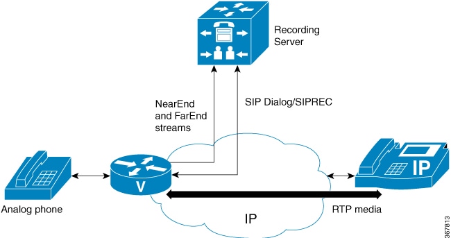
The Media Recording feature is introduced in Cisco IOS XE Gibraltar 16.10.1 release.The Media Recording feature on TDM Gateways uses Digital Signal Processor (DSP) based media forking for Real-time Transport Protocol (RTP) streams. You can record the call by sending a copy of the media streams to the recording server.When you send a copy of the media streams to the recording server, the TDM gateway acts a session recording client, which uses SIP protocol to communicate the recording metadata with the recording server. This call instance that is created between the recording client and recording server is called the recording session. The recording metadata contains the description of the communication session along with the participants of the call and details of the media streams. The recording session comprises of two media streams forked by DSP, one is the near-end stream that enters into the analog phone, and the other far-end stream that is sent to the IP cloud (IP phone in the diagram below).
Cisco 4000 Series platform supports Smart License for Unified Communication (UC) functionality. As the Media Recording feature supports a feature based license, in addition to the existing UC license, you must register to the Smart Licensing portal. Once the feature is registered and the associated license request is granted by the license server, the license is maintained on the gateway. The granted licenses then can be assigned on a per call basis to a analog call that have media recording feature.
Note |
The One License pack enables four analog session recording either for FXS or FXO. |
The media recording session is initiated when a pre-configured set of rules is approved on the telephony leg. These rules include recording license availability and the recording feature configuration.
To record the call, use the media-recording <dial-peer tag> configuration command . It is provisioned under the POTS dial-peer which reflects the telephony leg of a call. In addition, this command also provides the media-recording tag which reflects the SIP VoIP Dial-peer to communicate with the SIP recording server.
There are three different basic TDM gateway usecases that can be considered for media recording:
-
Pots-to-VoIP Call: The call is a standard inbound telephony call which is routed out on the VoIP leg.
-
POTS-to-POTS Call: The call is a standard inbound telephony call which is routed back out on another telephony interface on the same gateway. As there is no VoIP component present for this call, you should use the no local-bypass CLI configuration under voice-card so that a VoIP leg is introduced to help facilitate media recording for the call.
-
VoIP -to-POTS Call: The call is a standard outbound telephony call which is routed in on the VoIP leg.
Restrictions for Media Recording
Time-division Multiplexing (TDM) media recording is not supported for the following calls:
-
TDM-IP calls that do not use Session Initiation Protocol (SIP). Supports limited to basic call scenario for analog endpoints with SIP call control signaling.
-
Supports SIPREC standard for network based recording.
-
DSP forks near and far-end streams. Voice mixing is not considered for forking.
-
Support is limited to basic calls and does not support supplementary services.
-
Recording is not supported if the device is running an IVR application.
-
Multiple destinations recording is not supported. Current support is limited to one recording server destination per call.
-
Simple and complex forking call flows with G.729 and G.711 codecs.
-
The RFC2833 is not supported annd only Inband DTMF forking is supported.
-
Secure calls with SRTP/TLS is not supported with media recording.
Configuring Media Recording
This section describes the steps to configure media recording on Cisco 4000 Series ISRs.
Configuring Media Recording
To configure the media recording:
SUMMARY STEPS
- enable
- configure terminal
- voice service pots
- media-recording licenses <num>
- exit
- dial-peer voice <nnnn> pots
- incoming called-number string
- media-recording dialpeer tag
- port string
- exit
- dial-peer voice dummy-recorder-dial-peer-tag voip
- description dial-peer that needs to be forked
- destination-pattern [+] string [T]
- session protocol sipv2
- session target ipv4 [recording-server-destination-address | recording-server-dns]
- exit
DETAILED STEPS
| Command or Action | Purpose | |
|---|---|---|
|
Step 1 |
enable Example: |
Enables privileged EXEC mode.
|
|
Step 2 |
configure terminal Example: |
Enters global configuration mode. |
|
Step 3 |
voice service pots Example: |
Enters voice service mode for telephony. |
|
Step 4 |
media-recording licenses <num> Example: |
Configures media-recording feature license request count. |
|
Step 5 |
exit Example: |
Exits the dial peer voice configuration mode. |
|
Step 6 |
dial-peer voice <nnnn> pots Example: |
Configures a dial peer and enters dial peer voice configuration mode. |
|
Step 7 |
incoming called-number string Example: |
This dial peer command defines the called number destination or dialed number. |
|
Step 8 |
media-recording dialpeer tag Example: |
This dial peer command is used to enable media recording feature and couple it with the SIP Recorder VoIP dial-peer. |
|
Step 9 |
port string Example: |
This dial peer command defines the POTS voice port through which calls to/from this dial peer are placed. |
|
Step 10 |
exit Example: |
Exits the dial peer voice configuration mode. |
|
Step 11 |
dial-peer voice dummy-recorder-dial-peer-tag voip Example: |
Configures a recorder dial peer and enters dial peer voice configuration mode. |
|
Step 12 |
description dial-peer that needs to be forked Example: |
Provide a descriptionf for the dial-peer that needs to be forked. |
|
Step 13 |
destination-pattern [+] string [T] Example: |
Specifies either the prefix or the full E.164 telephone number (depending on your dial plan) to be used for this dial peer. This is a dummy dial pattern which is not utilized in the actual call routing. |
|
Step 14 |
session protocol sipv2 Example: |
Configures the VoIP dial peer to use Session Initiation Protocol (SIP). |
|
Step 15 |
session target ipv4 [recording-server-destination-address | recording-server-dns] Example: |
Specifies a network-specific address for a dial peer. Keyword and argument are as follows: ipv4: destination address --IP address of the dial peer, in this format: xxx.xxx.xxx.xxx. |
|
Step 16 |
exit Example: |
Exits the dial peer voice configuration mode. |
Enabling Voice-port Recording License
To enable the voice-port recording license, use the media-recording licenses command in the voice service mode. After you enter the configuration, a static license request is raised and a license request is sent to the server. The system looks for the license. If the license is granted, the CLI is execute, otherwise, the CLI is rejected or updated.
-
MR-AUD-4CH
-
MR-AUD-4CH
For more information on smart licensing, see the Cisco 4000 Series ISRs Software Configuration Guide.
The following example shows how to enable the media-recording license:
Device(config)# voice service pots
 Device(conf-voi-serv)# media-recording licenses <1 to 500>
Example: Show Voice Media Recording
To view the media recording configuration enabled on dial-peer and media recording license configuration under the global voice service pots mode, use the show voice media-recording command as shown in this example:
Device# show voice media-recording list
Device#show voice media-recording list

== pa_bay : 5 ==

 Item 0:
  Recording port dialpeer tag   : 500
  Recording server dialpeer tag : 50
  Recording port pa_bay         : 5
  Recording port type           : ANALOG
  Recording port ID             : 1/0/20

Total record : 1
Device# show voice media-recording license
      Recording license configured 100, allocated 100
      Max recording calls allowed 400, Recorded calls in progress 1
Related Documents
|
Related Topic |
Document Title |
|---|---|
|
Installation guide for the Cisco PVDM4 |
|
|
Installation guide for the Cisco Network Interface Module |
|
|
Command reference information for interface and hardware components |
Cisco IOS Interface and Hardware Component Command Reference |
|
Installation of the Cisco 4451-X Series Integrated Services Router |
Hardware Installation Guide for the Cisco 4451-X Integrated Services Router |
|
Comprehensive command reference information for Cisco IOS voice commands |
Cisco Unified Border Element (SP Edition) Command Reference: Unified Model |
|
Configuration guides for different voice and video applications, H.332 networks, SIP devices, and Cisco Voice Gateway Routers. |
Cisco Unified Border Element Configuration Guide Library, Cisco IOS XE Release 3S |
|
System administrator’s guide for Cisco Unified SRST |
|
|
Configuration information for Cisco Voice Gateway Routers that are configured for Cisco Unified Communications Manager |
Cisco Unified Communications Manager and Cisco IOS Interoperability Guide |
|
Regulatory compliance and safety information |
Cisco Network Modules and Interface Cards Regulatory Compliance and Safety Information |
MIBs
|
MIB |
MIBs Link |
|---|---|
|
To locate and download MIBs for selected platforms, Cisco software releases, and feature sets, use Cisco MIB Locator found at the following URL: |
RFCs
|
RFC |
Title |
|---|---|
|
RFC 1315 |
Management Information Base for Frame Delay DTEs |
|
RFC 1406 |
Definitions of Managed Objects for the DS1 and E1 Interface Types |
|
RFC 3261 |
SIP: Session Initiation Protocol |
 Feedback