- Overview of the Cisco 819 Integrated Services Router
- Wireless Device Overview
- Wireless Local Area Network
- 4G LTE Wireless WAN
- Basic Router Configuration
- Configuring Backup Data Lines and Remote Management
- Environment Monitoring
- Configuring the Serial Interface
- Configuring Security Features
- Configuring the Ethernet Switches
- Configuring PPP over Ethernet with NAT
- Configuring a LAN with DHCP and VLANs
- Configuring a VPN Using Easy VPN and an IPSec Tunnel
- Cisco IOS Software Basic Skills
- Concepts
- ROM Monitor
- Common Port Assignments
Cisco 819 Integrated Services Routers Software Configuration Guide
Bias-Free Language
The documentation set for this product strives to use bias-free language. For the purposes of this documentation set, bias-free is defined as language that does not imply discrimination based on age, disability, gender, racial identity, ethnic identity, sexual orientation, socioeconomic status, and intersectionality. Exceptions may be present in the documentation due to language that is hardcoded in the user interfaces of the product software, language used based on RFP documentation, or language that is used by a referenced third-party product. Learn more about how Cisco is using Inclusive Language.
- Updated:
- March 14, 2016
Chapter: Configuring PPP over Ethernet with NAT
Configuring PPP over Ethernet with NAT
This chapter provides an overview of Point-to-Point Protocol over Ethernet (PPPoE) clients and Network Address Translation (NAT) that can be configured on the Cisco 819 Integrated Services Routers (ISRs).
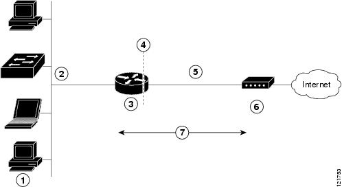
Multiple PCs can be connected to the LAN behind the router. Before the traffic from these PCs is sent to the PPPoE session, it can be encrypted, filtered, and so forth. Figure 11-1 shows a typical deployment scenario with a PPPoE client and NAT configured on the Cisco router.
Figure 11-1 PPP over Ethernet with NAT
|
|
|
|
|
|
|
|
|
|
|
|
|
|
|
|
|
Cable modem or other server that is connected to the Internet |
|
|
PPPoE
The PPPoE Client feature on the router provides PPPoE client support on Ethernet interfaces. A dialer interface must be used for cloning virtual access. Multiple PPPoE client sessions can be configured on an Ethernet interface, but each session must use a separate dialer interface and a separate dialer pool.
A PPPoE session is initiated on the client side by the Cisco 819 ISRs. An established PPPoE client session can be terminated in one of two ways:
- By entering the clear vpdn tunnel pppoe command. The PPPoE client session terminates, and the PPPoE client immediately tries to re-establish the session. This also occurs if the session has a timeout.
- By entering the no pppoe-client dial-pool number command to clear the session. The PPPoE client does not attempt to re-establish the session.
NAT
NAT (represented as the dashed line at the edge of the Cisco router) signifies two addressing domains and the inside source address. The source list defines how the packet travels through the network.
Configuration Tasks
Perform the following tasks to configure this network scenario:
- Configure the Virtual Private Dialup Network Group Number
- Configure the Fast Ethernet WAN Interfaces
- Configure the Dialer Interface
- Configure Network Address Translation
An example showing the results of these configuration tasks is shown in the “Configuration Example” section.
Configure the Virtual Private Dialup Network Group Number
Configuring a virtual private dialup network (VPDN) enables multiple clients to communicate through the router by way of a single IP address.
Complete the following steps to configure a VPDN, starting from the global configuration mode.
SUMMARY STEPS
DETAILED STEPS
Configure the Fast Ethernet WAN Interfaces
In this scenario, the PPPoE client (your Cisco router) communicates over a 10/100 Mbps-Ethernet interface on both the inside and the outside.
Perform these steps to configure the Fast Ethernet WAN interfaces, starting in global configuration mode:
SUMMARY STEPS
2.![]() pppoe-client dial-pool-number number
pppoe-client dial-pool-number number
Configure the Dialer Interface
The dialer interface indicates how to handle traffic from the clients, including, for example, default routing information, the encapsulation protocol, and the dialer pool to use. The dialer interface is also used for cloning virtual access. Multiple PPPoE client sessions can be configured on a Fast Ethernet interface, but each session must use a separate dialer interface and a separate dialer pool.
Complete the following steps to configure a dialer interface for one of the Fast Ethernet LAN interfaces on the router, starting in global configuration mode.
SUMMARY STEPS
1.![]() interface dialer dialer-rotary-group-number
interface dialer dialer-rotary-group-number
4.![]() encapsulation encapsulation-type
encapsulation encapsulation-type
5.![]() ppp authentication { protocol1 [ protocol2 ...]}
ppp authentication { protocol1 [ protocol2 ...]}
9.![]() dialer-list dialer-group protocol protocol-name {permit | deny | list access-list-number | access-group}
dialer-list dialer-group protocol protocol-name {permit | deny | list access-list-number | access-group}
10.![]() ip route prefix mask { interface-type interface-number }
ip route prefix mask { interface-type interface-number }
DETAILED STEPS
|
|
|
|
|---|---|---|
interface dialer dialer-rotary-group-number |
Creates a dialer interface (numbered 0 to 255) and enters interface configuration mode. |
|
|
|
Specifies that the IP address for the interface is obtained through PPP/IPCP (IP Control Protocol) address negotiation. |
|
|
|
Sets the size of the IP maximum transmission unit (MTU). The default minimum is 128 bytes. The maximum for Ethernet is 1492 bytes. |
|
encapsulation encapsulation-type |
Sets the encapsulation type to PPP for the data packets being transmitted and received. |
|
ppp authentication {protocol1 [protocol2...]} |
Sets the PPP authentication method to Challenge Handshake Authentication Protocol (CHAP). For details about this command and additional parameters that can be set, see Cisco IOS Security Command Reference. |
|
|
|
Specifies the dialer pool to use to connect to a specific destination subnetwork. |
|
|
|
Assigns the dialer interface to a dialer group (1 to 10). |
|
|
|
||
dialer-list dialer-group protocol protocol-name {permit | deny | list access-list-number | access-group} |
Creates a dialer list and associates a dial group with it. Packets are then forwarded through the specified interface dialer group. For details about this command and additional parameters that can be set, see Cisco IOS Dial Technologies Command Reference. |
|
ip route prefix mask {interface-type interface-number} |
Sets the IP route for the default gateway for the dialer 0 interface. For details about this command and additional parameters that can be set, see Cisco IOS IP Command Reference, Volume 2 of 3: Routing Protocols, Release 12.2 and Cisco IOS IP Command Reference, Volume 2 of 4: Routing Protocols, Release 12.3. |
Configure Network Address Translation
Network Address Translation (NAT) translates packets from addresses that match a standard access list, using global addresses allocated by the dialer interface. Packets that enter the router through the inside interface, packets sourced from the router, or both are checked against the access list for possible address translation. You can configure NAT for either static or dynamic address translations.
Perform these steps to configure the outside Fast Ethernet WAN interface with dynamic NAT, beginning in global configuration mode:
SUMMARY STEPS
1.![]() ip nat pool name start-ip end-ip {netmask netmask | prefix-length prefix-length }
ip nat pool name start-ip end-ip {netmask netmask | prefix-length prefix-length }
2.![]() ip nat inside source {list access-list-number } {interface type number | pool name } [overload]
ip nat inside source {list access-list-number } {interface type number | pool name } [overload]
11.![]() access-list access-list-number {deny | permit} source [ source-wildcard ]
access-list access-list-number {deny | permit} source [ source-wildcard ]
DETAILED STEPS
|
|
|
|
|---|---|---|
ip nat pool name start-ip end-ip {netmask netmask | prefix-length prefix-length} |
||
ip nat inside source {list access-list-number} {interface type number | pool name} [overload] |
Enables dynamic translation of addresses on the inside interface. The first example shows the addresses permitted by the access list 1 to be translated to one of the addresses specified in the dialer interface 0. The second example shows the addresses permitted by access list acl1 to be translated to one of the addresses specified in the NAT pool pool1. For details about this command and additional parameters that can be set, as well as information about enabling static translation, see Cisco IOS IP Command Reference, Volume 1 of 4: Addressing and Services. |
|
|
|
Enters configuration mode for the VLAN (on which the Fast Ethernet LAN interfaces [FE0–FE3] reside) to be the inside interface for NAT. |
|
|
|
Identifies the specified VLAN interface as the NAT inside interface. For details about this command and additional parameters that can be set, as well as information about enabling static translation, see Cisco IOS IP Command Reference, Volume 1 of 4: Addressing and Services. |
|
|
|
Enables the configuration changes just made to the Ethernet interface. |
|
|
|
||
|
|
Enters configuration mode for the Fast Ethernet WAN interface (FE4) to be the outside interface for NAT. |
|
|
|
Identifies the specified WAN interface as the NAT outside interface. For details about this command and additional parameters that can be set, as well as information about enabling static translation, see Cisco IOS IP Command Reference, Volume 1 of 4: Addressing and Services. |
|
|
|
Enables the configuration changes just made to the Ethernet interface. |
|
|
|
||
access-list access-list-number {deny | permit} source [source-wildcard] |
Defines a standard access list indicating which addresses need translation. |

Note![]() If you want to use NAT with a virtual-template interface, you must configure a loopback interface. See the “Basic Router Configuration” section for information on configuring a loopback interface.
If you want to use NAT with a virtual-template interface, you must configure a loopback interface. See the “Basic Router Configuration” section for information on configuring a loopback interface.
For complete information on the NAT commands, see the Cisco IOS Release 12.3 documentation set. For more general information on NAT concept, see the “Cisco IOS Software Basic Skills” section.
Configuration Example
The following configuration example shows a portion of the configuration file for the PPPoE scenario described in this chapter.
The VLAN interface has an IP address of 192.168.1.1 with a subnet mask of 255.255.255.0. NAT is configured for inside and outside
Note![]() Commands marked by “(default)” are generated automatically when you run the show running-config command.
Commands marked by “(default)” are generated automatically when you run the show running-config command.
vpdn-group 1
request-dialin
protocol pppoe
!
interface vlan 1
ip address 192.168.1.1 255.255.255.0
no ip directed-broadcast (default)
ip nat inside
no ip address
no ip directed-broadcast (default)
ip nat outside
pppoe enable group global
pppoe-client dial-pool-number 1
no sh
interface dialer 0
ip address negotiated
ip mtu 1492
encapsulation ppp
ppp authentication chap
dialer pool 1
dialer-group 1
!
dialer-list 1 protocol ip permit
ip nat inside source list 1 interface dialer 0 overload
ip classless (default)
ip route 10.10.25.2 255.255.255.255 dialer 0
ip nat inside source list acl1 pool pool1
Verifying Your Configuration
Use the show ip nat statistics command in privileged EXEC mode to verify the PPPoE with NAT configuration. You should see verification output similar to the following example:
 Feedback