- Title
- Contents
- Preface
- part 1
- Basic Router Configuration
- part 2
- Sample Network Deployments
- Configuring PPP over Ethernet with NAT
- Configuring PPP over ATM with NAT
- Configuring a LAN with DHCP and VLANs
- Configuring a VPN Using Easy VPN and an IPSec Tunnel
- Configuring VPNs Using an IPSec Tunnel and Generic Routing Encapsulation
- Configuring a Simple Firewall
- Configuring a Wireless LAN Connection
- Sample Configuration
- Additional Configuration Options
- part 3
- Configuring Security Features
- Configuring Dial Backup and Remote Management
- Troubleshooting
- part 4
- Cisco IOS Software Basic Skills
- Concepts
- ROM Monitor
- Common Port Assignments
- Index
Cisco 1800 Series Integrated Services Routers (Fixed) Software Configuration Guide
Bias-Free Language
The documentation set for this product strives to use bias-free language. For the purposes of this documentation set, bias-free is defined as language that does not imply discrimination based on age, disability, gender, racial identity, ethnic identity, sexual orientation, socioeconomic status, and intersectionality. Exceptions may be present in the documentation due to language that is hardcoded in the user interfaces of the product software, language used based on RFP documentation, or language that is used by a referenced third-party product. Learn more about how Cisco is using Inclusive Language.
Chapter: Configuring a Wireless LAN Connection
Configuring a Wireless LAN Connection
The Cisco 1800 series integrated services fixed-configuration routers support a secure, affordable, and easy-to-use wireless LAN solution that combines mobility and flexibility with the enterprise-class features required by networking professionals. With a management system based on Cisco IOS software, the Cisco routers act as access points, and are Wi-Fi certified, IEEE 802.11a/b/g-compliant wireless LAN transceivers.
You can configure and monitor the routers using the command-line interface (CLI), the browser-based management system, or Simple Network Management Protocol (SNMP). This chapter describes how to configure the router using the CLI. Use the interface dot11radio global configuration CLI command to place the device into radio configuration mode.
See the Cisco Access Router Wireless Configuration Guide for more detailed information about configuring these Cisco routers in a wireless LAN application.
Figure 9-1 shows a wireless network deployment.
Figure 9-1 Sample Wireless LAN
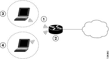
In the configuration example that follows, a remote user is accessing the Cisco 1800 series integrated services router using a wireless connection. Each remote user has his own VLAN.
Perform the following tasks to configure this network scenario:
An example showing the results of these configuration tasks is shown in the section “Configuration Example.”

Note The procedures in this chapter assume that you have already configured basic router features as well as PPPoE or PPPoA with NAT. If you have not performed these configurations tasks, see “Basic Router Configuration,” “Configuring PPP over Ethernet with NAT,” and “Configuring PPP over ATM with NAT,” as appropriate for your router. You may have also configured DHCP, VLANs, and secure tunnels.
Configure the Root Radio Station
Perform these steps to create and configure the root radio station for your wireless LAN, beginning in global configuration mode:
Enters interface configuration mode for the specified wireless interface. |
||
broadcast-key [[ vlan vlan-id ] change secs ] [ membership-termination ] [ capability-change ] |
Specifies the time interval (in seconds) between rotations of the broadcast encryption key used for clients. Note Client devices using static Wired Equivalent Privacy (WEP) cannot use the access point when you enable broadcast key rotation—only wireless client devices using 802.1x authentication (such as Light Extensible Authentication Protocol [LEAP], Extensible Authentication Protocol-Transport Layer Security [EAP-TLS], or Protected Extensible Authentication Protocol [PEAP]) can use the access point. Note This command is not supported on bridges.See the Cisco IOS Commands for Access Points and Bridges document for more details. |
|
Specifies the encryption method, algorithm, and key used to access the wireless interface. The example uses the VLAN with optional encryption method of data ciphers. |
||
Creates a Service Set ID (SSID), the public name of a wireless network. Note All of the wireless devices on a WLAN must employ the same SSID to communicate with each other. |
||
Sets the permitted authentication methods for a user attempting access to the wireless LAN. More than one method can be specified, as shown in the example. |
||
Exits SSID configuration mode, and enters interface configuration mode for the wireless interface. |
||
(Optional) Specifies the required and allowed rates, in Mbps, for traffic over the wireless connection. |
||
(Optional) Specifies the Request to Send (RTS) threshold or the number of times to send a request before determining the wireless LAN is unreachable. |
||
power [ client | local ] [ cck [ number | maximum ] | ofdm [ number | maximum ]] |
(Optional) Specifies the radio transmitter power level. See the Cisco Access Router Wireless Configuration Guide for available power level values. |
|
(Optional) Specifies the channel on which communication occurs. See the Cisco Access Router Wireless Configuration Guide for available channel numbers. |
||
Exits interface configuration mode, and enters global configuration mode. |
Configure Bridging on VLANs
Perform these steps to configure integrated routing and bridging on VLANs, beginning in global configuration mode:
Enters interface configuration mode. We want to set up bridging on the VLANs, so the example enters the VLAN interface configuration mode. |
||
Repeat Step 2 through Step 6 above for each VLAN that requires a wireless interface.
Configure Radio Station Subinterfaces
Perform these steps to configure subinterfaces for each root station, beginning in global configuration mode:
Repeat these steps to configure more subinterfaces, as needed.
 Feedback