- About this Guide
- Chapter 1, Install the Shelf and Backplane Cable
- Chapter 2, Install Cards and Fiber-Optic Cable
- Chapter 3, Connect the PC and Log Into the GUI
- Chapter 4, Turn Up Node
- Chapter 5, Turn Up Network
- Chapter 6, Create Circuits and VT Tunnels
- Chapter 7, Manage Alarms
- Chapter 8, Monitor Performance
- Chapter 9, Manage Circuits
- Chapter 10, Change Node Settings
- Chapter 11, Change Card Settings
- Chapter 12, Upgrade Cards and Spans
- Chapter 13, Upgrade Network Configurations
- Chapter 14, Add and Remove Nodes
- Chapter 15, Maintain the Node
- Chapter 16, Power Down the ONS 15454
- Appendix A, CTC Information and Shortcuts
- Appendix B, Shelf Assembly Specifications
- Appendix C, Network Element Defaults
- Glossary
Cisco ONS 15454 Procedure Guide, Release 4.0
Bias-Free Language
The documentation set for this product strives to use bias-free language. For the purposes of this documentation set, bias-free is defined as language that does not imply discrimination based on age, disability, gender, racial identity, ethnic identity, sexual orientation, socioeconomic status, and intersectionality. Exceptions may be present in the documentation due to language that is hardcoded in the user interfaces of the product software, language used based on RFP documentation, or language that is used by a referenced third-party product. Learn more about how Cisco is using Inclusive Language.
- Updated:
- March 20, 2015
Chapter: Chapter 3, Connect the PC and Log Into the GUI
- Before You Begin
- NTP-A21 Set Up Computer for CTC
- NTP-A22 Set Up CTC Computer to Connect to the ONS 15454
- DLP-A50 Set Up a Windows PC for Craft Connection to an ONS 15454 on the Same Subnet Using Static IP Addresses
- DLP-A51 Set Up a Windows PC for Craft Connection to an ONS 15454 Using DHCP
- DLP-A52 Set Up a Windows PC for Craft Connection to an ONS 15454 Using Automatic Host Detection
- DLP-A53 Set Up a Solaris Workstation for a Craft Connection to an ONS 15454
- DLP-A55 Set Up a Computer for a Corporate LAN Connection
- DLP-A56 Disable Proxy Service Using Internet Explorer (Windows)
- DLP-A57 Disable Proxy Service Using Netscape (Windows and UNIX)
- DLP-A58 Provision Remote Access to the ONS 15454
- NTP-A23 Log into the ONS 15454 GUI
Connect the PC and Log into the GUI
This chapter explains how to connect PCs and workstations to the Cisco ONS 15454 and how to log into Cisco Transport Controller (CTC) software, the Cisco ONS 15454 Operation, Administration, Maintenance and Provisioning (OAM&P) user interface.
Before You Begin
This section lists the chapter procedures (NTPs). Turn to a procedure for applicable tasks (DLPs).
1. ![]() 21 Set Up Computer for CTC—Complete this procedure if your PC or workstation has never been connected to an ONS 15454.
21 Set Up Computer for CTC—Complete this procedure if your PC or workstation has never been connected to an ONS 15454.
2. ![]() 22 Set Up CTC Computer to Connect to the ONS 15454—After your PC or workstation is set up for CTC, complete this procedure to set up your computer to connect to the ONS 15454.
22 Set Up CTC Computer to Connect to the ONS 15454—After your PC or workstation is set up for CTC, complete this procedure to set up your computer to connect to the ONS 15454.
3. ![]() 23 Log into the ONS 15454 GUI—Complete this procedure to log into CTC.
23 Log into the ONS 15454 GUI—Complete this procedure to log into CTC.
NTP-A21 Set Up Computer for CTC
Step 1 ![]() If your computer is a Windows PC, complete the "DLP-A47 Run the CTC Installation Wizard for Windows" task, then go to Step 4.
If your computer is a Windows PC, complete the "DLP-A47 Run the CTC Installation Wizard for Windows" task, then go to Step 4.
Step 2 ![]() If your computer is a UNIX workstation, complete the "DLP-A48 Run the CTC Installation Wizard for UNIX" task.
If your computer is a UNIX workstation, complete the "DLP-A48 Run the CTC Installation Wizard for UNIX" task.
Step 3 ![]() If your computer is a UNIX workstation and you installed the Java Runtime Environment (JRE) in Step 2, complete the "DLP-A49 Set Up the Java Runtime Environment for UNIX" task.
If your computer is a UNIX workstation and you installed the Java Runtime Environment (JRE) in Step 2, complete the "DLP-A49 Set Up the Java Runtime Environment for UNIX" task.
Step 4 ![]() When your PC or workstation is set up, complete the "22 Set Up CTC Computer to Connect to the ONS 15454" procedure.
When your PC or workstation is set up, complete the "22 Set Up CTC Computer to Connect to the ONS 15454" procedure.
Stop. You have completed this procedure.
DLP-A47 Run the CTC Installation Wizard for Windows
Step 1 ![]() Verify that your computer has the following:
Verify that your computer has the following:
•![]() Processor—Pentium II, 300 Mhz or faster.
Processor—Pentium II, 300 Mhz or faster.
•![]() RAM—128 MB.
RAM—128 MB.
•![]() Hard drive—2 GB is recommended. 50 MB of space must be available.
Hard drive—2 GB is recommended. 50 MB of space must be available.
•![]() Operating System—Windows 95, Windows 98, Windows NT 4.0, Windows 2000, or Windows XP.
Operating System—Windows 95, Windows 98, Windows NT 4.0, Windows 2000, or Windows XP.
If your operating system is Windows NT 4.0, verify that Service Pack 5 or later is installed. From the Start menu, choose Programs > Administrative Tools > Windows NT Diagnostics and check the service pack on the Version tab of the Windows NT Diagnostics dialog box. If Service Pack 5 or later is not installed, do not continue. Install Service Pack 5 following the computer upgrade procedures for your site.

Note ![]() Processor and RAM requirements are guidelines. CTC performance is faster if your computer has a faster processor and more RAM. Refer to the Cisco ONS 15454 Reference Manual for computer requirements needed for small, medium, and large ONS 15454 networks.
Processor and RAM requirements are guidelines. CTC performance is faster if your computer has a faster processor and more RAM. Refer to the Cisco ONS 15454 Reference Manual for computer requirements needed for small, medium, and large ONS 15454 networks.
Step 2 ![]() Insert the Cisco ONS 15454 Release 4.0 software or documentation CD into your computer CD drive. The installation program begins running automatically. If it does not start, navigate to your computer's CD directory and double-click setup.exe.
Insert the Cisco ONS 15454 Release 4.0 software or documentation CD into your computer CD drive. The installation program begins running automatically. If it does not start, navigate to your computer's CD directory and double-click setup.exe.
The Cisco Transport Controller Installation Wizard displays the components that will be installed on your computer (Figure 3-1).
Figure 3-1 Cisco Transport Controller Installation Wizard

Step 3 ![]() Click Next.
Click Next.
Step 4 ![]() Choose Typical to install all the components shown in Figure 3-1, or choose Custom if you only want to install some of the components.
Choose Typical to install all the components shown in Figure 3-1, or choose Custom if you only want to install some of the components.
Step 5 ![]() Click Next.
Click Next.
Step 6 ![]() If you selected Custom in Step 4, select the CTC components you want to install and click Next. If you selected Typical, skip this step and proceed to Step 7.
If you selected Custom in Step 4, select the CTC components you want to install and click Next. If you selected Typical, skip this step and proceed to Step 7.
Step 7 ![]() The directory where the installation wizard will install CTC online help is displayed. The default is C:\Program Files\Cisco\CTC\Documentation.
The directory where the installation wizard will install CTC online help is displayed. The default is C:\Program Files\Cisco\CTC\Documentation.
a. ![]() If you do not want to change the directory, skip this step and proceed to Step 8.
If you do not want to change the directory, skip this step and proceed to Step 8.
b. ![]() If you want to change the CTC online help directory, type the new directory path in the Directory Name field, or click Browse to navigate to the directory.
If you want to change the CTC online help directory, type the new directory path in the Directory Name field, or click Browse to navigate to the directory.
Step 8 ![]() Click Next.
Click Next.
Step 9 ![]() Review the components that will be installed. If you want to change them, click Back. If you have an active CTC session (for example, you are monitoring alarms or conditions), close CTC before going to Step 10.
Review the components that will be installed. If you want to change them, click Back. If you have an active CTC session (for example, you are monitoring alarms or conditions), close CTC before going to Step 10.
Step 10 ![]() Click Next.
Click Next.
An Installation Issues dialog box is displayed.
Step 11 ![]() Review the issues, then click OK. The InstallShield program begins the Netscape Communicator 4.73 Setup program.
Review the issues, then click OK. The InstallShield program begins the Netscape Communicator 4.73 Setup program.
Step 12 ![]() Complete the Netscape installation:
Complete the Netscape installation:
a. ![]() In the Netscape Communicator 4.73 Setup dialog box, click Next.
In the Netscape Communicator 4.73 Setup dialog box, click Next.
b. ![]() In the Software License Agreement dialog box, click Yes.
In the Software License Agreement dialog box, click Yes.
c. ![]() In the Setup Type dialog box, click Typical, then click Next.
In the Setup Type dialog box, click Typical, then click Next.
Note ![]() If the Netscape installation hangs when installing RealPlayer G2, restart the CTC installation by pressing Ctrl-Alt-Del. In the Windows Security dialog box, click Task Manager. In the Windows Task Manager dialog box, click Cisco Transport Controller Installation Wizard, then click the End Task button. Click Yes in the confirmation dialog box. Navigate to the drive containing the CTC CD and double-click CTC.exe. Repeat Steps 1 to 11. At Step 12, Step c, click Custom, then click Next. At the next panel, deselect RealPlayer. Continue with Step d.
If the Netscape installation hangs when installing RealPlayer G2, restart the CTC installation by pressing Ctrl-Alt-Del. In the Windows Security dialog box, click Task Manager. In the Windows Task Manager dialog box, click Cisco Transport Controller Installation Wizard, then click the End Task button. Click Yes in the confirmation dialog box. Navigate to the drive containing the CTC CD and double-click CTC.exe. Repeat Steps 1 to 11. At Step 12, Step c, click Custom, then click Next. At the next panel, deselect RealPlayer. Continue with Step d.
d. ![]() In the Netscape Desktop Preferences Options dialog box, check the boxes that apply according to your site requirements (these options do not affect CTC operation), then click Next.
In the Netscape Desktop Preferences Options dialog box, check the boxes that apply according to your site requirements (these options do not affect CTC operation), then click Next.
e. ![]() In the Select Program Folder dialog box, click Next.
In the Select Program Folder dialog box, click Next.
f. ![]() In the Start Copying Files dialog box, click Install. The program begins the Netscape installation.
In the Start Copying Files dialog box, click Install. The program begins the Netscape installation.
g. ![]() In the Question dialog box, click No.
In the Question dialog box, click No.
h. ![]() In the Information dialog box, click OK.
In the Information dialog box, click OK.
i. ![]() In the Restarting Windows dialog box, click No, I will restart later, then click OK.
In the Restarting Windows dialog box, click No, I will restart later, then click OK.
Step 13 ![]() Close the Netscape Communicator directory window to display the Cisco Transport Controller Installation Wizard dialog box.
Close the Netscape Communicator directory window to display the Cisco Transport Controller Installation Wizard dialog box.
Step 14 ![]() In the CTC Installation Wizard dialog box, click Next. The Java 2 runtime environment installation begins.
In the CTC Installation Wizard dialog box, click Next. The Java 2 runtime environment installation begins.
Step 15 ![]() Complete the JRE installation:
Complete the JRE installation:
a. ![]() In the Software License Agreement dialog box, click Yes.
In the Software License Agreement dialog box, click Yes.
b. ![]() In the Choose Destination Location dialog box, click Next.
In the Choose Destination Location dialog box, click Next.
c. ![]() In the Select Browser dialog box, click the Microsoft Internet Explorer and Netscape 6 check boxes, then click Next.
In the Select Browser dialog box, click the Microsoft Internet Explorer and Netscape 6 check boxes, then click Next.
When JRE installation is complete, the Cisco Transport Controller Installation Wizard dialog box is displayed.
Step 16 ![]() Click Next. The CTC online help is installed. When installed, the policy file selection is displayed.
Click Next. The CTC online help is installed. When installed, the policy file selection is displayed.
Step 17 ![]() Choose the JRE policy file to modify:
Choose the JRE policy file to modify:
•![]() Choose User Policy File (default) to modify the policy file that applies only to your user profile. This file is not overwritten if you upgrade or reinstall the JRE. If you are the only user who will access an ONS 15454 from the PC you are setting up, choose this option.
Choose User Policy File (default) to modify the policy file that applies only to your user profile. This file is not overwritten if you upgrade or reinstall the JRE. If you are the only user who will access an ONS 15454 from the PC you are setting up, choose this option.
•![]() Choose System Policy File to modify the system JRE policy file. This policy file applies to all computer users. If more than one individual will use this computer to access the ONS 15454, choose this option. However, if you reinstall or upgrade the JRE, the system policy file is overwritten and you must run the CTC Installation Setup program again to modify it.
Choose System Policy File to modify the system JRE policy file. This policy file applies to all computer users. If more than one individual will use this computer to access the ONS 15454, choose this option. However, if you reinstall or upgrade the JRE, the system policy file is overwritten and you must run the CTC Installation Setup program again to modify it.
Step 18 ![]() Click Next.
Click Next.
Step 19 ![]() If you selected System Policy File in Step 17, complete the following steps. If you selected User Policy File, go to Step 20.
If you selected System Policy File in Step 17, complete the following steps. If you selected User Policy File, go to Step 20.
a. ![]() The System Policy File Update dialog box displays the default policy file location (C:\Program Files\JavaSoft\jre). If you installed the JRE in a different location, enter the new path in the Directory Name field. After entering the path, or if the default path is correct, click OK.
The System Policy File Update dialog box displays the default policy file location (C:\Program Files\JavaSoft\jre). If you installed the JRE in a different location, enter the new path in the Directory Name field. After entering the path, or if the default path is correct, click OK.
b. ![]() Click OK in the confirmation dialog box.
Click OK in the confirmation dialog box.
Step 20 ![]() Click Finish.
Click Finish.
Step 21 ![]() Return to your originating procedure (NTP).
Return to your originating procedure (NTP).
DLP-A48 Run the CTC Installation Wizard for UNIX
Step 1 ![]() Verify that your computer has the following:
Verify that your computer has the following:
•![]() RAM—128 MB.
RAM—128 MB.
•![]() Hard drive—Verify that 50 MB of space is available.
Hard drive—Verify that 50 MB of space is available.
•![]() Operating System—Solaris 2.5.x or 2.6.x.
Operating System—Solaris 2.5.x or 2.6.x.
Note ![]() These requirements are guidelines. CTC performance is faster if your computer has a faster processor and more RAM. Refer to the Cisco ONS 15454 Reference Manual for computer requirements needed for small, medium, and large ONS 15454 networks.
These requirements are guidelines. CTC performance is faster if your computer has a faster processor and more RAM. Refer to the Cisco ONS 15454 Reference Manual for computer requirements needed for small, medium, and large ONS 15454 networks.
Step 2 ![]() Change the directory, type:
Change the directory, type:
cd /cdrom/cdrom0/
Step 3 ![]() From the techdoc454 CD directory, type:
From the techdoc454 CD directory, type:
./setup.bat
The Cisco Transport Controller Installation Wizard displays the components that will be installed on your computer (Figure 3-1):
•![]() Netscape Communicator 4.76.
Netscape Communicator 4.76.
•![]() Java Runtime Environment 1.3.1_02.
Java Runtime Environment 1.3.1_02.
•![]() CTC Online Help.
CTC Online Help.
•![]() Modify Policy File—The JRE java.policy file is modified to enable CTC to download files needed to run the Cisco Transport Controller when you connect to an ONS 15454.
Modify Policy File—The JRE java.policy file is modified to enable CTC to download files needed to run the Cisco Transport Controller when you connect to an ONS 15454.
Step 4 ![]() Click Next.
Click Next.
Step 5 ![]() Choose Typical to install all components, or choose Custom if you want to choose particular components to install.
Choose Typical to install all components, or choose Custom if you want to choose particular components to install.
Step 6 ![]() Click Next.
Click Next.
Step 7 ![]() If you selected Custom in Step 5, choose the CTC components you want to install and click Next. If you selected Typical, proceed to Step 8.
If you selected Custom in Step 5, choose the CTC components you want to install and click Next. If you selected Typical, proceed to Step 8.
Step 8 ![]() The directory where the installation wizard will install CTC online help is displayed. The default is C:\Program Files\Cisco\CTC\Documentation. If you want to change the CTC online help directory, type the new directory path in the Directory Name field, or click Browse to navigate to the directory.
The directory where the installation wizard will install CTC online help is displayed. The default is C:\Program Files\Cisco\CTC\Documentation. If you want to change the CTC online help directory, type the new directory path in the Directory Name field, or click Browse to navigate to the directory.
Step 9 ![]() Click Next.
Click Next.
Step 10 ![]() Review the components that will be installed. If you want to change them, click Back. If CTC is running (for example, you are reinstalling components) close CTC before going to the next step.
Review the components that will be installed. If you want to change them, click Back. If CTC is running (for example, you are reinstalling components) close CTC before going to the next step.
Step 11 ![]() Click Next. The InstallShield program begins the Netscape Communicator 4.76 Setup program.
Click Next. The InstallShield program begins the Netscape Communicator 4.76 Setup program.
Step 12 ![]() Complete the Netscape installation:
Complete the Netscape installation:
a. ![]() In the Netscape Communicator 4.76 Setup dialog box, click Next.
In the Netscape Communicator 4.76 Setup dialog box, click Next.
b. ![]() In the Software License Agreement dialog box, click Yes.
In the Software License Agreement dialog box, click Yes.
c. ![]() In the Setup Type dialog box, click Typical.
In the Setup Type dialog box, click Typical.
d. ![]() In the Netscape Desktop Preferences dialog box, check the boxes that apply, then click Next.
In the Netscape Desktop Preferences dialog box, check the boxes that apply, then click Next.
e. ![]() In the Program Folder dialog box, click Next.
In the Program Folder dialog box, click Next.
f. ![]() In the Start Copying Files dialog box, click Install. The program begins the Netscape installation.
In the Start Copying Files dialog box, click Install. The program begins the Netscape installation.
g. ![]() In the Question dialog box, click No.
In the Question dialog box, click No.
Step 13 ![]() In the Cisco Transport Controller Installation Wizard dialog box, click Next. The Java 2 runtime environment installation begins.
In the Cisco Transport Controller Installation Wizard dialog box, click Next. The Java 2 runtime environment installation begins.
Step 14 ![]() Complete the JRE installation:
Complete the JRE installation:
a. ![]() In the Software License Agreement dialog box, click Yes.
In the Software License Agreement dialog box, click Yes.
b. ![]() In the Choose Destination Location dialog box, click Next.
In the Choose Destination Location dialog box, click Next.
c. ![]() In the Select Browser dialog box, click the Netscape 6 check box, then click Next.
In the Select Browser dialog box, click the Netscape 6 check box, then click Next.
When JRE installation is complete, the Cisco Transport Controller Installation Wizard dialog box is displayed.
Step 15 ![]() Click Next. The CTC online help is installed. When installed, the policy file selection is displayed.
Click Next. The CTC online help is installed. When installed, the policy file selection is displayed.
Step 16 ![]() Choose the JRE policy file to modify:
Choose the JRE policy file to modify:
•![]() Choose User Policy File (default) to modify a policy file that applies only to your user profile. This file is not overwritten if you upgrade or reinstall the JRE. If you are the only computer user who will access an ONS 15454, choose this option.
Choose User Policy File (default) to modify a policy file that applies only to your user profile. This file is not overwritten if you upgrade or reinstall the JRE. If you are the only computer user who will access an ONS 15454, choose this option.
•![]() Choose System Policy File to modify the system JRE policy file. This policy file applies to all computer users. If more than one individual will use this computer to access the ONS 15454, choose this option. However, if you reinstall or upgrade the JRE, the system policy file is overwritten and you must run the CTC Installation Setup program again to modify it.
Choose System Policy File to modify the system JRE policy file. This policy file applies to all computer users. If more than one individual will use this computer to access the ONS 15454, choose this option. However, if you reinstall or upgrade the JRE, the system policy file is overwritten and you must run the CTC Installation Setup program again to modify it.
Step 17 ![]() Click Next, then click Finish.
Click Next, then click Finish.
Note ![]() Be sure to record the names of the directories you choose for Netscape, JRE, and the online documentation.
Be sure to record the names of the directories you choose for Netscape, JRE, and the online documentation.
Step 18 ![]() Return to your originating procedure (NTP).
Return to your originating procedure (NTP).
DLP-A49 Set Up the Java Runtime Environment for UNIX
Note ![]() The JRE might require certain patches to run properly. The patch tar file can be found in the JRE/Solaris directory on the CD. Please read the JRE/Solaris/Solaris.txt file for more information. In addition to installing any needed patches, set up the JRE for use with Cisco Transport Controller on your UNIX system.
The JRE might require certain patches to run properly. The patch tar file can be found in the JRE/Solaris directory on the CD. Please read the JRE/Solaris/Solaris.txt file for more information. In addition to installing any needed patches, set up the JRE for use with Cisco Transport Controller on your UNIX system.
Note ![]() CTC requires that the location of xterm is also in your path. If you have moved xterm from its default location, /usr/openwin/bin, you must change all occurrences of /usr/openwin/bin in the following procedures to reflect the actual path where xterm exists on your system.
CTC requires that the location of xterm is also in your path. If you have moved xterm from its default location, /usr/openwin/bin, you must change all occurrences of /usr/openwin/bin in the following procedures to reflect the actual path where xterm exists on your system.
Step 1 ![]() Set up the environment variable:
Set up the environment variable:
a. ![]() If you are using the csh shell, edit the .cshrc file in your home directory by appending the file with the lines:
If you are using the csh shell, edit the .cshrc file in your home directory by appending the file with the lines:
setenv JRE JRE-path
setenv NETSCAPE Netscape-path
setenv NPX_PLUGIN_PATH $JRE/j2re1_3_1_02/plugin/sparc/ns4
set path = ( /usr/openwin/bin $NETSCAPE $path )
b. ![]() If you are using the ksh or bash shell, edit the .profile file in your home directory by appending the file with the lines:
If you are using the ksh or bash shell, edit the .profile file in your home directory by appending the file with the lines:
JRE=JRE-path
NETSCAPE=Netscape-path
NPX_PLUGIN_PATH=$JRE/j2re1_3_1_02/plugin/sparc/ns4
PATH=/usr/openwin/bin:$NETSCAPE:$PATH
export JRE NPX_PLUGIN_PATH PATH
Step 2 ![]() Set the JRE reference:
Set the JRE reference:
a. ![]() Run the Control Panel by typing:
Run the Control Panel by typing:
JRE-path/j2re1_3_0_02/bin/ControlPanel
b. ![]() Click the Advanced tab.
Click the Advanced tab.
c. ![]() From the combo box, select JRE-path/j2re1_3_1_02. If the JRE is not found, select other and enter the following in the Path text box:
From the combo box, select JRE-path/j2re1_3_1_02. If the JRE is not found, select other and enter the following in the Path text box:
JRE-path/j2re1_3_1_02
d. ![]() Click Apply.
Click Apply.
Note ![]() If you are running multiple shells, before your new environment variable is set you might need to invoke the same shell for which you changed the initialization file. For example, if you added the environment variable to the .cshrc file, you must run your browser under the csh shell.
If you are running multiple shells, before your new environment variable is set you might need to invoke the same shell for which you changed the initialization file. For example, if you added the environment variable to the .cshrc file, you must run your browser under the csh shell.
Step 3 ![]() Return to your originating procedure (NTP).
Return to your originating procedure (NTP).
NTP-A22 Set Up CTC Computer to Connect to the ONS 15454
Step 1 ![]() From Table 3-1, select the ONS 15454 connection type that you want to set up for your computer.
From Table 3-1, select the ONS 15454 connection type that you want to set up for your computer.
Note ![]() For initial shelf turn up, you should connect your PC directly to the LAN port on the TCC+/TCC2 card of the ONS 15454.
For initial shelf turn up, you should connect your PC directly to the LAN port on the TCC+/TCC2 card of the ONS 15454.
Step 2 ![]() If you need to set up your computer for corporate LAN access, complete the "DLP-A55 Set Up a Computer for a Corporate LAN Connection" task. If not, proceed to the next step.
If you need to set up your computer for corporate LAN access, complete the "DLP-A55 Set Up a Computer for a Corporate LAN Connection" task. If not, proceed to the next step.
Step 3 ![]() If you need to set up the computer for remote access, complete the "DLP-A58 Provision Remote Access to the ONS 15454" task. If not, proceed to the next step.
If you need to set up the computer for remote access, complete the "DLP-A58 Provision Remote Access to the ONS 15454" task. If not, proceed to the next step.
Step 4 ![]() If you need to set up your computer for TL1 access, refer to the Cisco ONS 15454 and Cisco ONS 15327 TL1 Command Guide. If not, proceed to the next step.
If you need to set up your computer for TL1 access, refer to the Cisco ONS 15454 and Cisco ONS 15327 TL1 Command Guide. If not, proceed to the next step.
Step 5 ![]() If you need to set up your computer for local craft connections, choose a task from Table 3-2.
If you need to set up your computer for local craft connections, choose a task from Table 3-2.
|
|
|
|---|---|
• |
Complete this task if: • • • • |
Complete one of these tasks if: • • • |
|
• |
Complete one of these tasks if: • • • |
• |
Complete this task if: • • |
Stop. You have completed this procedure.
DLP-A50 Set Up a Windows PC for Craft Connection to an ONS 15454 on the Same Subnet Using Static IP Addresses
Step 1 ![]() Verify the operating system that is installed on your computer:
Verify the operating system that is installed on your computer:
a. ![]() From the Windows Start menu, choose Settings > Control Panel.
From the Windows Start menu, choose Settings > Control Panel.
b. ![]() In the Control Panel window, double-click the System icon.
In the Control Panel window, double-click the System icon.
c. ![]() On the General tab of the System Settings window, verify that the Windows operating system is one of the following: Windows 95, Windows 98, Windows NT 4.0, Windows 2000, or Windows XP.
On the General tab of the System Settings window, verify that the Windows operating system is one of the following: Windows 95, Windows 98, Windows NT 4.0, Windows 2000, or Windows XP.
Step 2 ![]() If you have Windows 95 or 98 installed on your PC, complete the following steps:
If you have Windows 95 or 98 installed on your PC, complete the following steps:
a. ![]() From the Windows Start menu, choose Settings > Control Panel.
From the Windows Start menu, choose Settings > Control Panel.
b. ![]() In the Control Panel dialog box, click the Network icon.
In the Control Panel dialog box, click the Network icon.
c. ![]() In the Network dialog box, select TCP/IP for your PC Ethernet card, then click Properties.
In the Network dialog box, select TCP/IP for your PC Ethernet card, then click Properties.
d. ![]() In the TCP/IP Properties dialog box, click the DNS Configuration tab and choose Disable DNS.
In the TCP/IP Properties dialog box, click the DNS Configuration tab and choose Disable DNS.
e. ![]() Click the WINS Configuration tab and choose Disable WINS Resolution.
Click the WINS Configuration tab and choose Disable WINS Resolution.
f. ![]() Click the IP Address tab.
Click the IP Address tab.
g. ![]() In the IP Address window, click Specify an IP address.
In the IP Address window, click Specify an IP address.
h. ![]() In the IP Address field, enter an IP address that is identical to the ONS 15454 IP address except for the last three digits. The last three digits must be between 1 and 254. This IP address can be displayed on the LCD. Software R4.0 allows suppressing the LCD IP address display.
In the IP Address field, enter an IP address that is identical to the ONS 15454 IP address except for the last three digits. The last three digits must be between 1 and 254. This IP address can be displayed on the LCD. Software R4.0 allows suppressing the LCD IP address display.
i. ![]() In the Subnet Mask field, type the same subnet mask as the ONS 15454. The default is 255.255.255.0 (24 bit).
In the Subnet Mask field, type the same subnet mask as the ONS 15454. The default is 255.255.255.0 (24 bit).
j. ![]() Click OK.
Click OK.
k. ![]() In the TCP/IP dialog box, click the Gateway tab.
In the TCP/IP dialog box, click the Gateway tab.
l. ![]() In the New Gateway field, type the ONS 15454 IP address. Click Add.
In the New Gateway field, type the ONS 15454 IP address. Click Add.
m. ![]() Verify that the IP address appears in the Installed Gateways field, then click OK.
Verify that the IP address appears in the Installed Gateways field, then click OK.
n. ![]() When the prompt to restart your PC appears, click Yes.
When the prompt to restart your PC appears, click Yes.
Step 3 ![]() If you have Windows NT 4.0 installed on your PC, complete the following steps:
If you have Windows NT 4.0 installed on your PC, complete the following steps:
a. ![]() From the Windows Start menu, choose Settings > Control Panel.
From the Windows Start menu, choose Settings > Control Panel.
b. ![]() In the Control Panel dialog box, click the Network icon.
In the Control Panel dialog box, click the Network icon.
c. ![]() In the Network dialog box, click the Protocols tab, choose TCP/IP Protocol, then click Properties.
In the Network dialog box, click the Protocols tab, choose TCP/IP Protocol, then click Properties.
d. ![]() Click the IP Address tab.
Click the IP Address tab.
e. ![]() In the IP Address window, click Specify an IP address.
In the IP Address window, click Specify an IP address.
f. ![]() In the IP Address field, enter an IP address that is identical to the ONS 15454 IP address shown on the ONS 15454 LCD except for the last three digits. The last three digits must be between 1 and 254.
In the IP Address field, enter an IP address that is identical to the ONS 15454 IP address shown on the ONS 15454 LCD except for the last three digits. The last three digits must be between 1 and 254.
g. ![]() In the Subnet Mask field, type 255.255.255.0.
In the Subnet Mask field, type 255.255.255.0.
h. ![]() Click the Advanced button.
Click the Advanced button.
i. ![]() Under the Gateways List, click Add. The TCP/IP Gateway Address dialog box is displayed.
Under the Gateways List, click Add. The TCP/IP Gateway Address dialog box is displayed.
j. ![]() Type the ONS 15454 IP address in the Gateway Address field.
Type the ONS 15454 IP address in the Gateway Address field.
k. ![]() Click Add.
Click Add.
l. ![]() Click OK.
Click OK.
m. ![]() Click Apply.
Click Apply.
n. ![]() In some cases, Windows NT 4.0 prompts you to reboot your PC. If you receive this prompt, click Yes.
In some cases, Windows NT 4.0 prompts you to reboot your PC. If you receive this prompt, click Yes.
Step 4 ![]() If you have Windows 2000 installed on your PC, complete the following steps:
If you have Windows 2000 installed on your PC, complete the following steps:
a. ![]() From the Windows Start menu, choose Settings > Network and Dial-up Connections > Local Area Connection.
From the Windows Start menu, choose Settings > Network and Dial-up Connections > Local Area Connection.
b. ![]() In the Local Area Connection Status dialog box, click Properties.
In the Local Area Connection Status dialog box, click Properties.
c. ![]() On the General tab, choose Internet Protocol (TCP/IP), then click Properties.
On the General tab, choose Internet Protocol (TCP/IP), then click Properties.
d. ![]() Click Use the following IP address.
Click Use the following IP address.
e. ![]() In the IP Address field, enter an IP address that is identical to the ONS 15454 IP address shown on the ONS 15454 LCD except for the last three digits. The last three digits must be between 1 and 254.
In the IP Address field, enter an IP address that is identical to the ONS 15454 IP address shown on the ONS 15454 LCD except for the last three digits. The last three digits must be between 1 and 254.
f. ![]() In the Subnet Mask field, type 255.255.255.0.
In the Subnet Mask field, type 255.255.255.0.
g. ![]() In the Default Gateway field, type the ONS 15454 IP address.
In the Default Gateway field, type the ONS 15454 IP address.
h. ![]() Click OK.
Click OK.
i. ![]() In the Local Area Connection Properties dialog box, click OK.
In the Local Area Connection Properties dialog box, click OK.
j. ![]() In the Local Area Connection Status dialog box, click Close.
In the Local Area Connection Status dialog box, click Close.
Step 5 ![]() If you have Windows XP installed on your PC, complete the following steps:
If you have Windows XP installed on your PC, complete the following steps:
a. ![]() From the Windows Start menu, choose Control Panel > Network Connections.
From the Windows Start menu, choose Control Panel > Network Connections.
Note ![]() If the Network Connections menu is not available, click Switch to Classic View.
If the Network Connections menu is not available, click Switch to Classic View.
b. ![]() From the Network Connections dialog box, click the Local Area Connection icon.
From the Network Connections dialog box, click the Local Area Connection icon.
c. ![]() From the Local Area Connection Properties dialog box, choose Internet Protocol (TCP/IP), then click Properties.
From the Local Area Connection Properties dialog box, choose Internet Protocol (TCP/IP), then click Properties.
d. ![]() In the IP Address field, enter an IP address that is identical to the ONS 15454 IP address shown on the ONS 15454 LCD except for the last three digits. The last three digits must be between 1 and 254.
In the IP Address field, enter an IP address that is identical to the ONS 15454 IP address shown on the ONS 15454 LCD except for the last three digits. The last three digits must be between 1 and 254.
e. ![]() In the Subnet Mask field, type 255.255.255.0.
In the Subnet Mask field, type 255.255.255.0.
f. ![]() In the Default Gateway field, type the ONS 15454 IP address.
In the Default Gateway field, type the ONS 15454 IP address.
g. ![]() Click OK.
Click OK.
h. ![]() In the Local Area Connection Properties dialog box, click OK.
In the Local Area Connection Properties dialog box, click OK.
i. ![]() In the Local Area Connection Status dialog box, click Close.
In the Local Area Connection Status dialog box, click Close.
Step 6 ![]() Return to your originating procedure (NTP).
Return to your originating procedure (NTP).
DLP-A51 Set Up a Windows PC for Craft Connection to an ONS 15454 Using DHCP

Step 1 ![]() Verify the operating system that is installed on your computer:
Verify the operating system that is installed on your computer:
a. ![]() From the Windows Start menu, choose Settings > Control Panel.
From the Windows Start menu, choose Settings > Control Panel.
b. ![]() In the Control Panel window, double-click the System icon.
In the Control Panel window, double-click the System icon.
c. ![]() On the General tab of the System Settings window, verify that the Windows operating system is one of the following: Windows 95, Windows 98, Windows NT 4.0, Windows 2000, or Windows XP.
On the General tab of the System Settings window, verify that the Windows operating system is one of the following: Windows 95, Windows 98, Windows NT 4.0, Windows 2000, or Windows XP.
Step 2 ![]() If you have Windows 95 or 98 installed on your PC, complete the following steps:
If you have Windows 95 or 98 installed on your PC, complete the following steps:
a. ![]() From the Windows Start menu, choose Settings > Control Panel.
From the Windows Start menu, choose Settings > Control Panel.
b. ![]() In the Control Panel dialog box, click the Network icon.
In the Control Panel dialog box, click the Network icon.
c. ![]() In the Network dialog box, select TCP/IP for your PC Ethernet card, then click Properties.
In the Network dialog box, select TCP/IP for your PC Ethernet card, then click Properties.
d. ![]() In the TCP/IP Properties dialog box, click the DNS Configuration tab and choose Disable DNS.
In the TCP/IP Properties dialog box, click the DNS Configuration tab and choose Disable DNS.
e. ![]() Click the WINS Configuration tab and choose Disable WINS Resolution.
Click the WINS Configuration tab and choose Disable WINS Resolution.
f. ![]() Click the IP Address tab.
Click the IP Address tab.
g. ![]() In the IP Address window, click Obtain an IP address from a DHCP Server.
In the IP Address window, click Obtain an IP address from a DHCP Server.
h. ![]() Click OK.
Click OK.
i. ![]() When the prompt to restart your PC appears, click Yes.
When the prompt to restart your PC appears, click Yes.
Step 3 ![]() If you have Windows NT 4.0 installed on your PC, complete the following steps:
If you have Windows NT 4.0 installed on your PC, complete the following steps:
a. ![]() From the Windows Start menu, choose Settings > Control Panel.
From the Windows Start menu, choose Settings > Control Panel.
b. ![]() In the Control Panel dialog box, click the Network icon.
In the Control Panel dialog box, click the Network icon.
c. ![]() In the Network dialog box, click the Protocols tab, choose TCP/IP Protocol, then click Properties.
In the Network dialog box, click the Protocols tab, choose TCP/IP Protocol, then click Properties.
d. ![]() Click the IP Address tab.
Click the IP Address tab.
e. ![]() In the IP Address window, click Obtain an IP address from a DHCP Server.
In the IP Address window, click Obtain an IP address from a DHCP Server.
f. ![]() Click OK.
Click OK.
g. ![]() Click Apply.
Click Apply.
h. ![]() If Windows prompts you to restart your PC, click Yes.
If Windows prompts you to restart your PC, click Yes.
Step 4 ![]() If you have Windows 2000 installed on your PC, complete the following steps:
If you have Windows 2000 installed on your PC, complete the following steps:
a. ![]() From the Windows Start menu, choose Settings > Network and Dial-up Connections > Local Area Connection.
From the Windows Start menu, choose Settings > Network and Dial-up Connections > Local Area Connection.
b. ![]() In the Local Area Connection Status dialog box, click Properties.
In the Local Area Connection Status dialog box, click Properties.
c. ![]() On the General tab, choose Internet Protocol (TCP/IP), then click Properties.
On the General tab, choose Internet Protocol (TCP/IP), then click Properties.
d. ![]() Click Obtain an IP address from a DHCP Server.
Click Obtain an IP address from a DHCP Server.
e. ![]() Click OK.
Click OK.
f. ![]() In the Local Area Connection Properties dialog box, click OK.
In the Local Area Connection Properties dialog box, click OK.
g. ![]() In the Local Area Connection Status dialog box, click Close.
In the Local Area Connection Status dialog box, click Close.
Step 5 ![]() If you have Windows XP installed on your PC, complete the following steps:
If you have Windows XP installed on your PC, complete the following steps:
a. ![]() From the Windows Start menu, choose Control Panel > Network Connections.
From the Windows Start menu, choose Control Panel > Network Connections.
Note ![]() If the Network Connections menu is not available, click Switch to Classic View.
If the Network Connections menu is not available, click Switch to Classic View.
b. ![]() In the Network Connections dialog box, click Local Area Connection.
In the Network Connections dialog box, click Local Area Connection.
c. ![]() In the Local Area Connection Status dialog box, click Properties.
In the Local Area Connection Status dialog box, click Properties.
d. ![]() On the General tab, choose Internet Protocol (TCP/IP), then click Properties.
On the General tab, choose Internet Protocol (TCP/IP), then click Properties.
e. ![]() Click Obtain an IP address automatically.
Click Obtain an IP address automatically.
f. ![]() Click OK.
Click OK.
g. ![]() In the Local Area Connection Properties dialog box, click OK.
In the Local Area Connection Properties dialog box, click OK.
h. ![]() In the Local Area Connection Status dialog box, click Close.
In the Local Area Connection Status dialog box, click Close.
Step 6 ![]() Return to your originating procedure (NTP).
Return to your originating procedure (NTP).
DLP-A52 Set Up a Windows PC for Craft Connection to an ONS 15454 Using Automatic Host Detection
Note ![]() If you are using automatic host detection and you disconnect a straight-through (Category 5) LAN cable from one node and connect it to another node, you must close CTC and relaunch it to reconnect to the proxy server and communicate with the new node.
If you are using automatic host detection and you disconnect a straight-through (Category 5) LAN cable from one node and connect it to another node, you must close CTC and relaunch it to reconnect to the proxy server and communicate with the new node.
Step 1 ![]() Verify the operating system that is installed on your computer:
Verify the operating system that is installed on your computer:
a. ![]() From the Windows Start menu, choose Settings > Control Panel.
From the Windows Start menu, choose Settings > Control Panel.
Note ![]() In Windows XP, you can select Control Panel directly from the Start menu. Make sure you are in Classic View before continuing with this procedure.
In Windows XP, you can select Control Panel directly from the Start menu. Make sure you are in Classic View before continuing with this procedure.
b. ![]() In the Control Panel window, double-click the System icon.
In the Control Panel window, double-click the System icon.
c. ![]() On the General tab of the System Settings window, verify that the Windows operating system is one of the following: Windows 95, Windows 98, Windows NT 4.0, Windows 2000, or Windows XP.
On the General tab of the System Settings window, verify that the Windows operating system is one of the following: Windows 95, Windows 98, Windows NT 4.0, Windows 2000, or Windows XP.
Step 2 ![]() If you have Windows 95 or 98 installed on your PC, complete the following steps:
If you have Windows 95 or 98 installed on your PC, complete the following steps:
a. ![]() From the Windows Start menu, choose Settings > Control Panel.
From the Windows Start menu, choose Settings > Control Panel.
b. ![]() In the Control Panel dialog box, click the Network icon.
In the Control Panel dialog box, click the Network icon.
c. ![]() In the Network dialog box, select TCP/IP for your PC Ethernet card, then click Properties.
In the Network dialog box, select TCP/IP for your PC Ethernet card, then click Properties.
d. ![]() In the TCP/IP Properties dialog box, click the DNS Configuration tab and choose Disable DNS.
In the TCP/IP Properties dialog box, click the DNS Configuration tab and choose Disable DNS.
e. ![]() Click the WINS Configuration tab and choose Disable WINS Resolution.
Click the WINS Configuration tab and choose Disable WINS Resolution.
f. ![]() Click the IP Address tab.
Click the IP Address tab.
g. ![]() In the IP Address window, click Specify an IP address.
In the IP Address window, click Specify an IP address.
h. ![]() In the IP Address field, enter any legitimate IP address other than the node IP address as indicated on the LCD of the ONS 15454.
In the IP Address field, enter any legitimate IP address other than the node IP address as indicated on the LCD of the ONS 15454.
i. ![]() In the Subnet Mask field, type the same subnet mask as the ONS 15454. The default is 255.255.255.0 (24 bit).
In the Subnet Mask field, type the same subnet mask as the ONS 15454. The default is 255.255.255.0 (24 bit).
j. ![]() Click OK.
Click OK.
k. ![]() In the TCP/IP dialog box, click the Gateway tab.
In the TCP/IP dialog box, click the Gateway tab.
l. ![]() In the New Gateway field, type the address entered in Step f. Click Add.
In the New Gateway field, type the address entered in Step f. Click Add.
m. ![]() Verify that the IP address appears in the Installed Gateways field, then click OK.
Verify that the IP address appears in the Installed Gateways field, then click OK.
n. ![]() When the prompt to restart your PC appears, click Yes.
When the prompt to restart your PC appears, click Yes.
Step 3 ![]() If you have Windows NT 4.0 installed on your PC, complete the following steps:
If you have Windows NT 4.0 installed on your PC, complete the following steps:
a. ![]() From the Windows Start menu, choose Settings > Control Panel.
From the Windows Start menu, choose Settings > Control Panel.
b. ![]() In the Control Panel dialog box, click the Network icon.
In the Control Panel dialog box, click the Network icon.
c. ![]() In the Network dialog box, click the Protocols tab, choose TCP/IP Protocol, then click Properties.
In the Network dialog box, click the Protocols tab, choose TCP/IP Protocol, then click Properties.
d. ![]() Click the IP Address tab.
Click the IP Address tab.
e. ![]() In the IP Address window, click Specify an IP address.
In the IP Address window, click Specify an IP address.
f. ![]() In the IP Address field, enter any legitimate IP address other than the node IP address as indicated on the LCD of the ONS 15454.
In the IP Address field, enter any legitimate IP address other than the node IP address as indicated on the LCD of the ONS 15454.
g. ![]() In the Subnet Mask field, type the same subnet mask as the ONS 15454. The default is 255.255.255.0 (24 bit).
In the Subnet Mask field, type the same subnet mask as the ONS 15454. The default is 255.255.255.0 (24 bit).
h. ![]() Click the Advanced button.
Click the Advanced button.
i. ![]() Under the Gateways List, click Add. The TCP/IP Gateway Address dialog box is displayed.
Under the Gateways List, click Add. The TCP/IP Gateway Address dialog box is displayed.
j. ![]() Type the IP address entered in Step f in the Gateway Address field.
Type the IP address entered in Step f in the Gateway Address field.
k. ![]() Click Add.
Click Add.
l. ![]() Click OK.
Click OK.
m. ![]() Click Apply.
Click Apply.
n. ![]() Reboot your PC.
Reboot your PC.
Step 4 ![]() If you have Windows 2000 installed on your PC, complete the following steps:
If you have Windows 2000 installed on your PC, complete the following steps:
a. ![]() From the Windows Start menu, choose Settings > Network and Dial-up Connections > Local Area Connection.
From the Windows Start menu, choose Settings > Network and Dial-up Connections > Local Area Connection.
b. ![]() In the Local Area Connection Status dialog box, click Properties.
In the Local Area Connection Status dialog box, click Properties.
c. ![]() On the General tab, choose Internet Protocol (TCP/IP), then click Properties.
On the General tab, choose Internet Protocol (TCP/IP), then click Properties.
d. ![]() Click Use the following IP address.
Click Use the following IP address.
e. ![]() In the IP Address field, enter any legitimate IP address other than the node IP address as indicated on the LCD of the ONS 15454.
In the IP Address field, enter any legitimate IP address other than the node IP address as indicated on the LCD of the ONS 15454.
f. ![]() In the Subnet Mask field, type the same subnet mask as the ONS 15454. The default is 255.255.255.0 (24 bit).
In the Subnet Mask field, type the same subnet mask as the ONS 15454. The default is 255.255.255.0 (24 bit).
g. ![]() Type the IP address entered in Step e in the Gateway Address field.
Type the IP address entered in Step e in the Gateway Address field.
h. ![]() Click OK.
Click OK.
i. ![]() In the Local Area Connection Properties dialog box, click OK.
In the Local Area Connection Properties dialog box, click OK.
j. ![]() In the Local Area Connection Status dialog box, click Close.
In the Local Area Connection Status dialog box, click Close.
Step 5 ![]() If you have Windows XP installed on your PC, complete the following steps:
If you have Windows XP installed on your PC, complete the following steps:
a. ![]() From the Windows Start menu, choose Control Panel > Network Connections.
From the Windows Start menu, choose Control Panel > Network Connections.
Note ![]() If the Network Connections menu is not available, click Switch to Classic View.
If the Network Connections menu is not available, click Switch to Classic View.
b. ![]() From the Network Connections dialog box, click the Local Area Connection icon.
From the Network Connections dialog box, click the Local Area Connection icon.
c. ![]() From the Local Area Connection Properties dialog box, choose Internet Protocol (TCP/IP), then click Properties.
From the Local Area Connection Properties dialog box, choose Internet Protocol (TCP/IP), then click Properties.
d. ![]() In the IP Address field, enter any legitimate IP address other than the node IP address as indicated on the LCD of the ONS 15454.
In the IP Address field, enter any legitimate IP address other than the node IP address as indicated on the LCD of the ONS 15454.
e. ![]() In the Subnet Mask field, type the same subnet mask as the ONS 15454. The default is 255.255.255.0 (24 bit).
In the Subnet Mask field, type the same subnet mask as the ONS 15454. The default is 255.255.255.0 (24 bit).
f. ![]() Type the IP address entered in Step d in the Gateway Address field.
Type the IP address entered in Step d in the Gateway Address field.
g. ![]() Click OK.
Click OK.
h. ![]() In the Local Area Connection Properties dialog box, click OK.
In the Local Area Connection Properties dialog box, click OK.
i. ![]() In the Local Area Connection Status dialog box, click Close.
In the Local Area Connection Status dialog box, click Close.
Step 6 ![]() Return to your originating procedure (NTP).
Return to your originating procedure (NTP).
DLP-A53 Set Up a Solaris Workstation for a Craft Connection to an ONS 15454
Step 1 ![]() Log into the workstation as the root user.
Log into the workstation as the root user.
Step 2 ![]() Check to see if the interface is plumbed by typing:
Check to see if the interface is plumbed by typing:
# ifconfig device
For example:
# ifconfig hme1
a. ![]() If the interface is plumbed, a message similar to the following appears:
If the interface is plumbed, a message similar to the following appears:
hme1:flags=1000842<BROADCAST,RUNNING,MULTICAST,IPv4>mtu 1500 index 2 inet 0.0.0.0 netmask 0
Go to Step 4.
b. ![]() If the interface is not plumbed, a message similar to the following appears:
If the interface is not plumbed, a message similar to the following appears:
ifconfig: status: SIOCGLIFFLAGS: hme1: no such interface.
Plumb the interface by typing:
# if config device plumb
For example:
# ifconfig hme1 plumb
Step 3 ![]() Configure the IP address on the interface by typing:
Configure the IP address on the interface by typing:
# ifconfig interface ip-address netmask netmask up
For example:
# ifconfig hme0 10.20.30.40 netmask 255.255.255.0 up
Note ![]() Enter an IP address that is identical to the ONS 15454 IP address except for the last three digits. The last three digits must be between 1 and 254.
Enter an IP address that is identical to the ONS 15454 IP address except for the last three digits. The last three digits must be between 1 and 254.
Step 4 ![]() In the Subnet Mask field, type 255.255.255.0. Skip this step if you checked Craft Access Only at Provisioning > Network > General > Gateway Settings.
In the Subnet Mask field, type 255.255.255.0. Skip this step if you checked Craft Access Only at Provisioning > Network > General > Gateway Settings.
Step 5 ![]() Test the connection:
Test the connection:
a. ![]() Start Netscape Navigator.
Start Netscape Navigator.
b. ![]() Enter the Cisco ONS 15454 IP address in the web address (URL) field. If the connection is established, a Java Console window, CTC caching messages, and the Cisco Transport Controller Login dialog box appear. If this occurs, go to Step 2 of the "DLP-A60 Log into CTC" task to complete the login. If the Login dialog box does not appear, complete Steps c to d.
Enter the Cisco ONS 15454 IP address in the web address (URL) field. If the connection is established, a Java Console window, CTC caching messages, and the Cisco Transport Controller Login dialog box appear. If this occurs, go to Step 2 of the "DLP-A60 Log into CTC" task to complete the login. If the Login dialog box does not appear, complete Steps c to d.
c. ![]() At the prompt, type:
At the prompt, type:
ping ONS-15454-IP-address
For example, to connect to an ONS 15454 with a default IP address of 192.168.1.1, type:
ping 192.168.1.1
If your workstation is connected to the ONS 15454, the following message appears:
IP-address is alive
Note ![]() Skip this step if you checked the Craft Access Only check box at Provisioning > Network > General > Gateway Settings.
Skip this step if you checked the Craft Access Only check box at Provisioning > Network > General > Gateway Settings.
d. ![]() If CTC is not responding, a "Request timed out" message appears. Verify the IP and subnet mask information. Check that the cables connecting the workstation to the ONS 15454 are securely attached. Check the link status by typing:
If CTC is not responding, a "Request timed out" message appears. Verify the IP and subnet mask information. Check that the cables connecting the workstation to the ONS 15454 are securely attached. Check the link status by typing:
# ndd -set /dev/device instance 0
# ndd -get /dev/device link_status
For example:
# ndd -set /dev/hme instance 0
# ndd -get /dev/hme link_status
A result of "1" means the link is up. A result of "0" means the link is down.
Note ![]() Check the man page for ndd. For example:
Check the man page for ndd. For example: # man ndd.
Step 6 ![]() Return to your originating procedure (NTP).
Return to your originating procedure (NTP).
DLP-A55 Set Up a Computer for a Corporate LAN Connection
Step 1 ![]() If your computer is connected to the corporate LAN, go to Step 2. If you changed your computer's network settings for craft access to the ONS 15454, change the settings back to the corporate LAN access settings. This generally means:
If your computer is connected to the corporate LAN, go to Step 2. If you changed your computer's network settings for craft access to the ONS 15454, change the settings back to the corporate LAN access settings. This generally means:
•![]() Set the IP Address on the TCP/IP dialog box back to "Obtain an IP address automatically" (Windows 95 or 98) or "Obtain an IP address from a DHCP server" (Windows NT 4.0, 2000, or XP).
Set the IP Address on the TCP/IP dialog box back to "Obtain an IP address automatically" (Windows 95 or 98) or "Obtain an IP address from a DHCP server" (Windows NT 4.0, 2000, or XP).
•![]() If your LAN requires that DNS or WINS be enabled, change the setting on the DNS Configuration or WINS Configuration tab of the TCP/IP dialog box.
If your LAN requires that DNS or WINS be enabled, change the setting on the DNS Configuration or WINS Configuration tab of the TCP/IP dialog box.
Step 2 ![]() If your computer is connected to a proxy server, disable proxy service or add the ONS 15454 nodes as exceptions. To disable proxy service, complete one of the following tasks, depending on the web browser that you use:
If your computer is connected to a proxy server, disable proxy service or add the ONS 15454 nodes as exceptions. To disable proxy service, complete one of the following tasks, depending on the web browser that you use:
•![]() 56 Disable Proxy Service Using Internet Explorer (Windows)
56 Disable Proxy Service Using Internet Explorer (Windows)
•![]() 57 Disable Proxy Service Using Netscape (Windows and UNIX)
57 Disable Proxy Service Using Netscape (Windows and UNIX)
Step 3 ![]() Return to your originating procedure (NTP).
Return to your originating procedure (NTP).
DLP-A56 Disable Proxy Service Using Internet Explorer (Windows)
Step 1 ![]() From the Start menu, select Settings > Control Panel.
From the Start menu, select Settings > Control Panel.
Note ![]() If your computer is running Windows XP, you can select Control Panel directly from the Start menu. Make sure that you are in Classic View before continuing with this procedure.
If your computer is running Windows XP, you can select Control Panel directly from the Start menu. Make sure that you are in Classic View before continuing with this procedure.
Step 2 ![]() In the Control Panel window, choose Internet Options.
In the Control Panel window, choose Internet Options.
Step 3 ![]() From the Internet Properties dialog box, click Connections > LAN Settings.
From the Internet Properties dialog box, click Connections > LAN Settings.
Step 4 ![]() In the LAN Settings dialog box, complete one of the following tasks:
In the LAN Settings dialog box, complete one of the following tasks:
•![]() Deselect Use a proxy server to disable the service.
Deselect Use a proxy server to disable the service.
•![]() Leave Use a proxy server selected and click Advanced. In the Proxy Setting dialog box under Exceptions, enter the IP addresses of ONS 15454 nodes that you will access. Separate each address with a semicolon. You can insert an asterisk for the host number to include all the ONS 15454s on your network. Click OK to close each open dialog box.
Leave Use a proxy server selected and click Advanced. In the Proxy Setting dialog box under Exceptions, enter the IP addresses of ONS 15454 nodes that you will access. Separate each address with a semicolon. You can insert an asterisk for the host number to include all the ONS 15454s on your network. Click OK to close each open dialog box.
Step 5 ![]() Return to your originating procedure (NTP).
Return to your originating procedure (NTP).
DLP-A57 Disable Proxy Service Using Netscape (Windows and UNIX)
Step 1 ![]() Open Netscape.
Open Netscape.
Step 2 ![]() From the Edit menu, choose Preferences.
From the Edit menu, choose Preferences.
Step 3 ![]() In the Preferences dialog box under Category, choose Advanced > Proxies.
In the Preferences dialog box under Category, choose Advanced > Proxies.
Step 4 ![]() On the right side of the Preferences dialog box under Proxies, perform one of the following options:
On the right side of the Preferences dialog box under Proxies, perform one of the following options:
•![]() Choose Direct connection to the Internet to bypass the proxy server.
Choose Direct connection to the Internet to bypass the proxy server.
•![]() Choose Manual proxy configuration to add exceptions to the proxy server, then click View. In the Manual Proxy Configuration dialog box under Exceptions, enter the IP addresses of the ONS 15454 nodes that you will access. Separate each address with a comma. Click OK to close each open dialog box.
Choose Manual proxy configuration to add exceptions to the proxy server, then click View. In the Manual Proxy Configuration dialog box under Exceptions, enter the IP addresses of the ONS 15454 nodes that you will access. Separate each address with a comma. Click OK to close each open dialog box.
Step 5 ![]() Return to your originating procedure (NTP).
Return to your originating procedure (NTP).
DLP-A58 Provision Remote Access to the ONS 15454
Step 1 ![]() Connect the modem to the RJ-45 (LAN) port on the TCC+/TCC2 card or to the LAN pins on the ONS 15454 backplane.
Connect the modem to the RJ-45 (LAN) port on the TCC+/TCC2 card or to the LAN pins on the ONS 15454 backplane.
Step 2 ![]() While referring to the modem documentation, complete the following tasks to provision the modem for the ONS 15454:
While referring to the modem documentation, complete the following tasks to provision the modem for the ONS 15454:
•![]() For CTC access, set the modem for Ethernet access.
For CTC access, set the modem for Ethernet access.
•![]() Assign an IP address to the modem that is on the same subnet as the ONS 15454.
Assign an IP address to the modem that is on the same subnet as the ONS 15454.
•![]() The IP address the modem assigns to the CTC computer must be on the same subnet as the modem and the ONS 15454.
The IP address the modem assigns to the CTC computer must be on the same subnet as the modem and the ONS 15454.
Note ![]() For assistance on provisioning specific modems, contact the Cisco Technical Assistance Center.
For assistance on provisioning specific modems, contact the Cisco Technical Assistance Center.
Step 3 ![]() Return to your originating procedure (NTP).
Return to your originating procedure (NTP).
NTP-A23 Log into the ONS 15454 GUI
Step 1 ![]() If the computer is not connected to the ONS 15454, complete the"DLP-A59 Connect Computer to the ONS 15454" task.
If the computer is not connected to the ONS 15454, complete the"DLP-A59 Connect Computer to the ONS 15454" task.
Step 2 ![]() Complete the "DLP-A60 Log into CTC" task.
Complete the "DLP-A60 Log into CTC" task.
Note ![]() For information about navigating in CTC, see Appendix A, "CTC Information and Shortcuts."
For information about navigating in CTC, see Appendix A, "CTC Information and Shortcuts."
Step 3 ![]() As needed, complete the "DLP-A61 Create Login Node Groups" task. Login node groups display nodes that are not connected to the login node via DCC.
As needed, complete the "DLP-A61 Create Login Node Groups" task. Login node groups display nodes that are not connected to the login node via DCC.
Step 4 ![]() As needed, complete the "DLP-A62 Add a Node to the Current Session or Login Group" task.
As needed, complete the "DLP-A62 Add a Node to the Current Session or Login Group" task.
Stop. You have completed this procedure.
DLP-A59 Connect Computer to the ONS 15454
Step 1 ![]() If your computer is set up for a local craft connection, connect a straight-through (Category 5) LAN cable from the PC or Solaris workstation network interface card (NIC) to one of the following:
If your computer is set up for a local craft connection, connect a straight-through (Category 5) LAN cable from the PC or Solaris workstation network interface card (NIC) to one of the following:
•![]() RJ-45 (LAN) port on the TCC+/TCC2 card
RJ-45 (LAN) port on the TCC+/TCC2 card
•![]() RJ-45 (LAN) port on a hub or switch to which the ONS 15454 is physically connected
RJ-45 (LAN) port on a hub or switch to which the ONS 15454 is physically connected
Note ![]() For instructions on crimping your own straight-through (Category 5) LAN cables, refer to the Cisco ONS 15454 Troubleshooting Guide.
For instructions on crimping your own straight-through (Category 5) LAN cables, refer to the Cisco ONS 15454 Troubleshooting Guide.
Step 2 ![]() If your computer is set up for a corporate LAN connection, connect a straight-through (Category 5) LAN cable from the PC or Solaris workstation NIC card to a LAN port.
If your computer is set up for a corporate LAN connection, connect a straight-through (Category 5) LAN cable from the PC or Solaris workstation NIC card to a LAN port.
Step 3 ![]() Return to your originating procedure (NTP).
Return to your originating procedure (NTP).
DLP-A60 Log into CTC
Note ![]() For information about CTC views and navigation, see Appendix A, "CTC Information and Shortcuts."
For information about CTC views and navigation, see Appendix A, "CTC Information and Shortcuts."
Step 1 ![]() From the PC connected to the ONS 15454, start Netscape or Internet Explorer.
From the PC connected to the ONS 15454, start Netscape or Internet Explorer.
Step 2 ![]() In the Netscape or Internet Explorer web address (URL) field, enter the ONS 15454 IP address. For initial setup, this is the default address, 192.1.0.2. (This IP address can be displayed on the LCD. Software R4.0 allows suppressing the LCD IP address display.) Press Enter.
In the Netscape or Internet Explorer web address (URL) field, enter the ONS 15454 IP address. For initial setup, this is the default address, 192.1.0.2. (This IP address can be displayed on the LCD. Software R4.0 allows suppressing the LCD IP address display.) Press Enter.
Note ![]() If you are logging into ONS 15454 nodes running different releases of CTC software, log into the node running the most recent release. If you log into a node with an older release, you receive an INCOMPATIBLE-SW alarm and the IP address of the login node is displayed instead of the node name. To check the software version of a node, select About CTC from the CTC Help menu. To resolve an alarm, refer to the Cisco ONS 15454 Troubleshooting Guide.
If you are logging into ONS 15454 nodes running different releases of CTC software, log into the node running the most recent release. If you log into a node with an older release, you receive an INCOMPATIBLE-SW alarm and the IP address of the login node is displayed instead of the node name. To check the software version of a node, select About CTC from the CTC Help menu. To resolve an alarm, refer to the Cisco ONS 15454 Troubleshooting Guide.
A Java Console window displays the CTC file download status. The web browser displays information about your Java and system environments. If this is the first login, CTC caching messages appear while CTC files are downloaded to your computer. The first time you connect to an ONS 15454, this process can take several minutes. After the download, the CTC Login dialog box appears (Figure 3-2).
Figure 3-2 Logging into CTC
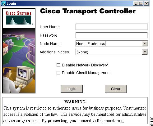
Step 3 ![]() In the Login dialog box, type a user name and password (both are case sensitive). For initial setup, type the user name "CISCO15."
In the Login dialog box, type a user name and password (both are case sensitive). For initial setup, type the user name "CISCO15."
Note ![]() The CISCO15 user is provided with every ONS 15454. CISCO15 has superuser privileges, so you can create other users. You must create another superuser before you can delete the CISCO15 user. CISCO15 is delivered without a password. To create a password for CISCO15, click the Provisioning > Security tabs after you log in and change the password. To set up ONS 15454 users and assign security, go to the "NTP-A30 Create Users and Assign Security" procedure on page 4-4. Additional information is provided in the Cisco ONS 15454 Reference Guide.
The CISCO15 user is provided with every ONS 15454. CISCO15 has superuser privileges, so you can create other users. You must create another superuser before you can delete the CISCO15 user. CISCO15 is delivered without a password. To create a password for CISCO15, click the Provisioning > Security tabs after you log in and change the password. To set up ONS 15454 users and assign security, go to the "NTP-A30 Create Users and Assign Security" procedure on page 4-4. Additional information is provided in the Cisco ONS 15454 Reference Guide.
Step 4 ![]() Each time you log into an ONS 15454, you can make selections on the following login options:
Each time you log into an ONS 15454, you can make selections on the following login options:
•![]() Node Name—Displays the IP address entered in the web browser and a pull-down menu of previously entered ONS 15454 IP addresses. You can select any ONS 15454 on the list for the login, or you can enter the IP address (or node name) of any new node where you want to log in.
Node Name—Displays the IP address entered in the web browser and a pull-down menu of previously entered ONS 15454 IP addresses. You can select any ONS 15454 on the list for the login, or you can enter the IP address (or node name) of any new node where you want to log in.
•![]() Additional Nodes—Displays a list of login node groups that are created. To create a login node group or add additional groups, see the "DLP-A61 Create Login Node Groups" task.)
Additional Nodes—Displays a list of login node groups that are created. To create a login node group or add additional groups, see the "DLP-A61 Create Login Node Groups" task.)
Note ![]() Topology hosts that were created in previous ONS 15454 releases by modifying the ctc.ini (Windows) or .ctcrc (UNIX) files are displayed as a Topology Host group under Additional Nodes.
Topology hosts that were created in previous ONS 15454 releases by modifying the ctc.ini (Windows) or .ctcrc (UNIX) files are displayed as a Topology Host group under Additional Nodes.
•![]() Disable Network Discovery—Check this box to view only the ONS 15454 (and login node group members, if any) entered in the Node Name field. Nodes linked to the node name "ONS 15454" through the DCC are not displayed. Using this option can decrease the CTC startup time in networks with many DCC-connected nodes.
Disable Network Discovery—Check this box to view only the ONS 15454 (and login node group members, if any) entered in the Node Name field. Nodes linked to the node name "ONS 15454" through the DCC are not displayed. Using this option can decrease the CTC startup time in networks with many DCC-connected nodes.
•![]() Disable Circuit Management—Check this box to disable discovery of existing circuits. Using this option can decrease the CTC initialization time in networks with many existing circuits. This option does not prevent the creation and management of new circuits.
Disable Circuit Management—Check this box to disable discovery of existing circuits. Using this option can decrease the CTC initialization time in networks with many existing circuits. This option does not prevent the creation and management of new circuits.
Step 5 ![]() Click Login.
Click Login.
If login is successful, the CTC window appears. From here, you can navigate to other CTC views to provision and manage the ONS 15454. If you need to perform the initial shelf turn up, see Chapter 4, "Turn Up Node." If login problems occur, refer to the Cisco ONS 15454 Troubleshooting Guide.
Step 6 ![]() Return to your originating procedure (NTP).
Return to your originating procedure (NTP).
DLP-A61 Create Login Node Groups
Purpose |
This task creates a login node group to display ONS 15454s that have an IP connection but not a DCC connection to the login node. |
Tools/Equipment |
None |
Prerequisite Procedures |
22 Set Up CTC Computer to Connect to the ONS 15454 |
Required/As Needed |
As needed |
Onsite/Remote |
Onsite or remote |
Security Level |
Provisioning or higher |
Step 1 ![]() From the Edit menu, choose Preferences.
From the Edit menu, choose Preferences.
Step 2 ![]() Click Login Node Group and Create Group.
Click Login Node Group and Create Group.
Step 3 ![]() Enter a name for the group in the Create Login Group Name dialog box. Click OK.
Enter a name for the group in the Create Login Group Name dialog box. Click OK.
Step 4 ![]() Under Members, type the IP address (or node name) of a node you want to add to the group. Click Add. Repeat this step for each node you want to add to the group.
Under Members, type the IP address (or node name) of a node you want to add to the group. Click Add. Repeat this step for each node you want to add to the group.
Step 5 ![]() Click OK.
Click OK.
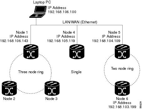
The next time you log into an ONS 15454, the login node group will be available in the Additional Nodes list of the Login dialog box. For example, in Figure 3-3, a login node group, "Test Group," is created that contains the IP addresses for Nodes 1, 4, and 5. During login, if you select the Test Group group under Additional Nodes and Disable Network Discovery is not selected, all nodes in the figure are displayed. If Test Group and Disable Network Discovery are both selected, Nodes 1, 4, and 5 are displayed. You can create as many login groups as you need. The groups are stored in the CTC preferences file and are not visible to other users.
Figure 3-3 Login Node Group
Step 6 ![]() Return to your originating procedure (NTP).
Return to your originating procedure (NTP).
DLP-A62 Add a Node to the Current Session or Login Group
Step 1 ![]() Log into an ONS 15454 on the network. See the "DLP-A60 Log into CTC" task for instructions. If you are already logged in, go to Step 2.
Log into an ONS 15454 on the network. See the "DLP-A60 Log into CTC" task for instructions. If you are already logged in, go to Step 2.
Step 2 ![]() From the CTC File menu, click Add Node (or click the Add Node button on the toolbar).
From the CTC File menu, click Add Node (or click the Add Node button on the toolbar).
Step 3 ![]() In the Add Node dialog box, enter the node name (or IP address).
In the Add Node dialog box, enter the node name (or IP address).
Step 4 ![]() If you want to add the node to the current login group, click Add Node to Current Login Group. Otherwise, leave it unchecked.
If you want to add the node to the current login group, click Add Node to Current Login Group. Otherwise, leave it unchecked.
Note ![]() The Add Node to Current Login Group check box is active only if you selected a login group when you logged into CTC.
The Add Node to Current Login Group check box is active only if you selected a login group when you logged into CTC.
Step 5 ![]() Click OK.
Click OK.
After a few seconds, the new node is displayed on the network view map.
Step 6 ![]() Return to your originating procedure (NTP).
Return to your originating procedure (NTP).
 Feedback