- About this Guide
- Chapter 1, Install the Shelf and Backplane Cable
- Chapter 2, Install Cards and Fiber-Optic Cable
- Chapter 3, Connect the PC and Log Into the GUI
- Chapter 4, Turn Up Node
- Chapter 5, Turn Up Network
- Chapter 6, Create Circuits and VT Tunnels
- Chapter 7, Manage Alarms
- Chapter 8, Monitor Performance
- Chapter 9, Manage Circuits
- Chapter 10, Change Node Settings
- Chapter 11, Change Card Settings
- Chapter 12, Upgrade Cards and Spans
- Chapter 13, Upgrade Network Configurations
- Chapter 14, Add and Remove Nodes
- Chapter 15, Maintain the Node
- Chapter 16, Power Down the ONS 15454
- Appendix A, CTC Information and Shortcuts
- Appendix B, Shelf Assembly Specifications
- Appendix C, Network Element Defaults
- Glossary
Cisco ONS 15454 Procedure Guide, Release 4.0
Bias-Free Language
The documentation set for this product strives to use bias-free language. For the purposes of this documentation set, bias-free is defined as language that does not imply discrimination based on age, disability, gender, racial identity, ethnic identity, sexual orientation, socioeconomic status, and intersectionality. Exceptions may be present in the documentation due to language that is hardcoded in the user interfaces of the product software, language used based on RFP documentation, or language that is used by a referenced third-party product. Learn more about how Cisco is using Inclusive Language.
- Updated:
- March 20, 2015
Chapter: Chapter 10, Change Node Settings
- Before You Begin
- NTP-A81 Change Node Management Information
- NTP-A201 Change CTC Network Access
- NTP-A202 Customize the CTC Network View
- NTP-A203 Modify or Delete Card Protection Settings
- NTP-A204 Delete a SONET DCC Termination
- NTP-A85 Change Node Timing
- NTP-A205 Modify Users and Change Security
- DLP-A271 Change Security Policy - Single Node
- DLP-A272 Change Security Policy - Multiple Nodes
- DLP-A158 Change User Password and Security Level - Single Node
- DLP-A160 Change User Password and Security Level - Multiple Nodes
- DLP-A315 Log Out a User - Single Node
- DLP-A316 Log Out a User - Multiple Nodes
- DLP-A159 Delete User - Single Node
- DLP-A161 Delete User - Multiple Nodes
- NTP-A87 Change SNMP Settings
Change Node Settings

Note ![]() The terms "Unidirectional Path Switched Ring" and "UPSR" may appear in Cisco literature. These terms do not refer to using Cisco ONS 15xxx products in a unidirectional path switched ring configuration. Rather, these terms, as well as "Path Protected Mesh Network" and "PPMN," refer generally to Cisco's path protection feature, which may be used in any topological network configuration. Cisco does not recommend using its path protection feature in any particular topological network configuration.
The terms "Unidirectional Path Switched Ring" and "UPSR" may appear in Cisco literature. These terms do not refer to using Cisco ONS 15xxx products in a unidirectional path switched ring configuration. Rather, these terms, as well as "Path Protected Mesh Network" and "PPMN," refer generally to Cisco's path protection feature, which may be used in any topological network configuration. Cisco does not recommend using its path protection feature in any particular topological network configuration.
This chapter explains how to modify node provisioning for the Cisco ONS 15454. To provision a new node, see Chapter 4, "Turn Up Node." To change default network element settings and to view a list of those settings, see Appendix C, "Network Element Defaults."
Before You Begin
Before performing the following procedures, investigate all alarms and clear any trouble conditions. Refer to the Cisco ONS 15454 Troubleshooting Guide as necessary.
This section lists the chapter procedures (NTPs). Turn to a procedure for applicable tasks (DLPs).
1. ![]() 81 Change Node Management Information—As needed, complete this procedure to change node name, contact information, latitude, longitude, date, and time.
81 Change Node Management Information—As needed, complete this procedure to change node name, contact information, latitude, longitude, date, and time.
2. ![]() 201 Change CTC Network Access—As needed, complete these procedures to change the IP address, default router, subnet mask, network configuration settings, and static routes.
201 Change CTC Network Access—As needed, complete these procedures to change the IP address, default router, subnet mask, network configuration settings, and static routes.
3. ![]() 202 Customize the CTC Network View—As needed, complete this procedure to create domains and customize the appearance of the network map, including specifying a different default map, creating domains, selecting your own map or image, changing the background color.
202 Customize the CTC Network View—As needed, complete this procedure to create domains and customize the appearance of the network map, including specifying a different default map, creating domains, selecting your own map or image, changing the background color.
4. ![]() 203 Modify or Delete Card Protection Settings—As needed, complete this procedure to modify and delete 1:1, 1:N, 1+1, and Y Cable protection groups.
203 Modify or Delete Card Protection Settings—As needed, complete this procedure to modify and delete 1:1, 1:N, 1+1, and Y Cable protection groups.
5. ![]() 85 Change Node Timing—As needed, complete this procedure to make changes to the network timing parameters.
85 Change Node Timing—As needed, complete this procedure to make changes to the network timing parameters.
6. ![]() A205 Modify Users and Change Security—As needed, complete this procedure to make changes to user settings, including security level and security policies, and to delete users.
A205 Modify Users and Change Security—As needed, complete this procedure to make changes to user settings, including security level and security policies, and to delete users.
7. ![]() 87 Change SNMP Settings—As needed, complete this procedure to modify or delete SNMP.
87 Change SNMP Settings—As needed, complete this procedure to modify or delete SNMP.
NTP-A81 Change Node Management Information
Step 1 ![]() Log into the ONS 15454 node where you want to change the settings. See the "DLP-A60 Log into CTC" task on page 3-23. If you are already logged in, continue with Step 2.
Log into the ONS 15454 node where you want to change the settings. See the "DLP-A60 Log into CTC" task on page 3-23. If you are already logged in, continue with Step 2.
Step 2 ![]() Complete the "NTP-A108 Back Up the Database" procedure on page 15-8.
Complete the "NTP-A108 Back Up the Database" procedure on page 15-8.
Step 3 ![]() Click the Provisioning > General tabs.
Click the Provisioning > General tabs.
Step 4 ![]() Complete the "DLP-A140 Change the Node Name, Date, Time, and Contact Information" task.
Complete the "DLP-A140 Change the Node Name, Date, Time, and Contact Information" task.
Step 5 ![]() Complete the "DLP-A265 Change the Login Legal Disclaimer" task if needed.
Complete the "DLP-A265 Change the Login Legal Disclaimer" task if needed.
Step 6 ![]() After confirming the changes, complete the "NTP-A108 Back Up the Database" procedure on page 15-8.
After confirming the changes, complete the "NTP-A108 Back Up the Database" procedure on page 15-8.
Stop. You have completed this procedure.
DLP-A140 Change the Node Name, Date, Time, and Contact Information
Note ![]() Changing the date, time, or time zone may invalidate the node's performance monitoring counters.
Changing the date, time, or time zone may invalidate the node's performance monitoring counters.
Step 1 ![]() In node view, click the Provisioning > General tabs.
In node view, click the Provisioning > General tabs.
Step 2 ![]() Change any of the following:
Change any of the following:
•![]() General: Node Name
General: Node Name
•![]() General: Contact
General: Contact
•![]() Location: Latitude
Location: Latitude
•![]() Location: Longitude
Location: Longitude
•![]() Location: Description
Location: Description
Note ![]() To see changes to longitude or latitude on the network map, you must go to network view and right-click the specified node, then click Reset Node Position.
To see changes to longitude or latitude on the network map, you must go to network view and right-click the specified node, then click Reset Node Position.
•![]() Time: Use SNTP Server
Time: Use SNTP Server
•![]() Time: Date (M/D/Y)
Time: Date (M/D/Y)
•![]() Time: Time (H:M:S)
Time: Time (H:M:S)
•![]() Time: Time Zone
Time: Time Zone
•![]() Time: Use Daylight Saving Time
Time: Use Daylight Saving Time
See the "NTP-A25 Set Up Name, Date, Time, and Contact Information" procedure on page 4-6 for detailed field descriptions.
Step 3 ![]() Click Apply. Confirm that the changes appear; if not, repeat the task.
Click Apply. Confirm that the changes appear; if not, repeat the task.
Step 4 ![]() Return to the "81 Change Node Management Information" procedure.
Return to the "81 Change Node Management Information" procedure.
DLP-A265 Change the Login Legal Disclaimer
Step 1 ![]() In node view, click the Provisioning > Security > Legal Disclaimer > HTML tabs.
In node view, click the Provisioning > Security > Legal Disclaimer > HTML tabs.
Step 2 ![]() The existing statement is a default, non-customer-specific disclaimer. If you want to edit this statement with specifics for your company, you can change the text. You can also use the following HTML commands to format the text:
The existing statement is a default, non-customer-specific disclaimer. If you want to edit this statement with specifics for your company, you can change the text. You can also use the following HTML commands to format the text:
•![]() <b> Begins boldface font
<b> Begins boldface font
•![]() </b> Ends boldface font
</b> Ends boldface font
•![]() <center> Aligns type in the center of the window
<center> Aligns type in the center of the window
•![]() </center> Ends the center alignment
</center> Ends the center alignment
•![]() <font=n, where n = point size> Changes the font to the new size
<font=n, where n = point size> Changes the font to the new size
•![]() </font> Ends the font size command
</font> Ends the font size command
•![]() <p> Creates a line break
<p> Creates a line break
•![]() <sub> Begins subscript
<sub> Begins subscript
•![]() </sub> Ends subscript
</sub> Ends subscript
•![]() <sup> Begins superscript
<sup> Begins superscript
•![]() </sup> Ends superscript
</sup> Ends superscript
•![]() <u> Starts underline
<u> Starts underline
•![]() </u> Ends underline
</u> Ends underline
Step 3 ![]() If you want to preview your changed statement and formatting, click the Preview subtab.
If you want to preview your changed statement and formatting, click the Preview subtab.
Step 4 ![]() Click Apply.
Click Apply.
Step 5 ![]() Return to the "81 Change Node Management Information" procedure.
Return to the "81 Change Node Management Information" procedure.
NTP-A201 Change CTC Network Access
Note ![]() Additional ONS 15454 networking information and procedures, including IP addressing examples, static route scenarios, Open Shortest Path First (OSPF) protocol, and routing information protocol options are provided in the IP Networking section of the Cisco ONS 15454 Reference Manual.
Additional ONS 15454 networking information and procedures, including IP addressing examples, static route scenarios, Open Shortest Path First (OSPF) protocol, and routing information protocol options are provided in the IP Networking section of the Cisco ONS 15454 Reference Manual.
Step 1 ![]() Log into the ONS 15454 node where you want to change the settings. See the "DLP-A60 Log into CTC" task on page 3-23. If you are already logged in, continue with Step 2.
Log into the ONS 15454 node where you want to change the settings. See the "DLP-A60 Log into CTC" task on page 3-23. If you are already logged in, continue with Step 2.
Step 2 ![]() Complete the "NTP-A108 Back Up the Database" procedure on page 15-8.
Complete the "NTP-A108 Back Up the Database" procedure on page 15-8.
Step 3 ![]() Perform any of the following tasks as needed:
Perform any of the following tasks as needed:
•![]() DLP-A250 Set Up or Change Open Shortest Path First Protocol, page 4-15.
DLP-A250 Set Up or Change Open Shortest Path First Protocol, page 4-15.
Step 4 ![]() Complete the "NTP-A108 Back Up the Database" procedure on page 15-8.
Complete the "NTP-A108 Back Up the Database" procedure on page 15-8.
Stop. You have completed this procedure.
DLP-A266 Change IP Settings
Step 1 ![]() In node view, click the Provisioning > Network > General tabs.
In node view, click the Provisioning > Network > General tabs.
Step 2 ![]() Change any of the following:
Change any of the following:
•![]() IP Address
IP Address
•![]() Suppress CTC IP Display
Suppress CTC IP Display
•![]() LCD IP Setting
LCD IP Setting
•![]() Default Router
Default Router
•![]() Subnet Mask Length
Subnet Mask Length
•![]() Forward DHCP Request To
Forward DHCP Request To
•![]() TCC CORBA (IIOP) Listener Port
TCC CORBA (IIOP) Listener Port
•![]() Gateway Settings
Gateway Settings
See the "DLP-A249 Provision IP Settings" task on page 4-9 for detailed field descriptions.
Step 3 ![]() Click Apply.
Click Apply.
If you changed any network fields that will cause the node to reboot, the Change Network Configuration confirmation dialog box appears. If you changed a Gateway Setting, a confirmation appropriate to the gateway field appears.
Step 4 ![]() If a confirmation dialog box appears, click Yes.
If a confirmation dialog box appears, click Yes.
If you changed an IP address, subnet mask length, or TCC CORBA (IIOP) Listener Port, both ONS 15454 TCC+/TCC2 cards will reboot, one at a time. A TCC+/TCC2 reboot causes a temporary loss of connectivity to the node, but traffic is unaffected.
Step 5 ![]() Confirm that the changes appear on the Provisioning > Network > General tab. If the changes do not appear, repeat the task. Refer to the Cisco ONS 15454 Troubleshooting Guide.
Confirm that the changes appear on the Provisioning > Network > General tab. If the changes do not appear, repeat the task. Refer to the Cisco ONS 15454 Troubleshooting Guide.
Step 6 ![]() Return to your originating procedure (NTP).
Return to your originating procedure (NTP).
DLP-A142 Modify a Static Route
Step 1 ![]() In node view, click the Provisioning > Network tabs.
In node view, click the Provisioning > Network tabs.
Step 2 ![]() Click the Static Routing tab.
Click the Static Routing tab.
Step 3 ![]() Click the static route you want to edit.
Click the static route you want to edit.
Step 4 ![]() Click Edit.
Click Edit.
Step 5 ![]() In the Edit Selected Static Route dialog box, enter the following (see the "DLP-A65 Create a Static Route" task on page 4-14 for detailed field descriptions):
In the Edit Selected Static Route dialog box, enter the following (see the "DLP-A65 Create a Static Route" task on page 4-14 for detailed field descriptions):
•![]() Mask
Mask
•![]() Next Hop
Next Hop
•![]() Cost
Cost
Step 6 ![]() Click OK.
Click OK.
Step 7 ![]() Return to your originating procedure (NTP).
Return to your originating procedure (NTP).
DLP-A143 Delete a Static Route
Step 1 ![]() In node view, click the Provisioning > Network > Static Routing tabs.
In node view, click the Provisioning > Network > Static Routing tabs.
Step 2 ![]() Click the static route you want to delete.
Click the static route you want to delete.
Step 3 ![]() Click Delete. A confirmation dialog box appears.
Click Delete. A confirmation dialog box appears.
Step 4 ![]() Click Yes.
Click Yes.
Step 5 ![]() Return to your originating procedure (NTP).
Return to your originating procedure (NTP).
DLP-A144 Disable OSPF
Step 1 ![]() In node view, click the Provisioning > Network > OSPF tabs (Figure 10-1). The OSPF subtab has several options.
In node view, click the Provisioning > Network > OSPF tabs (Figure 10-1). The OSPF subtab has several options.
Figure 10-1 Disabling OSPF on the ONS 15454
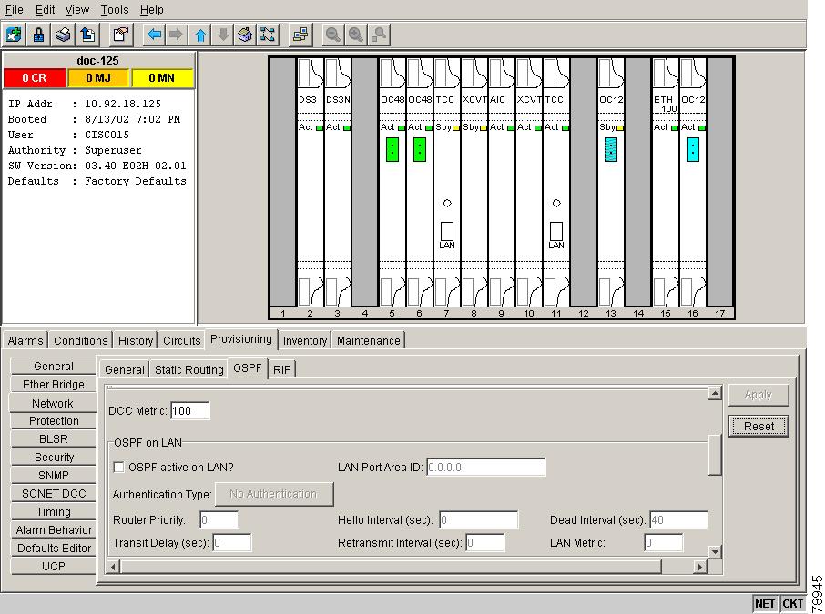
Step 2 ![]() In the OSPF on LAN area, uncheck the OSPF active on LAN check box.
In the OSPF on LAN area, uncheck the OSPF active on LAN check box.
Step 3 ![]() Click Apply. Confirm that the changes appear; if not, repeat the task.
Click Apply. Confirm that the changes appear; if not, repeat the task.
Step 4 ![]() Return to your originating procedure (NTP).
Return to your originating procedure (NTP).
NTP-A202 Customize the CTC Network View
Step 1 ![]() Log into an ONS 15454. See the "DLP-A60 Log into CTC" task on page 3-23 for instructions.
Log into an ONS 15454. See the "DLP-A60 Log into CTC" task on page 3-23 for instructions.
Step 2 ![]() Complete the following tasks, as needed:
Complete the following tasks, as needed:
•![]() 145 Change the Network View Background Color
145 Change the Network View Background Color
•![]() 267 Change the Default Network View Background Map
267 Change the Default Network View Background Map
•![]() 268 Apply a Custom Network View Background Map
268 Apply a Custom Network View Background Map
•![]() 269 Enable Dialog Box Do-Not-Display Option
269 Enable Dialog Box Do-Not-Display Option
Stop. You have completed this procedure.
DLP-A145 Change the Network View Background Color
Note ![]() If you modify background colors, the change is stored in your CTC user profile on the computer. The change does not affect other CTC users.
If you modify background colors, the change is stored in your CTC user profile on the computer. The change does not affect other CTC users.
Step 1 ![]() From the View menu choose Go to Network View.
From the View menu choose Go to Network View.
Step 2 ![]() Right-click the network view or domain map area and choose Set Background Color from the shortcut menu.
Right-click the network view or domain map area and choose Set Background Color from the shortcut menu.
Step 3 ![]() On the Choose Color dialog box, select a background color.
On the Choose Color dialog box, select a background color.
Step 4 ![]() Click OK.
Click OK.
Step 5 ![]() Return to your originating procedure (NTP).
Return to your originating procedure (NTP).
DLP-A267 Change the Default Network View Background Map
Note ![]() If you modify the background image, the change is stored in your CTC user profile on the computer. The change does not affect other CTC users.
If you modify the background image, the change is stored in your CTC user profile on the computer. The change does not affect other CTC users.
Step 1 ![]() From the View menu choose Go to Network View.
From the View menu choose Go to Network View.
Step 2 ![]() From the Edit menu, choose Preferences.
From the Edit menu, choose Preferences.
Step 3 ![]() On the Preferences dialog box, click the Map tab, then check the Use Default Map check box if it is not already selected.
On the Preferences dialog box, click the Map tab, then check the Use Default Map check box if it is not already selected.
Step 4 ![]() Click the Default Maps field and choose a default map from the pull-down menu. Map choices are: Germany, Japan, Netherlands, South Korea, United Kingdom, and the United States (default).
Click the Default Maps field and choose a default map from the pull-down menu. Map choices are: Germany, Japan, Netherlands, South Korea, United Kingdom, and the United States (default).
Step 5 ![]() Click Apply. The new network map is displayed.
Click Apply. The new network map is displayed.
Step 6 ![]() Click OK.
Click OK.
Step 7 ![]() If the ONS 15454 icons are not visible, right-click the network view and choose Zoom Out. Repeat until all the ONS 15454 icons are visible.
If the ONS 15454 icons are not visible, right-click the network view and choose Zoom Out. Repeat until all the ONS 15454 icons are visible.
Step 8 ![]() If you need to reposition the node icons, drag and drop them one at a time to a new location on the map.
If you need to reposition the node icons, drag and drop them one at a time to a new location on the map.
Step 9 ![]() If you want to change the magnification of the icons, right-click the network view and choose Zoom In. Repeat until the ONS 15454 icons are displayed at the magnification you want.
If you want to change the magnification of the icons, right-click the network view and choose Zoom In. Repeat until the ONS 15454 icons are displayed at the magnification you want.
Step 10 ![]() Return to your originating procedure (NTP).
Return to your originating procedure (NTP).
DLP-A268 Apply a Custom Network View Background Map
Note ![]() You can replace the network view background image with any JPEG or GIF image that is accessible on a local or network drive. If you apply a custom background image, the change is stored in your CTC user profile on the computer. The change does not affect other CTC users.
You can replace the network view background image with any JPEG or GIF image that is accessible on a local or network drive. If you apply a custom background image, the change is stored in your CTC user profile on the computer. The change does not affect other CTC users.
Step 1 ![]() From the View menu choose Go to Network View.
From the View menu choose Go to Network View.
Step 2 ![]() Right-click the network or domain map and select Set Background Image.
Right-click the network or domain map and select Set Background Image.
Step 3 ![]() Click Browse. Navigate to the graphic file you want to use as a background.
Click Browse. Navigate to the graphic file you want to use as a background.
Step 4 ![]() Select the file. Click Open.
Select the file. Click Open.
Step 5 ![]() Click Apply and then click OK.
Click Apply and then click OK.
Step 6 ![]() If the ONS 15454 icons are not visible, right-click the network view and choose Zoom Out. Repeat this step until all the ONS 15454 icons are visible.
If the ONS 15454 icons are not visible, right-click the network view and choose Zoom Out. Repeat this step until all the ONS 15454 icons are visible.
Step 7 ![]() If you need to reposition the node icons, drag and drop them one at a time to a new location on the map.
If you need to reposition the node icons, drag and drop them one at a time to a new location on the map.
Step 8 ![]() If you want to change the magnification of the icons, right-click the network view and choose Zoom In. Repeat until the ONS 15454 icons are displayed at the magnification you want.
If you want to change the magnification of the icons, right-click the network view and choose Zoom In. Repeat until the ONS 15454 icons are displayed at the magnification you want.
Step 9 ![]() At the network view, use the CTC toolbar Zoom buttons (or right-click the graphic area and select a Zoom command from the shortcut menu) to set the area of the image you want to view.
At the network view, use the CTC toolbar Zoom buttons (or right-click the graphic area and select a Zoom command from the shortcut menu) to set the area of the image you want to view.
Step 10 ![]() Return to your originating procedure (NTP).
Return to your originating procedure (NTP).
DLP-A148 Create Domain Icons
Note ![]() Domains that you create are visible to all users who log into the network.
Domains that you create are visible to all users who log into the network.
Step 1 ![]() From the View menu choose Go to Network View.
From the View menu choose Go to Network View.
Step 2 ![]() Right-click the network map and choose Create New Domain from the shortcut menu.
Right-click the network map and choose Create New Domain from the shortcut menu.
Step 3 ![]() When the domain icon appears on the map, click the map name and type the domain name.
When the domain icon appears on the map, click the map name and type the domain name.
Step 4 ![]() Press Enter.
Press Enter.
Step 5 ![]() Return to your originating procedure (NTP).
Return to your originating procedure (NTP).
DLP-A149 Manage Domain Icons
Purpose |
Use this task to manage CTC network view domain icons. |
Tools/Equipment |
None |
Prerequisite procedures |
DLP-A60 Log into CTC, page 3-23 |
Required/As needed |
As needed |
Onsite/Remote |
Onsite or remote |
Security Level |
Provisioning or higher |
Note ![]() All domain changes, such as added or removed nodes, are visible to all users who log into the network.
All domain changes, such as added or removed nodes, are visible to all users who log into the network.
Step 1 ![]() From the View menu choose Go to Network View.
From the View menu choose Go to Network View.
Step 2 ![]() Locate the domain action you want in Table 10-1 and complete the appropriate steps.
Locate the domain action you want in Table 10-1 and complete the appropriate steps.
Step 3 ![]() Return to your originating procedure (NTP).
Return to your originating procedure (NTP).
DLP-A269 Enable Dialog Box Do-Not-Display Option
Note ![]() If any user who has rights to perform an operation (for example, creating a circuit) selects the "Do not show this dialog again" check box on a dialog box, the dialog box is not displayed for any other users who perform that operation on the network unless the command is overridden using the following task.
If any user who has rights to perform an operation (for example, creating a circuit) selects the "Do not show this dialog again" check box on a dialog box, the dialog box is not displayed for any other users who perform that operation on the network unless the command is overridden using the following task.
Step 1 ![]() From the Edit menu, choose Preferences.
From the Edit menu, choose Preferences.
Step 2 ![]() In the Preferences dialog box, click the General tab.
In the Preferences dialog box, click the General tab.
The Preferences Management area field lists all dialog boxes where "Do not show this dialog again." was checked.
Step 3 ![]() Choose one of the following:
Choose one of the following:
•![]() Don't Show Any—Hides all do-not-display check boxes.
Don't Show Any—Hides all do-not-display check boxes.
•![]() Show All—Overrides do-not-display check box selections and displays all dialog boxes.
Show All—Overrides do-not-display check box selections and displays all dialog boxes.
Step 4 ![]() Click OK.
Click OK.
Step 5 ![]() Return to your originating procedure (NTP).
Return to your originating procedure (NTP).
NTP-A203 Modify or Delete Card Protection Settings

Step 1 ![]() Log into the ONS 15454 node where you want to change the settings. See the "DLP-A60 Log into CTC" task on page 3-23. If you are already logged in, continue with Step 2.
Log into the ONS 15454 node where you want to change the settings. See the "DLP-A60 Log into CTC" task on page 3-23. If you are already logged in, continue with Step 2.
Step 2 ![]() Complete the "NTP-A108 Back Up the Database" procedure on page 15-8.
Complete the "NTP-A108 Back Up the Database" procedure on page 15-8.
Step 3 ![]() Perform any of the following tasks as needed:
Perform any of the following tasks as needed:
•![]() 150 Modify a 1:1 Protection Group
150 Modify a 1:1 Protection Group
•![]() 152 Modify a 1:N Protection Group
152 Modify a 1:N Protection Group
•![]() 154 Modify a 1+1 Protection Group
154 Modify a 1+1 Protection Group
•![]() 270 Modify a Y Cable Protection Group
270 Modify a Y Cable Protection Group
•![]() 155 Delete a Protection Group
155 Delete a Protection Group
Step 4 ![]() Complete the "NTP-A108 Back Up the Database" procedure on page 15-8.
Complete the "NTP-A108 Back Up the Database" procedure on page 15-8.
Stop. You have completed this procedure.
DLP-A150 Modify a 1:1 Protection Group
Step 1 ![]() In node view, click the Provisioning > Protection tabs.
In node view, click the Provisioning > Protection tabs.
Step 2 ![]() Under Protection Groups, click the 1:1 protection group you want to modify.
Under Protection Groups, click the 1:1 protection group you want to modify.
Step 3 ![]() Under Selected Group, you can modify the following, as needed:
Under Selected Group, you can modify the following, as needed:
•![]() Name—As needed, type the changes to the protection group name. The name can have up to 32 alphanumeric characters.
Name—As needed, type the changes to the protection group name. The name can have up to 32 alphanumeric characters.
•![]() Revertive—Check this box if you want traffic to revert to the working card after failure conditions stay corrected for the amount of time chosen from the Reversion Time menu. Uncheck if you do not want traffic to revert.
Revertive—Check this box if you want traffic to revert to the working card after failure conditions stay corrected for the amount of time chosen from the Reversion Time menu. Uncheck if you do not want traffic to revert.
•![]() Reversion time—If the Revertive check box is selected, choose the reversion time from the Reversion time pull-down menu. The range is 0.5 to 12.0 minutes. The default is 5.0 minutes. This is the amount of time that will elapse before the traffic reverts to the working card. Traffic can revert when conditions causing the switch are cleared.
Reversion time—If the Revertive check box is selected, choose the reversion time from the Reversion time pull-down menu. The range is 0.5 to 12.0 minutes. The default is 5.0 minutes. This is the amount of time that will elapse before the traffic reverts to the working card. Traffic can revert when conditions causing the switch are cleared.
Step 4 ![]() Click Apply. Confirm that the changes appear.
Click Apply. Confirm that the changes appear.
Note ![]() If the changes do not appear, repeat the task. Refer to the Cisco ONS 15454 Troubleshooting Guide.
If the changes do not appear, repeat the task. Refer to the Cisco ONS 15454 Troubleshooting Guide.
Step 5 ![]() Return to your originating procedure (NTP).
Return to your originating procedure (NTP).
Note ![]() To convert electrical protection groups, see the "NTP-A91 Upgrade DS-1 and DS-3 Protect Cards from 1:1 Protection to 1:N Protection" procedure on page 11-53.
To convert electrical protection groups, see the "NTP-A91 Upgrade DS-1 and DS-3 Protect Cards from 1:1 Protection to 1:N Protection" procedure on page 11-53.
DLP-A152 Modify a 1:N Protection Group
Step 1 ![]() Verify that the DS-1 and DS-3 cards are installed according to the 1:N specifications in the "DLP-A72 Create a 1:N Protection Group" task on page 4-28.
Verify that the DS-1 and DS-3 cards are installed according to the 1:N specifications in the "DLP-A72 Create a 1:N Protection Group" task on page 4-28.
Step 2 ![]() In node view, click the Provisioning > Protection tabs.
In node view, click the Provisioning > Protection tabs.
Step 3 ![]() Under Protection Groups, click the 1:N protection group you want to modify.
Under Protection Groups, click the 1:N protection group you want to modify.
Step 4 ![]() Under Selected Group, change any of the following, as needed:
Under Selected Group, change any of the following, as needed:
•![]() Name—As needed, type the changes to the protection group name. The name can have up to 32 alphanumeric characters.
Name—As needed, type the changes to the protection group name. The name can have up to 32 alphanumeric characters.
•![]() Available Cards—If cards are available, they will appear here. Use the arrow buttons to move them into the Working Cards column.
Available Cards—If cards are available, they will appear here. Use the arrow buttons to move them into the Working Cards column.
•![]() Working Cards—Use the arrow buttons to move cards out of the Working Cards column.
Working Cards—Use the arrow buttons to move cards out of the Working Cards column.
•![]() Reversion Time—Choose a reversion time from the pull-down menu. The range is 0.5 to 12.0 minutes. The default is 5.0 minutes. This is the amount of time that will elapse before the traffic reverts to the working card. Traffic can revert when conditions causing the switch are cleared.
Reversion Time—Choose a reversion time from the pull-down menu. The range is 0.5 to 12.0 minutes. The default is 5.0 minutes. This is the amount of time that will elapse before the traffic reverts to the working card. Traffic can revert when conditions causing the switch are cleared.
See the "DLP-A72 Create a 1:N Protection Group" task on page 4-28 for field descriptions.
Step 5 ![]() Click Apply. The changes are applied. Confirm that the changes appear.
Click Apply. The changes are applied. Confirm that the changes appear.
Note ![]() If the changes do not appear, repeat the task. Refer to the Cisco ONS 15454 Troubleshooting Guide.
If the changes do not appear, repeat the task. Refer to the Cisco ONS 15454 Troubleshooting Guide.
Step 6 ![]() Return to your originating procedure (NTP).
Return to your originating procedure (NTP).
Note ![]() To convert electrical protection groups, see the "NTP-A91 Upgrade DS-1 and DS-3 Protect Cards from 1:1 Protection to 1:N Protection" procedure on page 11-53.
To convert electrical protection groups, see the "NTP-A91 Upgrade DS-1 and DS-3 Protect Cards from 1:1 Protection to 1:N Protection" procedure on page 11-53.
DLP-A154 Modify a 1+1 Protection Group
Step 1 ![]() In node view, click the Provisioning > Protection tabs.
In node view, click the Provisioning > Protection tabs.
Step 2 ![]() Under Protection Groups, click the 1+1 protection group you want to modify.
Under Protection Groups, click the 1+1 protection group you want to modify.
Step 3 ![]() Under Selected Group, you can modify the following:
Under Selected Group, you can modify the following:
•![]() Name—As needed, type the changes to the protection group name. The name can have up to 32 alphanumeric characters.
Name—As needed, type the changes to the protection group name. The name can have up to 32 alphanumeric characters.
•![]() Bidirectional switching—As needed, check or uncheck
Bidirectional switching—As needed, check or uncheck
•![]() Revertive—Check this box if you want traffic to revert to the working card after failure conditions stay corrected for the amount of time chosen from the Reversion Time menu. Uncheck if you do not want traffic to revert.
Revertive—Check this box if you want traffic to revert to the working card after failure conditions stay corrected for the amount of time chosen from the Reversion Time menu. Uncheck if you do not want traffic to revert.
•![]() Reversion time—If the Revertive check box is selected, choose the reversion time from the Reversion time pull-down menu. The range is 0.5 to 12.0 minutes. The default is 5.0 minutes. This is the amount of time that will elapse before the traffic reverts to the working card. Traffic can revert when conditions causing the switch are cleared.
Reversion time—If the Revertive check box is selected, choose the reversion time from the Reversion time pull-down menu. The range is 0.5 to 12.0 minutes. The default is 5.0 minutes. This is the amount of time that will elapse before the traffic reverts to the working card. Traffic can revert when conditions causing the switch are cleared.
See the "DLP-A73 Create a 1+1 Protection Group" task on page 4-29 for field descriptions.
Step 4 ![]() Click Apply. Confirm that the changes appear.
Click Apply. Confirm that the changes appear.
Note ![]() If the changes do not appear, repeat the task. Refer to the Cisco ONS 15454 Troubleshooting Guide.
If the changes do not appear, repeat the task. Refer to the Cisco ONS 15454 Troubleshooting Guide.
Step 5 ![]() Return to your originating procedure (NTP).
Return to your originating procedure (NTP).
DLP-A270 Modify a Y Cable Protection Group
Step 1 ![]() In node view, click the Provisioning > Protection tabs.
In node view, click the Provisioning > Protection tabs.
Step 2 ![]() Under Protection Groups, click the Y Cable protection group you want to modify.
Under Protection Groups, click the Y Cable protection group you want to modify.
Step 3 ![]() Under Selected Group, you can modify the following:
Under Selected Group, you can modify the following:
•![]() Name—As needed, type the changes to the protection group name. The name can have up to 32 alphanumeric characters.
Name—As needed, type the changes to the protection group name. The name can have up to 32 alphanumeric characters.
•![]() Revertive—Check this box if you want traffic to revert to the working card after failure conditions stay corrected for the amount of time chosen from the Reversion Time menu. Uncheck if you do not want traffic to revert.
Revertive—Check this box if you want traffic to revert to the working card after failure conditions stay corrected for the amount of time chosen from the Reversion Time menu. Uncheck if you do not want traffic to revert.
•![]() Reversion time—If the Revertive check box is selected, choose the reversion time from the Reversion time pull-down menu. The range is 0.5 to 12.0 minutes. The default is 5.0 minutes. This is the amount of time that will elapse before the traffic reverts to the working card. Traffic can revert when conditions causing the switch are cleared.
Reversion time—If the Revertive check box is selected, choose the reversion time from the Reversion time pull-down menu. The range is 0.5 to 12.0 minutes. The default is 5.0 minutes. This is the amount of time that will elapse before the traffic reverts to the working card. Traffic can revert when conditions causing the switch are cleared.
See the "DLP-A252 Create a Y Cable Protection Group" task on page 4-31 for field descriptions.
Step 4 ![]() Click Apply. Confirm that the changes appear.
Click Apply. Confirm that the changes appear.
Note ![]() If the changes do not appear, repeat the task. Refer to the Cisco ONS 15454 Troubleshooting Guide.
If the changes do not appear, repeat the task. Refer to the Cisco ONS 15454 Troubleshooting Guide.
Step 5 ![]() Return to your originating procedure (NTP).
Return to your originating procedure (NTP).
DLP-A155 Delete a Protection Group
Step 1 ![]() In the node view, click the Provisioning > Protection tabs.
In the node view, click the Provisioning > Protection tabs.
Step 2 ![]() Under Protection Groups, click the protection group you want to delete.
Under Protection Groups, click the protection group you want to delete.
Step 3 ![]() Click Delete.
Click Delete.
Step 4 ![]() Click Yes in the Delete Protection Group dialog box to confirm deletion. Confirm that the changes appear; if they do not, repeat Steps 1- 3.
Click Yes in the Delete Protection Group dialog box to confirm deletion. Confirm that the changes appear; if they do not, repeat Steps 1- 3.
Step 5 ![]() Return to your originating procedure (NTP).
Return to your originating procedure (NTP).
NTP-A204 Delete a SONET DCC Termination
Note ![]() Deleting a DCC termination may cause you to lose visibility of nodes that do not have other DCCs or network connections to the CTC computer.
Deleting a DCC termination may cause you to lose visibility of nodes that do not have other DCCs or network connections to the CTC computer.
Step 1 ![]() Log into the ONS 15454 node where you want to delete the DCC termination. See the "DLP-A60 Log into CTC" task on page 3-23. If you are already logged in, continue with Step 2.
Log into the ONS 15454 node where you want to delete the DCC termination. See the "DLP-A60 Log into CTC" task on page 3-23. If you are already logged in, continue with Step 2.
Step 2 ![]() In node view, click the Provisioning > DCC/GCC tabs.
In node view, click the Provisioning > DCC/GCC tabs.
Step 3 ![]() Click the DCC termination to be deleted and click Delete. The Delete SDCC Termination dialog box opens.
Click the DCC termination to be deleted and click Delete. The Delete SDCC Termination dialog box opens.
Step 4 ![]() Check the Set Port Out of Service check box if you want to change the port state to out of service (this may be service affecting).
Check the Set Port Out of Service check box if you want to change the port state to out of service (this may be service affecting).
Step 5 ![]() Click Yes to confirm. Confirm that the changes appear.
Click Yes to confirm. Confirm that the changes appear.
Stop. You have completed this procedure.
NTP-A85 Change Node Timing
Step 1 ![]() Log into the ONS 15454 node where you want to change the settings. See the "DLP-A60 Log into CTC" task on page 3-23. If you are already logged in, continue with Step 2.
Log into the ONS 15454 node where you want to change the settings. See the "DLP-A60 Log into CTC" task on page 3-23. If you are already logged in, continue with Step 2.
Step 2 ![]() Complete the "NTP-A108 Back Up the Database" procedure on page 15-8.
Complete the "NTP-A108 Back Up the Database" procedure on page 15-8.
Step 3 ![]() As needed, complete the "DLP-A157 Change the Node Timing Source" task.
As needed, complete the "DLP-A157 Change the Node Timing Source" task.
Step 4 ![]() If you need to change any internal timing settings, follow the "DLP-A70 Set Up Internal Timing" task on page 4-24 for the settings you need to modify.
If you need to change any internal timing settings, follow the "DLP-A70 Set Up Internal Timing" task on page 4-24 for the settings you need to modify.
Step 5 ![]() If you need to verify timing after removing a node from a BLSR or path protection configuration, see the "DLP-A195 Verify Timing in a Reduced Ring" task on page 14-13.
If you need to verify timing after removing a node from a BLSR or path protection configuration, see the "DLP-A195 Verify Timing in a Reduced Ring" task on page 14-13.
Step 6 ![]() Complete the "NTP-A108 Back Up the Database" procedure on page 15-8.
Complete the "NTP-A108 Back Up the Database" procedure on page 15-8.
Stop. You have completed this procedure.
DLP-A157 Change the Node Timing Source
Step 1 ![]() In node view, click the Provisioning > Timing tabs.
In node view, click the Provisioning > Timing tabs.
Step 2 ![]() In the General Timing section, change any of the following information:
In the General Timing section, change any of the following information:
•![]() Timing Mode
Timing Mode
Note ![]() Because mixed timing can cause timing loops, Cisco does not recommend using the Mixed Timing option. Use this mode with care.
Because mixed timing can cause timing loops, Cisco does not recommend using the Mixed Timing option. Use this mode with care.
•![]() SSM Message Set
SSM Message Set
•![]() Quality of RES
Quality of RES
•![]() Revertive
Revertive
•![]() Revertive Time
Revertive Time
See the "DLP-A69 Set Up External or Line Timing" task on page 4-22 for field descriptions.
Step 3 ![]() In the BITS Facilities section, you can change the following information:
In the BITS Facilities section, you can change the following information:
Note ![]() The BITS Facilities section sets the parameters for your BITS1 and BITS2 timing references. Many of these settings are determined by the timing source manufacturer. If equipment is timed through BITS Out, you can set timing parameters to meet the requirements of the equipment.
The BITS Facilities section sets the parameters for your BITS1 and BITS2 timing references. Many of these settings are determined by the timing source manufacturer. If equipment is timed through BITS Out, you can set timing parameters to meet the requirements of the equipment.
•![]() State
State
•![]() Coding
Coding
•![]() Framing
Framing
•![]() Sync Messaging
Sync Messaging
•![]() AIS Threshold
AIS Threshold
•![]() LBO
LBO
Step 4 ![]() Under Reference Lists, you can change the following information:
Under Reference Lists, you can change the following information:
Note ![]() Reference lists define up to three timing references for the node and up to six BITS Out references. BITS Out references define the timing references used by equipment that can be attached to the node's BITS Out pins on the backplane. If you attach equipment to BITS Out pins, you normally attach it to a node with Line mode because equipment near the external timing reference can be directly wired to the reference.
Reference lists define up to three timing references for the node and up to six BITS Out references. BITS Out references define the timing references used by equipment that can be attached to the node's BITS Out pins on the backplane. If you attach equipment to BITS Out pins, you normally attach it to a node with Line mode because equipment near the external timing reference can be directly wired to the reference.
•![]() NE Reference
NE Reference
•![]() BITS 1 Out/BITS 2 Out
BITS 1 Out/BITS 2 Out
Step 5 ![]() Click Apply. Confirm that the changes appear.
Click Apply. Confirm that the changes appear.
Note ![]() If the changes do not appear, repeat the task. Refer to the Cisco ONS 15454 Troubleshooting Guide.
If the changes do not appear, repeat the task. Refer to the Cisco ONS 15454 Troubleshooting Guide.
Step 6 ![]() Return to your originating procedure (NTP).
Return to your originating procedure (NTP).
NTP-A205 Modify Users and Change Security
Step 1 ![]() Log into the ONS 15454 node where you want to change the settings. See the "DLP-A60 Log into CTC" task on page 3-23. If you are already logged in, continue with Step 2.
Log into the ONS 15454 node where you want to change the settings. See the "DLP-A60 Log into CTC" task on page 3-23. If you are already logged in, continue with Step 2.
Step 2 ![]() Complete the "NTP-A108 Back Up the Database" procedure on page 15-8.
Complete the "NTP-A108 Back Up the Database" procedure on page 15-8.
Step 3 ![]() Perform any of the following tasks as needed:
Perform any of the following tasks as needed:
•![]() 271 Change Security Policy - Single Node
271 Change Security Policy - Single Node
•![]() 272 Change Security Policy - Multiple Nodes
272 Change Security Policy - Multiple Nodes
•![]() 158 Change User Password and Security Level - Single Node
158 Change User Password and Security Level - Single Node
•![]() 160 Change User Password and Security Level - Multiple Nodes
160 Change User Password and Security Level - Multiple Nodes
•![]() 159 Delete User - Single Node
159 Delete User - Single Node
•![]() 161 Delete User - Multiple Nodes
161 Delete User - Multiple Nodes
Step 4 ![]() Complete the "NTP-A108 Back Up the Database" procedure on page 15-8.
Complete the "NTP-A108 Back Up the Database" procedure on page 15-8.
Stop. You have completed this procedure.
DLP-A271 Change Security Policy - Single Node
Step 1 ![]() In node view, click the Provisioning > Security > Policy tabs.
In node view, click the Provisioning > Security > Policy tabs.
Step 2 ![]() Under Idle User Timeout, you can modify the timeout times by clicking the hour (H) and minute (M) arrows. You can choose values between 0 and 16 hours, and 0 and 59 minutes.
Under Idle User Timeout, you can modify the timeout times by clicking the hour (H) and minute (M) arrows. You can choose values between 0 and 16 hours, and 0 and 59 minutes.
Step 3 ![]() Under User Lockout, you can modify the following:
Under User Lockout, you can modify the following:
•![]() Failed Logins Before Lockout—The number of failed login attempts a user can make before the user is locked out from the node. You can choose a value between 0 and 10.
Failed Logins Before Lockout—The number of failed login attempts a user can make before the user is locked out from the node. You can choose a value between 0 and 10.
•![]() Manual Unlock by Superuser—Allows a user with Superuser privileges to manually unlock a user who has been locked out from a node.
Manual Unlock by Superuser—Allows a user with Superuser privileges to manually unlock a user who has been locked out from a node.
•![]() Lockout Duration—Sets the amount of time the user will be locked out after a failed login. You can choose a value between 0 and 10 minutes, and 0 and 55 seconds (in five-second intervals).
Lockout Duration—Sets the amount of time the user will be locked out after a failed login. You can choose a value between 0 and 10 minutes, and 0 and 55 seconds (in five-second intervals).
Step 4 ![]() Under Concurrent Logins, click Single Session Per User if you want to limit users to a single login session.
Under Concurrent Logins, click Single Session Per User if you want to limit users to a single login session.
Step 5 ![]() Under Password Change, you can modify the following:
Under Password Change, you can modify the following:
•![]() Require [nn] different passwords...—Choose a value between 0 and 10 to determine how many different passwords have to be created before a password can be reused.
Require [nn] different passwords...—Choose a value between 0 and 10 to determine how many different passwords have to be created before a password can be reused.
•![]() ...or a waiting period of [nn] days before password reuse—Choose a value between 0 and 30 days to set the amount of time (in days) before a password can be reused.
...or a waiting period of [nn] days before password reuse—Choose a value between 0 and 30 days to set the amount of time (in days) before a password can be reused.
Note ![]() Note that "Require [nn] different passwords or a waiting period of [nn] days before password reuse" is an OR statement, meaning that either one of the two conditions you set can be satisfied for a password to be reused.
Note that "Require [nn] different passwords or a waiting period of [nn] days before password reuse" is an OR statement, meaning that either one of the two conditions you set can be satisfied for a password to be reused.
Step 6 ![]() Click Apply. Confirm that the changes appear.
Click Apply. Confirm that the changes appear.
Step 7 ![]() Return to your originating procedure (NTP).
Return to your originating procedure (NTP).
DLP-A272 Change Security Policy - Multiple Nodes
Step 1 ![]() From the View menu choose Go to Network View.
From the View menu choose Go to Network View.
Step 2 ![]() Click the Provisioning > Security > Policy tabs. A read-only table of nodes and their policies is displayed.
Click the Provisioning > Security > Policy tabs. A read-only table of nodes and their policies is displayed.
Step 3 ![]() Click a node on the table that you want to modify, then click the Change button.
Click a node on the table that you want to modify, then click the Change button.
Step 4 ![]() Under Idle User Timeout, you can modify the timeout times by clicking the hour (H) and minute (M) arrows. You can choose values between 0 and 16 hours, and 0 and 59 minutes.
Under Idle User Timeout, you can modify the timeout times by clicking the hour (H) and minute (M) arrows. You can choose values between 0 and 16 hours, and 0 and 59 minutes.
Step 5 ![]() Under User Lockout, you can modify the following:
Under User Lockout, you can modify the following:
•![]() Failed Logins Before Lockout—Choose the number failed login attempts a user can make before the user is locked out from the node. You can choose a value between 0 and 10.
Failed Logins Before Lockout—Choose the number failed login attempts a user can make before the user is locked out from the node. You can choose a value between 0 and 10.
•![]() Manual Unlock by Superuser—Select this check box if you want to allow a user with Superuser privileges to manually unlock a user who has been locked out from a node.
Manual Unlock by Superuser—Select this check box if you want to allow a user with Superuser privileges to manually unlock a user who has been locked out from a node.
•![]() Lockout Duration—Choose the amount of time the user will be locked out after a failed login. You can choose a value between 0 and 10 minutes, and 0 and 55 seconds (in five-second intervals).
Lockout Duration—Choose the amount of time the user will be locked out after a failed login. You can choose a value between 0 and 10 minutes, and 0 and 55 seconds (in five-second intervals).
Step 6 ![]() Under Single Session, click Single Session Per User if you want to limit users to a single login session.
Under Single Session, click Single Session Per User if you want to limit users to a single login session.
Step 7 ![]() Under Password Change, you can modify the following:
Under Password Change, you can modify the following:
•![]() Require [nn] different passwords...—Choose the number of different passwords that have to be created before a password can be reused. You can choose a value between 0 and 10 days.
Require [nn] different passwords...—Choose the number of different passwords that have to be created before a password can be reused. You can choose a value between 0 and 10 days.
•![]() ...or a waiting period of [nn] days before password reuse—Choose the number of days the user must wait before reusing a password. You can choose a value between 0 and 30 days.
...or a waiting period of [nn] days before password reuse—Choose the number of days the user must wait before reusing a password. You can choose a value between 0 and 30 days.
Note ![]() Note that "Require [nn] different passwords or a waiting period of [nn] days before password reuse" is an OR statement, meaning that either one of the two conditions you set can be satisfied for a password to be reused.
Note that "Require [nn] different passwords or a waiting period of [nn] days before password reuse" is an OR statement, meaning that either one of the two conditions you set can be satisfied for a password to be reused.
Step 8 ![]() Click OK.
Click OK.
Step 9 ![]() On the Security Policy Change Results dialog box, confirm that the changes succeeded, then click OK.
On the Security Policy Change Results dialog box, confirm that the changes succeeded, then click OK.
Step 10 ![]() Return to your originating procedure (NTP).
Return to your originating procedure (NTP).
DLP-A158 Change User Password and Security Level - Single Node
Step 1 ![]() In node view, click the Provisioning > Security > Users tabs.
In node view, click the Provisioning > Security > Users tabs.
Step 2 ![]() Click the user whose settings you want to modify, then click Change.
Click the user whose settings you want to modify, then click Change.
Step 3 ![]() In the Change User dialog box, you can:
In the Change User dialog box, you can:
•![]() Change a user's password
Change a user's password
•![]() Modify the user's security level
Modify the user's security level
•![]() Lock out the user
Lock out the user
See the"NTP-A30 Create Users and Assign Security" procedure on page 4-4 for field descriptions.
Step 4 ![]() Click OK.
Click OK.
Note ![]() User settings that you changed during this task will not appear until that user logs off and logs back in again.
User settings that you changed during this task will not appear until that user logs off and logs back in again.
Step 5 ![]() Return to your originating procedure (NTP).
Return to your originating procedure (NTP).
DLP-A160 Change User Password and Security Level - Multiple Nodes
Note ![]() You must add the same user name and password to each node the user will access.
You must add the same user name and password to each node the user will access.
Step 1 ![]() From the View menu, choose Go to Network View. Verify that all the nodes where you want to add users are accessible.
From the View menu, choose Go to Network View. Verify that all the nodes where you want to add users are accessible.
Step 2 ![]() Click the Provisioning > Security > Users tabs. Highlight the user's name whose settings you want to change.
Click the Provisioning > Security > Users tabs. Highlight the user's name whose settings you want to change.
Step 3 ![]() Click Change. The Change User dialog box appears.
Click Change. The Change User dialog box appears.
Step 4 ![]() In the Change User dialog box, you can:
In the Change User dialog box, you can:
•![]() Change a user's password
Change a user's password
•![]() Modify the user's security level
Modify the user's security level
•![]() Lock out the user
Lock out the user
See the "DLP-A75 Create a New User - Multiple Nodes" task on page 4-5 for field descriptions.
Step 5 ![]() Under "Select applicable nodes," deselect any nodes where you do not want to change the user's settings (all network nodes are selected by default).
Under "Select applicable nodes," deselect any nodes where you do not want to change the user's settings (all network nodes are selected by default).
Step 6 ![]() Click OK. A Change Results confirmation dialog box appears.
Click OK. A Change Results confirmation dialog box appears.
Step 7 ![]() Click OK to acknowledge the changes. Confirm that the changes appear; if not, repeat the task.
Click OK to acknowledge the changes. Confirm that the changes appear; if not, repeat the task.
Step 8 ![]() Return to your originating procedure (NTP).
Return to your originating procedure (NTP).
DLP-A315 Log Out a User - Single Node
Purpose |
Use this task to log out a user from a single node. |
Tools/Equipment |
None |
Prerequisite Procedures |
|
Required/As Needed |
As needed |
Onsite/Remote |
Onsite or remote |
Security Level |
Superuser |
Step 1 ![]() In node view, click the Provisioning > Security > Active Logins tabs.
In node view, click the Provisioning > Security > Active Logins tabs.
Step 2 ![]() Choose the user you want to log out and click Logout.
Choose the user you want to log out and click Logout.
Step 3 ![]() On the Logout User dialog box, check Lockout before Logout if you want to lock the user out prior to logout. This prevents the user from logging in after logout. This prevents the user from logging in after logout based on parameters set under User Lockouts in the Policy tab. Either a manual unlock by a Superuser is required, or the user is locked out for the amount of time specified in the Lockout Duration field. See the "DLP-A271 Change Security Policy - Single Node" task for more information.
On the Logout User dialog box, check Lockout before Logout if you want to lock the user out prior to logout. This prevents the user from logging in after logout. This prevents the user from logging in after logout based on parameters set under User Lockouts in the Policy tab. Either a manual unlock by a Superuser is required, or the user is locked out for the amount of time specified in the Lockout Duration field. See the "DLP-A271 Change Security Policy - Single Node" task for more information.
Step 4 ![]() Click OK.
Click OK.
Step 5 ![]() Click Yes to confirm the logout.
Click Yes to confirm the logout.
Step 6 ![]() Return to your originating procedure (NTP).
Return to your originating procedure (NTP).
DLP-A316 Log Out a User - Multiple Nodes
Purpose |
Use this task to log out a user from multiple nodes. |
Tools/Equipment |
None |
Prerequisite Procedures |
|
Required/As Needed |
As needed |
Onsite/Remote |
Onsite or remote |
Security Level |
Superuser |
Step 1 ![]() From the view menu, chose Go to Network View.
From the view menu, chose Go to Network View.
Step 2 ![]() Click the Provisioning > Security > Active Logins tabs.
Click the Provisioning > Security > Active Logins tabs.
Step 3 ![]() Choose the user you want to log out.
Choose the user you want to log out.
Step 4 ![]() Click Logout.
Click Logout.
Step 5 ![]() On the Logout User dialog box, check the nodes where you want to log out the user.
On the Logout User dialog box, check the nodes where you want to log out the user.
Step 6 ![]() Check Lockout before Logout if you want to lock the user out prior to logout. This prevents the user from logging in after logout based on parameters set under User Lockouts in the Policy tab. Either a manual unlock by a Superuser is required, or the user is locked out for the amount of time specified in the Lockout Duration field. See the "DLP-A271 Change Security Policy - Single Node" task for more information.
Check Lockout before Logout if you want to lock the user out prior to logout. This prevents the user from logging in after logout based on parameters set under User Lockouts in the Policy tab. Either a manual unlock by a Superuser is required, or the user is locked out for the amount of time specified in the Lockout Duration field. See the "DLP-A271 Change Security Policy - Single Node" task for more information.
Step 7 ![]() Click OK.
Click OK.
Step 8 ![]() Click Yes to confirm the logout.
Click Yes to confirm the logout.
Step 9 ![]() Return to your originating procedure (NTP).
Return to your originating procedure (NTP).
DLP-A159 Delete User - Single Node
Purpose |
Use this task to delete an existing user from a single node. |
Tools/Equipment |
None |
Prerequisite Procedures |
|
Required/As Needed |
As needed |
Onsite/Remote |
Onsite or remote |
Security Level |
Superuser |
Note ![]() Users who are logged in when you delete them will not be logged out. The delete user action will take effect after the user logs out. To log out a user while they are logged in, complete the "DLP-A315 Log Out a User - Single Node" task.
Users who are logged in when you delete them will not be logged out. The delete user action will take effect after the user logs out. To log out a user while they are logged in, complete the "DLP-A315 Log Out a User - Single Node" task.
Note ![]() CTC will allow you to delete other Superusers as long as one Superuser remains. For example, you can delete the CISCO15 user if you have created another Superuser. Use this option with caution.
CTC will allow you to delete other Superusers as long as one Superuser remains. For example, you can delete the CISCO15 user if you have created another Superuser. Use this option with caution.
Step 1 ![]() In node view, select the Provisioning > Security > Users tabs.
In node view, select the Provisioning > Security > Users tabs.
Step 2 ![]() Choose the user you want to delete.
Choose the user you want to delete.
Step 3 ![]() Click Delete.
Click Delete.
Step 4 ![]() Click OK. Confirm that the changes appear; if not, repeat the task.
Click OK. Confirm that the changes appear; if not, repeat the task.
Step 5 ![]() Return to your originating procedure (NTP).
Return to your originating procedure (NTP).
DLP-A161 Delete User - Multiple Nodes
Purpose |
Use this task to delete an existing user from multiple nodes. |
Tools/Equipment |
None |
Prerequisite Procedures |
|
Required/As Needed |
As needed |
Onsite/Remote |
Onsite or remote |
Security Level |
Superuser |
Note ![]() Users who are logged in when you delete them will not be logged out. The delete user action will take effect after the user logs out. To log out a user while they are logged in, complete the "DLP-A316 Log Out a User - Multiple Nodes" task.
Users who are logged in when you delete them will not be logged out. The delete user action will take effect after the user logs out. To log out a user while they are logged in, complete the "DLP-A316 Log Out a User - Multiple Nodes" task.
Note ![]() CTC will allow you to delete other Superusers as long as one Superuser remains. For example, you can delete the CISCO15 user if you have created another Superuser. Use this option with caution.
CTC will allow you to delete other Superusers as long as one Superuser remains. For example, you can delete the CISCO15 user if you have created another Superuser. Use this option with caution.
Step 1 ![]() From the View menu, choose Go to Network View.
From the View menu, choose Go to Network View.
Step 2 ![]() Click the Provisioning > Security tabs. Highlight the name of the user you want to delete.
Click the Provisioning > Security tabs. Highlight the name of the user you want to delete.
Step 3 ![]() Click Delete. The Delete User dialog box appears.
Click Delete. The Delete User dialog box appears.
Step 4 ![]() Under Select Applicable Nodes, deselect any nodes where you do not want to delete this user.
Under Select Applicable Nodes, deselect any nodes where you do not want to delete this user.
Step 5 ![]() Click OK. A User Deletion Results confirmation dialog box appears.
Click OK. A User Deletion Results confirmation dialog box appears.
Step 6 ![]() Click OK to acknowledge the changes. Confirm that the changes appear; if not, repeat the task.
Click OK to acknowledge the changes. Confirm that the changes appear; if not, repeat the task.
Step 7 ![]() Return to your originating procedure (NTP).
Return to your originating procedure (NTP).
NTP-A87 Change SNMP Settings
Step 1 ![]() Log into the ONS 15454 node where you want to change the settings. See the "DLP-A60 Log into CTC" task on page 3-23. If you are already logged in, continue with Step 2.
Log into the ONS 15454 node where you want to change the settings. See the "DLP-A60 Log into CTC" task on page 3-23. If you are already logged in, continue with Step 2.
Step 2 ![]() Complete the "NTP-A108 Back Up the Database" procedure on page 15-8.
Complete the "NTP-A108 Back Up the Database" procedure on page 15-8.
Step 3 ![]() Perform any of the following tasks as needed:
Perform any of the following tasks as needed:
•![]() 273 Modify SNMP Trap Destinations
273 Modify SNMP Trap Destinations
•![]() 163 Delete SNMP Trap Destinations
163 Delete SNMP Trap Destinations
•![]() 164 Delete Ethernet RMON Alarm Thresholds
164 Delete Ethernet RMON Alarm Thresholds
Step 4 ![]() Complete the "NTP-A108 Back Up the Database" procedure on page 15-8.
Complete the "NTP-A108 Back Up the Database" procedure on page 15-8.
Stop. You have completed this procedure.
DLP-A273 Modify SNMP Trap Destinations
Step 1 ![]() In node view, click the Provisioning > SNMP tabs.
In node view, click the Provisioning > SNMP tabs.
Step 2 ![]() Select a trap from Trap Destinations dialog box.
Select a trap from Trap Destinations dialog box.
For a description of SNMP traps, see the Cisco ONS 15454 Reference Manual.
Step 3 ![]() Type the SNMP community name in the Community Name field.
Type the SNMP community name in the Community Name field.
Note ![]() The community name is a form of authentication and access control. The community name assigned to the ONS 15454 is case-sensitive and must match the community name of the network management system.
The community name is a form of authentication and access control. The community name assigned to the ONS 15454 is case-sensitive and must match the community name of the network management system.
Note ![]() The default UDP port for SNMP is 162.
The default UDP port for SNMP is 162.
Step 4 ![]() Set the Trap Version field for either SNMPv1 or SNMPv2.
Set the Trap Version field for either SNMPv1 or SNMPv2.
Refer to your NMS documentation to determine whether to use SNMP v1 or v2.
Step 5 ![]() Set your maximum traps per second in the Max Traps per Second field.
Set your maximum traps per second in the Max Traps per Second field.
Note ![]() The Max Traps per Second is the maximum number of traps per second that will be sent to the SNMP manager. If the field is set to 0, there is no maximum and all traps are sent.
The Max Traps per Second is the maximum number of traps per second that will be sent to the SNMP manager. If the field is set to 0, there is no maximum and all traps are sent.
Step 6 ![]() If you want to allow the ONS 15454 SNMP agent to accept SNMP SET requests on certain MIBs, check the Allow SNMP Sets check box. If the box is not checked, SET requests are rejected.
If you want to allow the ONS 15454 SNMP agent to accept SNMP SET requests on certain MIBs, check the Allow SNMP Sets check box. If the box is not checked, SET requests are rejected.
Step 7 ![]() Click Apply.
Click Apply.
Step 8 ![]() SNMP settings are now configured. To view SNMP information for each node, highlight the node IP address in the Trap Destinations area of the Trap Destinations screen (Figure 10-2). Confirm that the changes appear.
SNMP settings are now configured. To view SNMP information for each node, highlight the node IP address in the Trap Destinations area of the Trap Destinations screen (Figure 10-2). Confirm that the changes appear.
Note ![]() If the changes do not appear, repeat the task. Refer to the Cisco ONS 15454 Troubleshooting Guide.
If the changes do not appear, repeat the task. Refer to the Cisco ONS 15454 Troubleshooting Guide.
Figure 10-2 Viewing Trap Destinations

Step 9 ![]() Return to your originating procedure (NTP).
Return to your originating procedure (NTP).
DLP-A163 Delete SNMP Trap Destinations
Step 1 ![]() In node view, click the Provisioning > SNMP tabs.
In node view, click the Provisioning > SNMP tabs.
Step 2 ![]() Under Trap Destinations, click the trap you want to delete.
Under Trap Destinations, click the trap you want to delete.
Step 3 ![]() Click Delete. A confirmation dialog box appears.
Click Delete. A confirmation dialog box appears.
Step 4 ![]() Click Yes. Confirm that the changes appear; if not, repeat the task.
Click Yes. Confirm that the changes appear; if not, repeat the task.
Step 5 ![]() Return to your originating procedure (NTP).
Return to your originating procedure (NTP).
DLP-A164 Delete Ethernet RMON Alarm Thresholds
Note ![]() The ONS 15454 ML-Series card uses the Cisco IOS CLI for managing RMON.
The ONS 15454 ML-Series card uses the Cisco IOS CLI for managing RMON.
Step 1 ![]() In node view, click the Provisioning > Ether Bridge > Thresholds tabs.
In node view, click the Provisioning > Ether Bridge > Thresholds tabs.
Step 2 ![]() Click the RMON alarm threshold you want to delete.
Click the RMON alarm threshold you want to delete.
Step 3 ![]() Click Delete. The Delete Threshold dialog box opens.
Click Delete. The Delete Threshold dialog box opens.
Step 4 ![]() Click Yes to delete that threshold.
Click Yes to delete that threshold.
Step 5 ![]() Return to your originating procedure (NTP).
Return to your originating procedure (NTP).
 Feedback