- Overview of Prime Network GUI clients
- Setting Up the Prime Network Clients
- Setting Up Change and Configuration Management
- Setting Up Vision Client Maps
- Setting Up Native Reports
- Setting Up Fault Management and the Events Client Default Settings
- Viewing Devices, Links, and Services in Maps
- Drilling Down into an NE’s Physical and Logical Inventories and Changing Basic NE Properties
- Manage Device Configurations and Software Images
- How Prime Network Handles Incoming Events
- Managing Tickets with the Vision Client
- Viewing All Event Types in Prime Network
- Cisco Path Tracer
- Managing IP Address Pools
- Monitoring AAA Configurations
- Managing DWDM Networks
- Managing MPLS Networks
- Managing Carrier Ethernet Configurations
- Managing Ethernet Networks Using Operations, Administration, and Maintenance Tools
- Monitoring Carrier Grade NAT Configurations
- Monitoring Quality of Service
- Managing IP Service Level Agreement (IP SLA) Configurations
- Monitoring IP and MPLS Multicast Configurations
- Managing Session Border Controllers
- Monitoring BNG Configurations
- Managing Mobile Transport Over Pseudowire (MToP) Networks
- Managing Mobile Networks
- Managing Data Center Networks
- Monitoring Cable Technologies
- Monitoring ADSL2+ and VDSL2 Technologies
- Monitoring Quantum Virtualized Packet Core
- VSS Redundancy System
- Icon Reference
- Permissions Required to Perform Tasks Using the Prime Network Clients
- Correlation Examples
- Managing certificates
Cisco Prime Network User Guide, 5.0
Bias-Free Language
The documentation set for this product strives to use bias-free language. For the purposes of this documentation set, bias-free is defined as language that does not imply discrimination based on age, disability, gender, racial identity, ethnic identity, sexual orientation, socioeconomic status, and intersectionality. Exceptions may be present in the documentation due to language that is hardcoded in the user interfaces of the product software, language used based on RFP documentation, or language that is used by a referenced third-party product. Learn more about how Cisco is using Inclusive Language.
- Updated:
- July 19, 2017
Chapter: Managing IP Service Level Agreement (IP SLA) Configurations
Managing IP Service Level Agreement (IP SLA) Configurations
In Prime Network, devices that are configured using Y.1731 (an ITU-T recommendation that provides mechanisms for service-level OAM functionality in Ethernet networks) are detected, scanned for configurations, and monitored. A device configured using Y.1731 has probes, which are root objects or containers that hold single or multiple instances of Service Level Agreement (SLA) probes configured by the user. To see which devices support Y.1731, refer to Cisco Prime Network 5.0 Supported VNEs.
Y.1731 Performance Management Mechanisms
The OAM functions for performance monitoring according to Y.1731 allow measurement of the following performance parameters.
- Frame Loss Ratio—Expressed as a percentage. This ratio is defined as the number of frames not delivered divided by the total number of frames during a time interval.
- Frame Delay—A one-way delay for a frame, where one-way frame delay is defined as the time elapsed since the start of transmission of the first bit of the frame by a source node until the reception of the last bit of the same frame by the destination node.
- Frame Delay Variation—The measure of the variations in the frame delay between a pair of service frames. The service frames belong to the same CoS (Class of Service) instance on a point-to-point Ethernet (ETH) connection or multipoint ETH connectivity.
- Throughput—The average rate of successful traffic delivery over a communication channel. Typically used under test conditions, such as out-of service tests, when there is no traffic for the tested Ethernet connection.
The following topics provide an overview of the Y.1731 technology and describe how to view and monitor Y.1731 configurations in the Vision client. If you cannot perform an operation that is described in these topics, you may not have sufficient permissions; see Permissions Required to Perform Tasks Using the Prime Network Clients.
Viewing Y.1731 Probe Properties
To view Y.1731 probes and their properties for a device:
Step 1![]() Right-click on the device and choose Inventory.
Right-click on the device and choose Inventory.
Step 2![]() In the Inventory window, choose Logical Inventory > Probes > Y1731 Probes. A list of Y.1731 probes is displayed in the Y.1731 Probes content pane as shown in Figure 22-1.
In the Inventory window, choose Logical Inventory > Probes > Y1731 Probes. A list of Y.1731 probes is displayed in the Y.1731 Probes content pane as shown in Figure 22-1.
Figure 22-1 Y.1731 Probes Content Pane
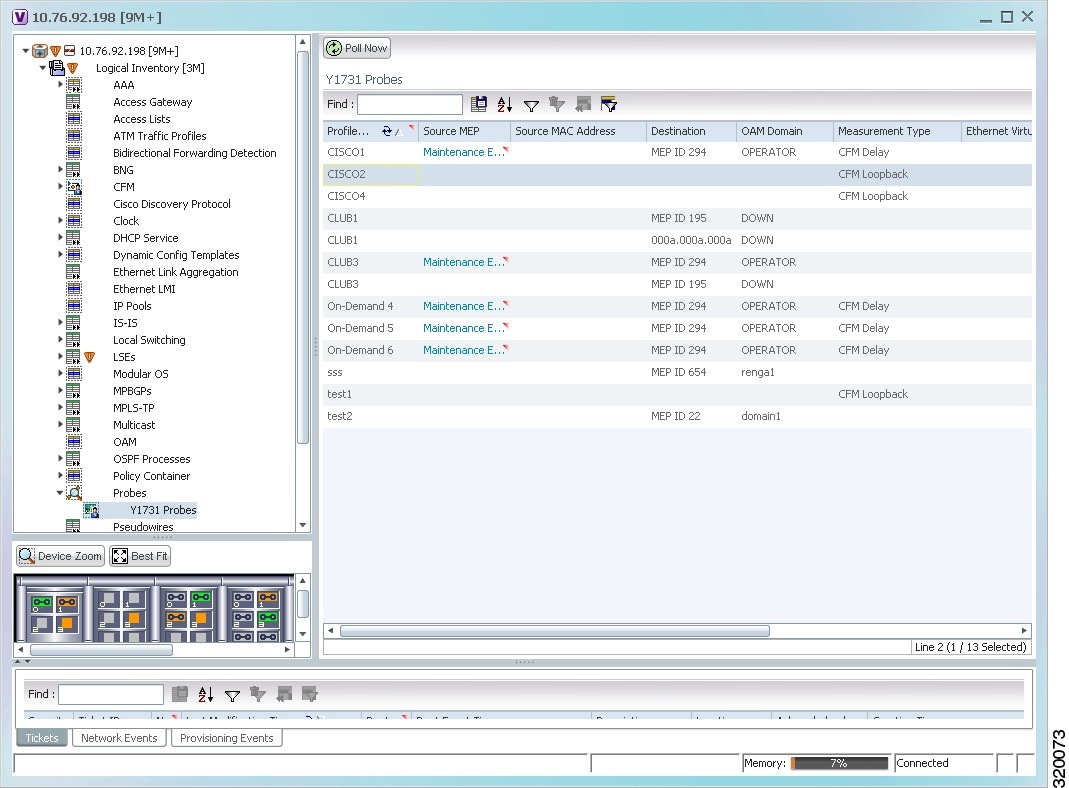
Table 22-1 describes the fields that are displayed in the content pane.
Step 3![]() Right-click a probe and choose Properties to view its properties. The following additional information is displayed in the Probe Properties window for certain devices, such as Cisco CPT devices.
Right-click a probe and choose Properties to view its properties. The following additional information is displayed in the Probe Properties window for certain devices, such as Cisco CPT devices.

Configuring Y.1731 Probes
The following IP SLA-related commands can be launched from the inventory by right-clicking the appropriate node and choosing Commands > Configuration. Your permissions determine whether you can run these commands (see Permissions for Vision Client NE-Related Operations). To find out if a device supports these commands, see the Cisco Prime Network 5.0 Supported Cisco VNEs.
 Feedback