- Overview of Prime Network GUI clients
- Setting Up the Prime Network Clients
- Setting Up Change and Configuration Management
- Setting Up Vision Client Maps
- Setting Up Native Reports
- Setting Up Fault Management and the Events Client Default Settings
- Viewing Devices, Links, and Services in Maps
- Drilling Down into an NE’s Physical and Logical Inventories and Changing Basic NE Properties
- Manage Device Configurations and Software Images
- How Prime Network Handles Incoming Events
- Managing Tickets with the Vision Client
- Viewing All Event Types in Prime Network
- Cisco Path Tracer
- Managing IP Address Pools
- Monitoring AAA Configurations
- Managing DWDM Networks
- Managing MPLS Networks
- Managing Carrier Ethernet Configurations
- Managing Ethernet Networks Using Operations, Administration, and Maintenance Tools
- Monitoring Carrier Grade NAT Configurations
- Monitoring Quality of Service
- Managing IP Service Level Agreement (IP SLA) Configurations
- Monitoring IP and MPLS Multicast Configurations
- Managing Session Border Controllers
- Monitoring BNG Configurations
- Managing Mobile Transport Over Pseudowire (MToP) Networks
- Managing Mobile Networks
- Managing Data Center Networks
- Monitoring Cable Technologies
- Monitoring ADSL2+ and VDSL2 Technologies
- Monitoring Quantum Virtualized Packet Core
- VSS Redundancy System
- Icon Reference
- Permissions Required to Perform Tasks Using the Prime Network Clients
- Correlation Examples
- Managing certificates
Cisco Prime Network User Guide, 5.0
Bias-Free Language
The documentation set for this product strives to use bias-free language. For the purposes of this documentation set, bias-free is defined as language that does not imply discrimination based on age, disability, gender, racial identity, ethnic identity, sexual orientation, socioeconomic status, and intersectionality. Exceptions may be present in the documentation due to language that is hardcoded in the user interfaces of the product software, language used based on RFP documentation, or language that is used by a referenced third-party product. Learn more about how Cisco is using Inclusive Language.
- Updated:
- July 19, 2017
Chapter: Manage Device Configurations and Software Images
- Using the CCM Dashboard
- Managing Device Software Images
- Managing Device Configurations
- What is In the Configuration Archive?
- Protecting and Labeling Important Configurations in the Archive
- Editing an Archive Configuration
- Finding Out What is Different Between Configurations
- Copying a Configuration File to a Central Server
- Are Running and Startup Configs Mismatched? (CiscoIOS and CiscoNexus)
- Copying the Device Files to the Archive (Backups)
- Fixing a Live Device Configuration (Restore)
- Cleaning Up the Archive
- Finding Out What Changed on Live Devices
- Making Sure Devices Conform to Policies Using Compliance Audit
- Wokrflow for Creating Policies and Profiles, and Running a Compliance Audit Job
- Creating a Policy
- Creating a Policy Profile
- Choosing the Devices for the Compliance Audit
- Managing Multilayer Quick Filters for Selected Devices in the Compliance Audit Jobs
- Viewing the Results of a Compliance Audit Job and Running Fixes for Violations
Manage Device Configurations and Software Images
Cisco Prime Network Change and Configuration Management (CCM) provides tools for managing the software images and device configuration files used by the devices in your network.
For information on the devices supported by CCM, see the Cisco Prime Network 5.0 Supported VNEs - Addendum. For its Supported Protocols see the Support for Change and Configuration Management in 5.0 tables.
These topics explain how to use CCM:
- Using the CCM Dashboard
- Managing Device Software Images
- Managing Device Configurations
- Making Sure Devices Conform to Policies Using Compliance Audit
- Using Compliance Audit for Device Compliance
- Checking Image Management, Device Management, and Compliance Audit Jobs
Before using CCM, make sure you have completed the setup steps described in Setting Up Configuration Management.

Note CCM is also the launch point for the following Prime Network features which are described in the Cisco Prime Network 5.0 Customization Guide:
- Prime Network Transaction Manager, which manages and executes activations on groups of devices.
- Prime Network Command Manager, which provides a repository of all commands available in the system, and can be used to create new commands and command sequences which you can apply to groups of devices.
Using the CCM Dashboard
To launch CCM from a web browser, enter the following URL in the address bar:
https:// gateway-IP :8043/ccmweb/ccm/login.htm
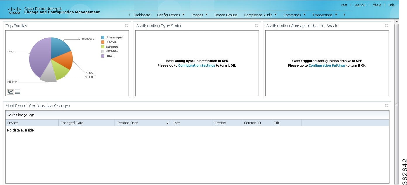
Figure 9-1 shows the CCM Dashboard, which contains four dashlets that display real-time information about the most frequently used software images, any devices with startup and running configurations that are not in sync, and recent device configuration changes.
|
|
|
|---|---|
The four largest device families in the network. (Smaller groups can be viewed by toggling to the tabular form.) From here, you can distribute and activate software images to a selected family. In some cases, the actual name of the device family will not be displayed. For example, if c6sup11, s2t54, and s3223 are displayed in this dashlet, you must search Cisco.com to identify the device families for these devices. The c6sup11 device corresponds to the Cisco Catalyst 6500 Series Supervisor Engine 1A / MSFC1 device family, s2t54 device corresponds to the Cisco Catalyst 6500 Series Supervisor Engine 2T device family, and s3223 device corresponds to the Cisco Catalyst 6500 Series Supervisor Engine 32 / MSFC2A device family. Note If you have enabled the Right to Left (Hebrew) settings in your browser, you may face resizing issues when you hover the cursor over this dashlet. |
|
(Cisco IOS) Devices for which the startup and running device configurations are in sync or not in sync. Whenever a Cisco IOS configuration file is retrieved from a device and copied to the archive, CCM compares the latest version of the startup configuration with the latest version of the running configuration file. If there is a mismatch, CCM adds the device to the list of out-of-sync devices. The information is refreshed whenever you click the Dashboard. A “100% Unavailable” message is displayed when there are no Cisco IOS device images or if the initial configuration sync up setting is not enabled (controlled by the “Enable/Disable Initial config sync up on restart” setting on the Configuration Management Settings page). |
|
Number of device configuration changes detected for each day of the current week. This dashlet is empty when configuration change notification is not enabled (controlled by the “Enable/Disable Event-Triggered Config Archive” setting on the Configuration Management Settings page). |
|
Last five device configuration changes made to devices in the network. This dashlet is empty if configuration change notification is not enabled. It is controlled by the “Enable/Disable Event Triggered Config Archive” setting on the Configuration Management Settings page (see Setting Up Configuration Management). If a device does not support Commit IDs and Diffs, the client displays N/A. |
Use the following icons to toggle between different views in the Top Families, Configuration Sync Status, and Configuration Changes in the Last Week dashlets.


Managing Device Software Images
The CCM Image Management feature provides tools for performing rapid, reliable software upgrades and automates the steps associated with upgrade planning and monitoring. Device software images are stored in the CCM image repository, to which you can add new images by importing them from Cisco.com, from existing devices, from a local file system, or from an external image repository. The images are stored in binary format in the repository, which is in the Prime Network database. Before an image is distributed, CCM performs an upgrade analysis to ensure that the network element is compatible with the image; after an image is distributed, it takes a minimum of 30 minutes for the image to activate. For Cisco IOS XR devices, you can add individual packages, deactivate packages, test changes before committing them, commit changes, and roll packages back to stored rollback points. CCM saves messages that can be used for debugging in NETWORKHOME /XMP_Platform/logs/NEIM.log.
Note Keep these notes in mind when using Image Management:
- Devices must be in the Device Reachable communication state and the Operational investigation state. See Checking the Device State for an explanation of how to check state information.
- CCM does not support special characters for any of the editable fields in the client, including filters.
- Before activating images on multiple devices, install the image on a single device and verify that it operates correctly.
Note![]() If Prime Network is down then debug message is sent to user and no debug message is sent to user when Prime Network is up
If Prime Network is down then debug message is sent to user and no debug message is sent to user when Prime Network is up
The following topics explain how to work with software images and packages:
- Adding New Images to the Repository
- Creating an Image Baseline for New Devices
- Distributing Images and Making Sure They Will Work
- File System Clean Up
- Activating Cisco IOS Software Images
- Performing Cisco IOS XR Software Package Operations
- Cleaning Up the Repository
Adding New Images to the Repository
When images are copied to the repository, they are placed in the storing directory specified on the Image Management Settings page. Images are copied from the storing directory into the repository. Before copying an image, CCM verifies whether the new image is different from the existing image in the repository. If they are the same, CCM does not add it to the repository. By default, the storing directory is NETWORKHOME /NCCMComponents/NEIM/images.
Note![]() Before importing images, make sure internet connectivity is available to the remote server; otherwise, the imported images will not be populated with RAM, boot ROM, and feature set information.
Before importing images, make sure internet connectivity is available to the remote server; otherwise, the imported images will not be populated with RAM, boot ROM, and feature set information.
When you download an image from Cisco.com, CCM creates a job for the download. The job information is saved, along with other job information, in the database.
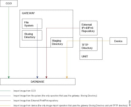
Figure 9-2 illustrates the process of importing images into the Prime Network database.
Figure 9-2 Import Image Operations
To import images into the CCM image repository:
Step 1![]() Choose Images > Repository.
Choose Images > Repository.
Step 2![]() Choose the appropriate method:
Choose the appropriate method:
Step 3![]() Select the images and import them. CCM redirects you to the Jobs page, where you can monitor the status of the import job.
Select the images and import them. CCM redirects you to the Jobs page, where you can monitor the status of the import job.
Step 4![]() Choose Images > Repository again to refresh the list of images.
Choose Images > Repository again to refresh the list of images.
If a field displays NA, the image attributes were not available from the image header. (If pre-existing filters are still in use, you may need to click Clear Filter.) We recommend that you manually enter the information to ensure the accuracy of the upgrade analysis.
After an image is successfully imported, CCM removes any images from the unit TFTP directory, the gateway Staging Directory, and the gateway Storing Directory (for import from Cisco.com only). If you import images from a file system, you must manually delete those files from the gateway Storing Directory.
You can also add informational text to the Comments field. To distribute the images, see Distributing Images and Making Sure They Will Work.
Creating an Image Baseline for New Devices
Use this method to create an image baseline—that is, directly copy images from existing devices to the image repository. This is useful when you add devices from a new device series or family.
For information on devices that support Image Baseline, see the Cisco Prime Network 5.0 Supported VNEs - Addendum.
See Figure 9-2 which illustrates how images are imported from devices into the database.
Note![]() You cannot import tar files from IOS XR devices.
You cannot import tar files from IOS XR devices.
To import images from devices into the CCM image repository:
Step 1![]() Choose Images > Repository.
Choose Images > Repository.
Step 2![]() From the Import drop-down list, choose F rom Devices. The Devices dialog box displays information about the device. For long texts in the Element Type, Software Version, and Running Image fields, hover the cursor over the hyperlink to display the entire contents.
From the Import drop-down list, choose F rom Devices. The Devices dialog box displays information about the device. For long texts in the Element Type, Software Version, and Running Image fields, hover the cursor over the hyperlink to display the entire contents.
Step 3![]() To import images from devices of a specific group, click Select Groups. Click the hyperlinked device group name to view the list of devices that belong to the group. See Setting Up CCM Device Groups for more information on user-defined device grouping.
To import images from devices of a specific group, click Select Groups. Click the hyperlinked device group name to view the list of devices that belong to the group. See Setting Up CCM Device Groups for more information on user-defined device grouping.
Step 4![]() Select the required device group in the Device Groups page and click OK.
Select the required device group in the Device Groups page and click OK.
The devices that belong to the selected device group are highlighted in the Devices page. You can also import all the devices existing in a group. To do so:
–![]() Select a device group and click Import from Group.
Select a device group and click Import from Group.
–![]() Enter the scheduling information as explained after Step 5 and click Import from Group.
Enter the scheduling information as explained after Step 5 and click Import from Group.
Step 5![]() In the Devices page, click Import. A scheduler popup window appears.
In the Devices page, click Import. A scheduler popup window appears.
Note![]() You might be prompted to enter your device access credentials. This option is enabled if, from the Administration client, Global Settings > Security Settings > User Account Settings > Execution of Configuration Operations, you checked the option Ask for user credentials when running configuration operations. This is an enhanced security measure to restrict access to devices.
You might be prompted to enter your device access credentials. This option is enabled if, from the Administration client, Global Settings > Security Settings > User Account Settings > Execution of Configuration Operations, you checked the option Ask for user credentials when running configuration operations. This is an enhanced security measure to restrict access to devices.
Step 6![]() Enter the scheduling information. By default, jobs are scheduled to run as soon as possible.
Enter the scheduling information. By default, jobs are scheduled to run as soon as possible.
Note![]() The time you specify here to schedule the import job is the gateway time.
The time you specify here to schedule the import job is the gateway time.
Step 7![]() If you do not want to use the default transfer protocol, select a different protocol:
If you do not want to use the default transfer protocol, select a different protocol:
For information on the default transfer protocol that each device use, see the Cisco Prime Network 5.0 Supported VNEs - Addendum and the Cisco Prime Network 5.0 Supported Cisco VNEs. For its Supported Protocols see the Support for Change and Configuration Management in 5.0 tables.
Step 8![]() If you have selected two or more devices, click one of the following to specify the operation mode:
If you have selected two or more devices, click one of the following to specify the operation mode:
Note![]() The Device Order box is only available for sequences containing less than 300 devices. CCM sequences the devices based on the order used when the devices were selected.
The Device Order box is only available for sequences containing less than 300 devices. CCM sequences the devices based on the order used when the devices were selected.
Step 9![]() Enter the e-mail ID(s) to which to send a notification after the import job is complete. For two or more users, enter a comma-separated list of e-mail IDs. A notification e-mail is sent based on the e-mail option specified in the Image Management Settings page.
Enter the e-mail ID(s) to which to send a notification after the import job is complete. For two or more users, enter a comma-separated list of e-mail IDs. A notification e-mail is sent based on the e-mail option specified in the Image Management Settings page.
Note![]() Before you enter the e-mail ID(s), ensure that you have set up the SMTP host and SMTP port in the Image Management Settings page (see Setting Up Image Management). The configured e-mail ID(s) will be displayed by default and can be modified if required.
Before you enter the e-mail ID(s), ensure that you have set up the SMTP host and SMTP port in the Image Management Settings page (see Setting Up Image Management). The configured e-mail ID(s) will be displayed by default and can be modified if required.
Step 10![]() Click Import. CCM redirects you to the Jobs page, where you can monitor the status of the import job.
Click Import. CCM redirects you to the Jobs page, where you can monitor the status of the import job.
Note![]() If you import all devices from a device group and, after creating the job, there is a change in the group, CCM updates the job accordingly such that all the devices available in the group at the time of the job execution are considered.
If you import all devices from a device group and, after creating the job, there is a change in the group, CCM updates the job accordingly such that all the devices available in the group at the time of the job execution are considered.
Step 11![]() Choose Images > Repository again to refresh the list of images. If any of the image information could not be retrieved, the field will display NA. (If pre-existing filters are still in use, you may need to click Clear Filter.) We recommend that you manually enter the information to ensure the accuracy of the upgrade analysis.
Choose Images > Repository again to refresh the list of images. If any of the image information could not be retrieved, the field will display NA. (If pre-existing filters are still in use, you may need to click Clear Filter.) We recommend that you manually enter the information to ensure the accuracy of the upgrade analysis.
Step 12![]() Delete files from the storing directory (if applicable) to free space for future imports.
Delete files from the storing directory (if applicable) to free space for future imports.
After the import, you can also add informational text to the Comments field. Normally at this point you will distribute the images; see Distributing Images and Making Sure They Will Work.
Distributing Images and Making Sure They Will Work
CCM can copy an image to a network element without activating it. This lets you perform these tasks before activating the image:
- Find out if there is insufficient memory, clear the disk space for distributing the image or package
- Do an upgrade analysis to check the suitability of the device for the chosen image
If appropriate, the images can be activated as part of the distribution job, and the following tasks can also be performed:
- Commit Cisco IOS XR (so that changes are saved across device reloads).
- Perform a warm upgrade, where one Cisco IOS image can read in and decompress another Cisco IOS image and transfer control to this new image (thus reducing the downtime of a device during planned software upgrades and downgrades).
- Perform an in-service software upgrade (ISSU) for Cisco ASR 903 devices to update the router software with minimal service interruption. CCM performs a s ingle command upgrade that installs a complete set of sub-packages using one command. The device must be configured in SSO redundancy mode. Before you perform an ISSU, you must verify if sufficient memory is available in standby boot flash.
Note![]() Cisco ASR 903 devices must be booted in sub-package mode only through boot flash and not through any sub-directories of boot flash before using CCM to perform an ISSU. For more information, see the Cisco ASR 903 Series Router Chassis Configuration Guide.
Cisco ASR 903 devices must be booted in sub-package mode only through boot flash and not through any sub-directories of boot flash before using CCM to perform an ISSU. For more information, see the Cisco ASR 903 Series Router Chassis Configuration Guide.
In the Activation Scheduler page, check the Boot in Subpackage mode radio button to boot the Cisco ASR 903 devices.
- Perform an in-service software upgrade (ISSU) for Cisco 9000 series devices and CRS devices to update the router software with minimal service interruption. The option to perform ISSU is supported only for SMU packages.
For information on devices that support ISSU, see the Cisco Prime Network 5.0 Supported VNEs - Addendum. For its Supported Protocols see the Support for Change and Configuration Management in 5.0 tables.
CCM uses the image staging location and transport protocol (TFTP, by default) specified on the Image Management Settings page. CCM displays the available upgradeable modules and the storage partitions (if any) on the network element for the image distribution, from which you can choose the storage location you want to use.
The final step is to schedule the distribution job to occur either as soon as possible or at a future date (the default is as soon as possible).
What is Upgrade Analysis?
An upgrade analysis checks the attributes of the selected image, checks certain device features, and generates a separate report for each device. It is required before any image can be distributed. However, even if the upgrade analysis reports errors, CCM will allow you to proceed with the distribution (because an error can be a simple matter of an unpopulated field).
CCM gathers this information from two sources:
- The Image Management repository, which contains information about minimum RAM, minimum Flash, and so on, in the image header.
- The Prime Network inventory, which contains information about the active images on the device, as well as Flash memory, modules, and processor details.
An upgrade analysis verifies that the device contains sufficient RAM or storage, the image is compatible with the device family, and the software version is compatible with the image version running on the device.
Table 9-1 denotes the symbols used on the Distribution page.


Distribute Images to Devices
The following procedure explains how to perform an image distribution. You can also use this procedure to perform an upgrade analysis and then exit the procedure before performing the distribution.
- If you are doing a Cisco IOS XR version upgrade (which upgrades the core package), see Managing Device Software Images for information about other packages that you should upgrade at the same time.
- Make sure you have the permissions to perform the distribute operation. You will not be allowed to schedule a distribution job, if you do not have permissions.
Figure 9-3 illustrates the process of distributing images to devices.
Figure 9-3 Image Distribution Operations

To distribute images and use upgrade analysis:
Step 1![]() Choose Images > Distribute.
Choose Images > Distribute.
Step 2![]() C hoose the device type (IOS or IOS XR) and selection method (by image or package, or by device). It is often easier to start with devices due to the sometimes cryptic nature of software image names. In this example we start with devices.
C hoose the device type (IOS or IOS XR) and selection method (by image or package, or by device). It is often easier to start with devices due to the sometimes cryptic nature of software image names. In this example we start with devices.
Note![]() CCM does not support tar file operations on IOS devices. Tar file operations are supported only on Cisco Catalyst and IOS XR devices.
CCM does not support tar file operations on IOS devices. Tar file operations are supported only on Cisco Catalyst and IOS XR devices.
a.![]() To choose devices of a specific device group, click Select Groups in the table header. Click the hyperlinked device group name to view the list of devices that belong to the group.
To choose devices of a specific device group, click Select Groups in the table header. Click the hyperlinked device group name to view the list of devices that belong to the group.
b.![]() Select the required device group in the Device Groups page and click OK.
Select the required device group in the Device Groups page and click OK.
c.![]() Choose one or more devices and click Next.
Choose one or more devices and click Next.
Step 3![]() CCM displays all images or packages, which are valid for the selected devices from the internal image repository (for example, kickstart images for Cisco Nexus 5000 or Cisco Nexus 7000, and boot configs for Cisco ASR 5000). You can also choose From External Repository from the drop-down list (in the table header) to display the images or packages from the external image repository.
CCM displays all images or packages, which are valid for the selected devices from the internal image repository (for example, kickstart images for Cisco Nexus 5000 or Cisco Nexus 7000, and boot configs for Cisco ASR 5000). You can also choose From External Repository from the drop-down list (in the table header) to display the images or packages from the external image repository.
Note![]() CCM allows image distribution from external repository only through FTP. Make sure you have configured the required credentials for accessing the external image repository in the Image Management Settings page.
CCM allows image distribution from external repository only through FTP. Make sure you have configured the required credentials for accessing the external image repository in the Image Management Settings page.
If you selected Cisco OLT devices, a list of filenames appear. The image files that do not have filename extensions belong to ONUs and image files that have filename extensions are that of an OLT device. For Cisco OLT devices, after you select the required images, the job scheduling page appears.
If you selected Tar file(s) for IOS XR devices, you cannot select any other non-tar file(s), and vice versa.
If you selected an Nexus devices (except for Nx9K), you can select a corresponding compatible image in the Select Compatible Image page, for a selected system image or a kickstart image.
Note![]() Select Compatible Image is only optional. If a compatible image is selected for a System or Kickstart image you can perform both the Distribution and Activation of an image, otherwise you can perform only distribution of an image.
Select Compatible Image is only optional. If a compatible image is selected for a System or Kickstart image you can perform both the Distribution and Activation of an image, otherwise you can perform only distribution of an image.
Choose an image and click Next.
Step 4![]() (Applicable only when distributing Cisco ONU images) After you select the required images, you must configure the image properties for a selected ONU image. From the Select ONU Image Properties pane, click Configure ONU Images.
(Applicable only when distributing Cisco ONU images) After you select the required images, you must configure the image properties for a selected ONU image. From the Select ONU Image Properties pane, click Configure ONU Images.
When you perform a bulk activation for ONUs, the selected image will be applied to the ONU, the details of which matches with the information that you entered in this window .
|
|
|
|---|---|
From the drop-down list, select an image profile to which this image must be distributed. |
|
Click Next. You will be redirected to the Schedule Distribution page.
Step 5![]() In the Select Storage page, choose a storage location by device or for all devices. This specifies where on the network element the image or package will be copied when it is distributed.
In the Select Storage page, choose a storage location by device or for all devices. This specifies where on the network element the image or package will be copied when it is distributed.
Step 6![]() (Not applicable to Cisco OLT devices) Perform an upgrade analysis to check whether the network element has sufficient space for the image or package by clicking Upgrade Analysis. After a few moments, CCM displays the results of the analysis in the Upgrade Analysis column. Click the symbol next to the icon to see the Upgrade Analysis report.
(Not applicable to Cisco OLT devices) Perform an upgrade analysis to check whether the network element has sufficient space for the image or package by clicking Upgrade Analysis. After a few moments, CCM displays the results of the analysis in the Upgrade Analysis column. Click the symbol next to the icon to see the Upgrade Analysis report.
If an error is reported, you will see a prompt asking you to confirm whether or not to proceed with the operation.
Step 7![]() (Not applicable to Cisco OLT devices) If you do not want to distribute any images or packages (for example, if you only wanted to perform a manual upgrade analysis), click Cancel. Otherwise, proceed to Step 8
(Not applicable to Cisco OLT devices) If you do not want to distribute any images or packages (for example, if you only wanted to perform a manual upgrade analysis), click Cancel. Otherwise, proceed to Step 8![]() .
.
Step 8![]() Click Next to open the Schedule Distribution page in the wizard, and complete the schedule information.
Click Next to open the Schedule Distribution page in the wizard, and complete the schedule information.
Note![]() You can proceed with scheduling the distribution only if upgrade analysis is completed for all the devices (spanning across multiple pages) in the Select Storage page.
You can proceed with scheduling the distribution only if upgrade analysis is completed for all the devices (spanning across multiple pages) in the Select Storage page.
|
|
|
|---|---|
When the distribution job should run. Note The time you specify here to schedule the distribution job is the gateway time. |
|
Overrides the default transfer protocol (as configured on the Image Management Settings page). |
|
(Optional) In case of insufficient memory, use the Clear Flash option (under Flash Properties). This deletes any one file (other than the running image) and recovers the disk space occupied by the file. This procedure is repeated until adequate space is available in the selected flash. |
|
E-mail ID(s) to which to send a notification after the scheduled distribution job is complete. For two or more users, enter a comma-separated list of e-mail IDs. A notification e-mail is sent based on the e-mail option specified in the Image Management Settings page. |
|
(Optional) Adds packages during distribution for Cisco IOS XR devices. Note While adding tar file(s) in the Select Packages page of the wizard, you can select the Install Add Package(s) and Schedule Activation check boxes separately and then schedule the jobs. Note If you have selected pie files in the Select Packages page in the wizard, CCM generates a tar file, which will be copied and added to the IOS XR devices. |
|
(Optional) Starts an activation job once the images or packages are distributed (immediately or at future time). For multiple devices, we recommend that you perform the activation separately from the distribution. Not applicable to ONU image distribution. |
|
For multi-device jobs, controls the job processes for both distribution and activation. If you chose Sequentially, you can also do the following:
Note If the job includes a reload, choose Sequentially. Otherwise, routers in the connectivity path of other routers may reload and cause problems. |
|
Commits the packages after activation for Cisco IOS XR devices. |
|
(For Cisco IOS only) Activates the Warm Upgrade feature to reduce the device downtime during the distribution process. |
|
Activates in-service software upgrade (ISSU) to update the router software with minimal service interruption. For information on devices that support ISSU, see the Cisco Prime Network 5.0 Supported VNEs - Addendum. For its Supported Protocols see the Support for Change and Configuration Management in 5.0 tables. |
Step 9![]() Click Finished. You are redirected to the Jobs page, where you can check the status of the distribution job.
Click Finished. You are redirected to the Jobs page, where you can check the status of the distribution job.
Note![]() Distribution fails if a timeout occurs after 30 minutes. You can view the job results for information on why the distribution failed. Remember to delete older images and packages from the staging directory.
Distribution fails if a timeout occurs after 30 minutes. You can view the job results for information on why the distribution failed. Remember to delete older images and packages from the staging directory.
File System Clean Up
While performing upgrade analysis, if the available storage space in the device is lesser than the selected image size, then the user can increase the storage space by following the procedure provided below:
Step 1![]() Click the Action link under the Delete Images option in the Select Storage page. This opens the Delete Image Table window with a list of files.
Click the Action link under the Delete Images option in the Select Storage page. This opens the Delete Image Table window with a list of files.
Step 2![]() Check the check box near each file to select the files to be deleted in the Delete Image Table window.
Check the check box near each file to select the files to be deleted in the Delete Image Table window.
Step 3![]() Click Apply. This deletes the files that are selected, thus increasing the storage space.
Click Apply. This deletes the files that are selected, thus increasing the storage space.
Note![]() You can view the increased storage space by clicking the Upgrade Analysis Result option in the Select Storage page without repeating the upgrade analysis process.The selected files in the Action window are actually not deleted when you click the Apply button. File deletion in device happens only when you schedule the distribution job.
You can view the increased storage space by clicking the Upgrade Analysis Result option in the Select Storage page without repeating the upgrade analysis process.The selected files in the Action window are actually not deleted when you click the Apply button. File deletion in device happens only when you schedule the distribution job.
Activating Cisco IOS Software Images
These topics describe the tasks you can perform from the Activate page:
- Activating Cisco IOS Software Images
- Activating After Performing Boot Priority Modification for Cisco StarOS Devices
When a new Cisco IOS image is activated on a device, it becomes the running image on the disk. Deactivated images remain on the disk to be removed by a user. Older images are automatically deactivated.
Make sure you have the permissions to perform the activate operation. You will not be allowed to schedule an activation job, if you do not have permissions.
Distributing and activating the images should not be done from standby or alias boot flash. For example, for Cisco Catalyst 6500 Virtual Switching System (VSS), you must use the images from sup-boot disk for activation. Similarly, for Cisco ASR 903 Series Aggregation Services Routers, you must use the images from boot flash for activation.
Activating Cisco IOS Software Images
To activate a Cisco IOS image on a network element:
Step 1![]() Choose Images > Activate.
Choose Images > Activate.
Step 2![]() From the Cisco Devices tab, choose IOS by activation method (IOS by Images or IOS by Devices). It is often easier to start with devices due to the sometimes cryptic nature of software image names. In this example we start with devices.
From the Cisco Devices tab, choose IOS by activation method (IOS by Images or IOS by Devices). It is often easier to start with devices due to the sometimes cryptic nature of software image names. In this example we start with devices.
Step 3![]() CCM displays all managed devices. It also displays the images that are currently running on the devices. You can filter by device name, IP address, element type, running image, or software version.
CCM displays all managed devices. It also displays the images that are currently running on the devices. You can filter by device name, IP address, element type, running image, or software version.
a.![]() To choose devices of a specific device group, click Select Groups in the table header. Click the hyperlinked device group name to view the list of devices that belong to the group.
To choose devices of a specific device group, click Select Groups in the table header. Click the hyperlinked device group name to view the list of devices that belong to the group.
b.![]() Select the required device group in the Device Groups page and click OK.
Select the required device group in the Device Groups page and click OK.
Note![]() If you selected CPT devices, upon choosing the devices, CCM directs you to the Schedule Activation page directly. You will not be able to choose specific images for CPT devices.
If you selected CPT devices, upon choosing the devices, CCM directs you to the Schedule Activation page directly. You will not be able to choose specific images for CPT devices.
c.![]() Choose one or more devices and click Next. CCM displays all images or packages which are valid for the selected devices from the internal image repository (for example, kickstart images for Cisco Nexus 5000 or Cisco Nexus 7000, and boot configs for Cisco ASR 5000). You can also choose From External Repository from the drop-down list (in the table header) to display the images or packages from the external image repository.
Choose one or more devices and click Next. CCM displays all images or packages which are valid for the selected devices from the internal image repository (for example, kickstart images for Cisco Nexus 5000 or Cisco Nexus 7000, and boot configs for Cisco ASR 5000). You can also choose From External Repository from the drop-down list (in the table header) to display the images or packages from the external image repository.
Step 4![]() CCM displays all images or packages which are valid for the selected devices from the internal image repository. CCM displays only root level bin files for selection.
CCM displays all images or packages which are valid for the selected devices from the internal image repository. CCM displays only root level bin files for selection.
Step 5![]() Choose the image that you want to activate on the devices, and click Next.
Choose the image that you want to activate on the devices, and click Next.
Step 6![]() CCM performs an image analysis. Check the Image Analysis page to see if analysis was successful. Click the icon in the Analysis column to get information about why the operation can or cannot proceed.
CCM performs an image analysis. Check the Image Analysis page to see if analysis was successful. Click the icon in the Analysis column to get information about why the operation can or cannot proceed.
If it cannot proceed, you will not be permitted to continue. Otherwise, click Next.
Step 7![]() Enter the scheduling information in the Schedule Activation page. By default, jobs are scheduled to run as soon as possible.
Enter the scheduling information in the Schedule Activation page. By default, jobs are scheduled to run as soon as possible.
Note![]() The time you specify here to schedule the activation job is the gateway time.
The time you specify here to schedule the activation job is the gateway time.
Step 8![]() Enter the e-mail ID(s) to which to send a notification after the scheduled activation job is complete. For two or more users, enter a comma-separated list of e-mail IDs. A notification e-mail is sent based on the e-mail option specified in the Image Management Settings page.
Enter the e-mail ID(s) to which to send a notification after the scheduled activation job is complete. For two or more users, enter a comma-separated list of e-mail IDs. A notification e-mail is sent based on the e-mail option specified in the Image Management Settings page.
Step 9![]() (For Cisco IOS only) Activate the Warm Upgrade option, which allows a Cisco IOS image to read in and decompress another Cisco IOS image and transfer control to this new image (thus reducing the downtime of a device during planned software upgrades and downgrades).
(For Cisco IOS only) Activate the Warm Upgrade option, which allows a Cisco IOS image to read in and decompress another Cisco IOS image and transfer control to this new image (thus reducing the downtime of a device during planned software upgrades and downgrades).
Step 10![]() Check the ISSU option, to update the router software with minimal service interruption.
Check the ISSU option, to update the router software with minimal service interruption.
Step 11![]() Click one of the following to specify the operation mode, if you have selected two or more devices in the Select Devices page.
Click one of the following to specify the operation mode, if you have selected two or more devices in the Select Devices page.
Step 12![]() Click Finished to schedule the activation.
Click Finished to schedule the activation.
Activating After Performing Boot Priority Modification for Cisco StarOS Devices
To modify boot priorities for Cisco StarOS devices and then perform activation:
Step 1![]() Choose Images > Activate > IOS and the activation method (by Devices).
Choose Images > Activate > IOS and the activation method (by Devices).
Step 2![]() Choose the Cisco StarOS device family from the table header. CCM displays all managed Cisco StarOS devices. It also displays the images that are currently running on the devices. You can filter by device name, IP address, element type, running image, or software version.
Choose the Cisco StarOS device family from the table header. CCM displays all managed Cisco StarOS devices. It also displays the images that are currently running on the devices. You can filter by device name, IP address, element type, running image, or software version.
Step 3![]() Select a Cisco StarOS device, choose the Perform Edit Boot Priorities option from the drop-down menu in the table header, and then click Next. The Select Boot Config page appears.
Select a Cisco StarOS device, choose the Perform Edit Boot Priorities option from the drop-down menu in the table header, and then click Next. The Select Boot Config page appears.
Step 4![]() Click the Edit Boot Priorities hyperlink. The Current Boot Priorities table lists the existing boot configuration files with their priorities.
Click the Edit Boot Priorities hyperlink. The Current Boot Priorities table lists the existing boot configuration files with their priorities.
Step 5![]() Provide the following inputs to set up and fetch the desired boot priorities:
Provide the following inputs to set up and fetch the desired boot priorities:
Step 6![]() Click Go to generate boot priorities based on the inputs provided. The modified boot priorities are listed in the table below.
Click Go to generate boot priorities based on the inputs provided. The modified boot priorities are listed in the table below.
Step 7![]() You can choose to perform one of the following for each row in the table:
You can choose to perform one of the following for each row in the table:
- Edit—Modify the boot priority value, the image name, and the configuration file, if required. The modified boot priority value should be unique.
- Delete—Delete the boot configuration priority.
- Add Row—Add boot priorities to the existing list. CCM generates boot priority values based on the inputs provided. Note that only the top ten boot priorities are considered for the device.
Step 8![]() Click Save. A dialog box appears listing the existing and the modified boot priorities for your confirmation.
Click Save. A dialog box appears listing the existing and the modified boot priorities for your confirmation.
Step 9![]() Click Save to confirm and apply the boot priority changes.
Click Save to confirm and apply the boot priority changes.
Step 10![]() You can then schedule the activation as explained in Activating Cisco IOS Software Images.
You can then schedule the activation as explained in Activating Cisco IOS Software Images.
Activate OLT Images
Step 1![]() Choose Images > Activate.
Choose Images > Activate.
Step 2![]() Select OLT from the drop-down list. Click Next.
Select OLT from the drop-down list. Click Next.
Only one image is present in the OLT device. Upon performing the activation operation, the OLT image present in the device is activated.
You will be directed to the schedule page.
Activate ONU Images in Bulk
OLT images can be activated using two modes—Manual or Auto. Using the Auto mode, you can activate an image that is marked as the default image. However, using the Auto mode, you can change the image configuration and then activate the image on the selected device.
Step 1![]() Choose Images > Activate.
Choose Images > Activate.
Step 2![]() From the Cisco Devices tab, choose IOS by activation method (IOS by Images or IOS by Devices). It is often easier to start with devices due to the sometimes cryptic nature of software image names. In this example we start with devices.
From the Cisco Devices tab, choose IOS by activation method (IOS by Images or IOS by Devices). It is often easier to start with devices due to the sometimes cryptic nature of software image names. In this example we start with devices.
Step 3![]() Prime Network displays all managed devices. It also displays the images that are currently running on the devices. You can filter by device name, IP address, element type, running image, or software version.
Prime Network displays all managed devices. It also displays the images that are currently running on the devices. You can filter by device name, IP address, element type, running image, or software version.
a.![]() To choose devices of a specific device group, click Select Groups in the table header. Click the hyperlinked device group name to view the list of devices that belong to the group.
To choose devices of a specific device group, click Select Groups in the table header. Click the hyperlinked device group name to view the list of devices that belong to the group.
a.![]() Select the required device group in the Device Groups page and click OK.
Select the required device group in the Device Groups page and click OK.
a.![]() Choose one or more devices and click Next. Prime Network displays all images or packages which are valid for the selected devices from the internal image repository.
Choose one or more devices and click Next. Prime Network displays all images or packages which are valid for the selected devices from the internal image repository.
Step 4![]() Choose the image that you want to activate on the devices. Choose Bulk Upgrade from the drop-down list and then choose the type of mode. Click Next. The following combinations are possible:
Choose the image that you want to activate on the devices. Choose Bulk Upgrade from the drop-down list and then choose the type of mode. Click Next. The following combinations are possible:
Step 1![]() From the Selected OLTs for Manual Upgrade pane, click the Configure ONU Images hyperlink. This window displays the ONU images that are present in the OLT device.
From the Selected OLTs for Manual Upgrade pane, click the Configure ONU Images hyperlink. This window displays the ONU images that are present in the OLT device.
Using this window, the image properties can be configured. To configure image properties, click the respective cell in the table, and change the value. Click Save.
Step 2![]() Choose an image and click Manual Upgrade. Set the slot number, PON number, and ONU ID to which the selected image must be applied. To apply the image on all slots, PONs, or ONUs, select All . The image is subsequently applied to all ONUs which have the upgrade mode set to Off in the device.
Choose an image and click Manual Upgrade. Set the slot number, PON number, and ONU ID to which the selected image must be applied. To apply the image on all slots, PONs, or ONUs, select All . The image is subsequently applied to all ONUs which have the upgrade mode set to Off in the device.
Step 3![]() Click Commit or Activate, as required. Clicking Commit will activate the image when the ONU is restarted. Clicking Activate will active the image immediately. If you choose neither Activate nor Commit, the image will overwrite the existing inactive image. Click Manual Upgrade. You are redirected to the original pane.
Click Commit or Activate, as required. Clicking Commit will activate the image when the ONU is restarted. Clicking Activate will active the image immediately. If you choose neither Activate nor Commit, the image will overwrite the existing inactive image. Click Manual Upgrade. You are redirected to the original pane.
You are redirected to the Schedule Activation job page.
Step 1![]() The selected OLTs appear in the Selected OLTs for Auto Upgrade pane. Set the slot and PON to which you want the image to be activated.
The selected OLTs appear in the Selected OLTs for Auto Upgrade pane. Set the slot and PON to which you want the image to be activated.
- Auto—An ONU profile can have several images, of which only one is default. When you activate the image in Auto mode, only the image which is the default image for the selected ONU profile is applied.
- Planned—The image with which the software version matches with that of the selected ONU is applied.
To configure image properties, click the respective cell in the table, and change the value. Click Save.
You are directed to the Schedule Activation job page.
Activate ONU Image Individually
Step 1![]() Choose Images > Activate.
Choose Images > Activate.
Step 2![]() Choose an OLT image and click Next.
Choose an OLT image and click Next.
Step 3![]() From the Select ONU pane, set the slot, PON, and ONU and click on Show ONU Image hyperlink. The Show ONU Images dialog box displays the list of images that can be activated for the selected ONU.
From the Select ONU pane, set the slot, PON, and ONU and click on Show ONU Image hyperlink. The Show ONU Images dialog box displays the list of images that can be activated for the selected ONU.
Step 4![]() From the Show ONU Images dialog box, choose an image. Of the two images that are displayed, you must choose an image that is currently not active.
From the Show ONU Images dialog box, choose an image. Of the two images that are displayed, you must choose an image that is currently not active.
Activate Nexus OS Image Individually
For Nexus devices you can distribute two images such as System image and Kickstart image. if you want to distribute any image to Nexus device (Except Nx9k), in the Select image page, select either of any one of the image and in "Select Compatible image" corresponding compatible image will be shown. This is optional page. This page is applicable only for Nexus device.
Step 1![]() Choose Images > Activate.
Choose Images > Activate.
Step 2![]() Choose an Nexus device and click Next.
Choose an Nexus device and click Next.
Step 3![]() From the Select Image pane, set the slot, PON, and ONU and click on Show ONU Image hyperlink. The Show ONU Images dialog box displays the list of images that can be activated for the selected ONU.
From the Select Image pane, set the slot, PON, and ONU and click on Show ONU Image hyperlink. The Show ONU Images dialog box displays the list of images that can be activated for the selected ONU.
Step 4![]() From the Show ONU Images dialog box, choose an image. Of the two images that are displayed, you must choose an image that is currently not active.
From the Show ONU Images dialog box, choose an image. Of the two images that are displayed, you must choose an image that is currently not active.
Step 5![]() Click Next. You are directed to the Schedule Activation job page.
Click Next. You are directed to the Schedule Activation job page.
Copy and Distribute BulkStat File for Star OS Devices
You can copy and distribute BulkStat file along with image files for StarOS devices such as ASR5500, or SI or DI devices.
Step 1![]() Choose Images > Distribute.
Choose Images > Distribute.
Step 2![]() In the Distribute Images window, in the Select Devices area, choose from the Available Devices filter fields choose a device and device name of the same family. For example, ASR5k, or SI, or DI.
In the Distribute Images window, in the Select Devices area, choose from the Available Devices filter fields choose a device and device name of the same family. For example, ASR5k, or SI, or DI.
Figure 9-4 Select a ASR 5K or SI or DI Device

Step 4![]() In the Select Image area, select an image for distribution to the selected device as shown in Figure 9-5..
In the Select Image area, select an image for distribution to the selected device as shown in Figure 9-5..

Step 6![]() In the Select Boot config & Bulkstat files area, If you click the Select Bulkstats button, a dialog box appears with available Bulkstat files for upload as shown in Figure 9-6.
In the Select Boot config & Bulkstat files area, If you click the Select Bulkstats button, a dialog box appears with available Bulkstat files for upload as shown in Figure 9-6.
Figure 9-6 Select BulkStat files

Step 7![]() Select a text file or multiple text files along with the image files for distribution to devices.
Select a text file or multiple text files along with the image files for distribution to devices.
Step 9![]() In the Select Storage area, from the Storage to be used for all devices list box, choose a storage.
In the Select Storage area, from the Storage to be used for all devices list box, choose a storage.
Step 10![]() Enter the Schedule distribution details, if required.
Enter the Schedule distribution details, if required.
Step 12![]() In the Image Management Jobs page, choose the device name and thenclick the Success link. The Job Details dialog box appears as shown in Figure 9-7.
In the Image Management Jobs page, choose the device name and thenclick the Success link. The Job Details dialog box appears as shown in Figure 9-7.

Step 13![]() Click OK to view the distributed job details for the selected device.
Click OK to view the distributed job details for the selected device.
Performing Cisco IOS XR Software Package Operations
Note![]() We recommend that you do not commit the package change until the device runs with its configuration for a period of time, until you are sure the change is appropriate. In that way, the change is not yet persisted across device reloads.
We recommend that you do not commit the package change until the device runs with its configuration for a period of time, until you are sure the change is appropriate. In that way, the change is not yet persisted across device reloads.
Notes on Cisco IOS XR Packages
Package management includes the add, activate, deactivate, commit, and rollback operations on Cisco IOS XR devices. Before you perform any of these operations, read the following:
- When doing a version upgrade (which upgrades the core package and involves a router reload) on a Cisco IOS XR device, all of the packages on the router should be upgraded at the same time, as part of the same job. For example, if the c12k-mini, c12k-mgbl, c12k-mpls, c12k-k9sec, and c12k-mcast packages are on the router at version 3.4.1, when upgrading to version 3.5.0, all of the packages must be upgraded at the same time to version 3.5.0.
Note![]() An upgrade pie is required only when you upgrade Cisco IOS XR devices from version 3.x to 4.x. You must deactivate and remove the upgrade pie, if you wish to perform any install operations, including the install commit operation on the devices upgraded from 3.x to 4.x.
An upgrade pie is required only when you upgrade Cisco IOS XR devices from version 3.x to 4.x. You must deactivate and remove the upgrade pie, if you wish to perform any install operations, including the install commit operation on the devices upgraded from 3.x to 4.x.
- When upgrading the core router package (such as c12k-mini or comp-hfr-mini), the manageability package (such as c12k-mgbl or hfr-mgbl-p) must be upgraded at the same time to ensure that the router remains manageable after the reload.
- Cisco IOS XR routers support the clear install rollback oldest x command, that allows you to manage the number of rollback points maintained on the router. Executing this CLI command periodically on the router allows you to limit the number of rollback points. When executing this command, you must ensure that at least one valid rollback point is always maintained to enable CCM to show the package status correctly. We recommend that you maintain about 20 rollback points on the router.
- CCM does not support upgrading a router running Cisco IOS software to Cisco IOS XR software.
For more information, refer to the System Management Configuration Guide for the Cisco IOS XR release and device of interest.
Adding Cisco IOS XR Packages
Image Management supports package addition as a separate operation for Cisco IOS XR devices. To complete the package management life cycle, Image Management supports adding a package from a pie file and a tar file, which is already present in the Cisco IOS XR device storage.
Make sure you have the permissions to perform package addition. You will not be allowed to schedule a package addition job, if you do not have permissions.
To add packages for Cisco IOS XR devices:
Step 1![]() Choose Images > Package Add. The Package Add wizard displays all the Cisco IOS XR devices in the Select Device(s) page.
Choose Images > Package Add. The Package Add wizard displays all the Cisco IOS XR devices in the Select Device(s) page.
Step 2![]() Select a device and click Next to open the Select Package(s) page. CCM displays all the packages available for the selected device.
Select a device and click Next to open the Select Package(s) page. CCM displays all the packages available for the selected device.
Step 3![]() Choose the package(s) that you want to add for the selected device and click Next to open the Schedule Package Addition page in the wizard.
Choose the package(s) that you want to add for the selected device and click Next to open the Schedule Package Addition page in the wizard.
Step 4![]() Enter the scheduling information. By default, jobs are scheduled to run as soon as possible.
Enter the scheduling information. By default, jobs are scheduled to run as soon as possible.
Note![]() The time you specify here to schedule the package addition job is the gateway time.
The time you specify here to schedule the package addition job is the gateway time.
Step 5![]() If you have selected two or more devices in the Select Devices page, click one of the following to specify the operation mode:
If you have selected two or more devices in the Select Devices page, click one of the following to specify the operation mode:
Step 6![]() Enter the e-mail ID(s) to which to send a notification after the scheduled package addition job is complete. For two or more users, enter a comma-separated list of e-mail IDs. A notification e-mail is sent based on the e-mail option specified in the Image Management Settings page.
Enter the e-mail ID(s) to which to send a notification after the scheduled package addition job is complete. For two or more users, enter a comma-separated list of e-mail IDs. A notification e-mail is sent based on the e-mail option specified in the Image Management Settings page.
Step 7![]() Click Finished. CCM schedules the job and redirects you to the Jobs page, where you can monitor the status of the job.
Click Finished. CCM schedules the job and redirects you to the Jobs page, where you can monitor the status of the job.
Activating, Deactivating, and Deleting Cisco IOS XR Packages
Note![]() For Cisco IOS XR devices, we recommend that you do not commit the package change until the device runs with its configuration for a period of time, until you are sure the change is appropriate. In that way, the change is not yet persisted across device reloads.
For Cisco IOS XR devices, we recommend that you do not commit the package change until the device runs with its configuration for a period of time, until you are sure the change is appropriate. In that way, the change is not yet persisted across device reloads.
- If you are doing a Cisco IOS XR version upgrade (which upgrades the core package), see Managing Device Software Images for information about other packages that you should upgrade at the same time.
To activate or deactivate a Cisco IOS XR package, or delete a Cisco IOS XR package from a device:
Step 1![]() Choose Images > Activate > IOS-XR and the activation method (by Packages or Devices.). It is often easier to start with devices due to the sometimes cryptic nature of software image names. In this example we start with devices.
Choose Images > Activate > IOS-XR and the activation method (by Packages or Devices.). It is often easier to start with devices due to the sometimes cryptic nature of software image names. In this example we start with devices.
Step 2![]() CCM displays all managed devices. (It also displays the packages that are currently running on the devices.) From this page you can also view the running package of the Cisco IOS XR device.
CCM displays all managed devices. (It also displays the packages that are currently running on the devices.) From this page you can also view the running package of the Cisco IOS XR device.
a.![]() To choose devices of a specific device group, click Select Groups. In the Device Groups page, you can view the user-defined device groups. Click the hyperlinked device group name to view the list of devices that belong to the group. See Setting Up CCM Device Groups for more information on user-defined device grouping.
To choose devices of a specific device group, click Select Groups. In the Device Groups page, you can view the user-defined device groups. Click the hyperlinked device group name to view the list of devices that belong to the group. See Setting Up CCM Device Groups for more information on user-defined device grouping.
b.![]() Select the required device group in the Device Groups page and click OK.
Select the required device group in the Device Groups page and click OK.
c.![]() Choose one or more devices and click Next. CCM displays all packages which are valid for the selected devices. You can filter your results by package name and version.
Choose one or more devices and click Next. CCM displays all packages which are valid for the selected devices. You can filter your results by package name and version.
d.![]() Choose the packages that you want to activate on the devices, and click Next.
Choose the packages that you want to activate on the devices, and click Next.
Step 3![]() Specify the operations you want to perform. You can perform different operations on different devices or the same operation on all devices (by selecting the desired operation from the Use the following Operation for all Packages drop-down list in the table header). When you select a device, CCM will display all of the packages that are installed on the device.
Specify the operations you want to perform. You can perform different operations on different devices or the same operation on all devices (by selecting the desired operation from the Use the following Operation for all Packages drop-down list in the table header). When you select a device, CCM will display all of the packages that are installed on the device.
a.![]() Choose a package operation for each package. Cisco IOS XR packages can be removed from a device only if they have been deactivated. If you want to apply the same operation to all packages, choose the operation from the Use the following Operation for all Packages drop-down list in the table header, and click Apply.
Choose a package operation for each package. Cisco IOS XR packages can be removed from a device only if they have been deactivated. If you want to apply the same operation to all packages, choose the operation from the Use the following Operation for all Packages drop-down list in the table header, and click Apply.
b.![]() (Optional) Check Test Only to run a test of the activation (or deactivation) procedure on the device. This will not change the real device configuration. (This is similar to using the Compatibility Check option in the rollback process.)
(Optional) Check Test Only to run a test of the activation (or deactivation) procedure on the device. This will not change the real device configuration. (This is similar to using the Compatibility Check option in the rollback process.)
c.![]() Click Next. The Package Analysis page is displayed. Check the Package Analysis page to see if analysis was successful. Click the icon in the Analysis column to get information about why the operation can or cannot proceed (it will be one of the icons listed in Table 9-1). If it cannot proceed, you will not be permitted to continue. Otherwise, click Next.
Click Next. The Package Analysis page is displayed. Check the Package Analysis page to see if analysis was successful. Click the icon in the Analysis column to get information about why the operation can or cannot proceed (it will be one of the icons listed in Table 9-1). If it cannot proceed, you will not be permitted to continue. Otherwise, click Next.
Step 4![]() Enter the scheduling information. By default, jobs are scheduled to run as soon as possible.
Enter the scheduling information. By default, jobs are scheduled to run as soon as possible.
Note![]() The time you specify here to schedule the activation job is the gateway time.
The time you specify here to schedule the activation job is the gateway time.
Step 5![]() Enter the e-mail ID(s) to which to send a notification after the scheduled activation job is complete. For two or more users, enter a comma-separated list of e-mail IDs. A notification e-mail is sent based on the e-mail option specified in the Image Management Settings page.
Enter the e-mail ID(s) to which to send a notification after the scheduled activation job is complete. For two or more users, enter a comma-separated list of e-mail IDs. A notification e-mail is sent based on the e-mail option specified in the Image Management Settings page.
Step 6![]() Check the ISSU option, to update the router software with minimal service interruption. For information on devices that support ISSU, see the Cisco Prime Network 5.0 Supported VNEs - Addendum. For its Supported Protocols see the Support for Change and Configuration Management in 5.0 tables.
Check the ISSU option, to update the router software with minimal service interruption. For information on devices that support ISSU, see the Cisco Prime Network 5.0 Supported VNEs - Addendum. For its Supported Protocols see the Support for Change and Configuration Management in 5.0 tables.
Step 7![]() Check the Commit check box to commit the packages after activation.
Check the Commit check box to commit the packages after activation.
Note![]() We recommend that you do not commit the package change until the device runs with its configuration for a period of time, until you are sure the change is appropriate. In that way, the change is not yet persisted across device reloads.
We recommend that you do not commit the package change until the device runs with its configuration for a period of time, until you are sure the change is appropriate. In that way, the change is not yet persisted across device reloads.
Step 8![]() Click one of the following to specify the operation mode, if you have selected two or more devices in the Select Devices page.
Click one of the following to specify the operation mode, if you have selected two or more devices in the Select Devices page.
Step 9![]() Click Finished to schedule the activation.
Click Finished to schedule the activation.
Step 10![]() After the job completes:
After the job completes:
- For Test Only jobs, repeat this procedure to activate the packages.
- If you activated or deactivated a Cisco IOS XR package, remember to commit your changes. However, we recommend that you do not commit the package change until the device runs with its configuration for a period of time, until you are sure the change is appropriate. In that way, the change is not yet persisted across device reloads. See Committing Cisco IOS XR Packages Across Device Reloads.
Synchronizing and Upgrading Satellites for Cisco ASR 9000 Devices
CCM provides satellite support for Cisco ASR 9000 devices. Satellites are used to enhance performance bandwidth of Cisco ASR 9000 devices. Each satellite is a Cisco IOS device connected to the Cisco ASR 9000 device. Multiple satellites can be connected to a single Cisco ASR 9000 device and all communications to the satellites happen only through the Cisco ASR 9000 device. Each satellite has its own configuration and software image.
CCM provides the following support for Cisco ASR 9000 device with satellites:
- Synchronization of all satellites together.
- Activation of the satellite pie image on Cisco ASR 9000 device with and without synchronization of satellites. You must run a CLI/XML command to check for compatibility and then push the image to the remote satellite.
Synchronize All Satellites Without Performing an Activation
To synchronize all satellites together without activation:
Step 1![]() Choose Images > Activate > IOS-XR and the activation method (by Devices).
Choose Images > Activate > IOS-XR and the activation method (by Devices).
Step 2![]() Choose the Cisco ASR 9000 device family and the Sync Satellites option from the Select Operations drop-down menu in the table header.
Choose the Cisco ASR 9000 device family and the Sync Satellites option from the Select Operations drop-down menu in the table header.
CCM displays all managed Cisco ASR 9000 series devices having satellites. (It also displays the packages that are currently running on the devices.)
Step 3![]() Click Next to schedule the synchronization for all the satellites together. You cannot select a particular satellite for synchronization. The Select Operation function is not applicable for the Sync Satellites option.
Click Next to schedule the synchronization for all the satellites together. You cannot select a particular satellite for synchronization. The Select Operation function is not applicable for the Sync Satellites option.
Step 4![]() In the Schedule Activation page, provide the scheduling information for synchronization of all satellites.
In the Schedule Activation page, provide the scheduling information for synchronization of all satellites.
Note![]() The time you specify here to schedule the activation job is the gateway time.
The time you specify here to schedule the activation job is the gateway time.
Step 5![]() Check the Sync Satellite(s) check box and click Finished. The Sync Satellite(s) check box is available only for Cisco ASR 9000 devices having satellites.
Check the Sync Satellite(s) check box and click Finished. The Sync Satellite(s) check box is available only for Cisco ASR 9000 devices having satellites.
Activate Satellite Image on Cisco ASR 9000 Device With or Without Synchronization
To activate a satellite image on the Cisco ASR 9000 device with/without satellite synchronization:
Step 1![]() Choose Images > Activate > IOS-XR and the activation method (by Devices).
Choose Images > Activate > IOS-XR and the activation method (by Devices).
Step 2![]() Choose the Cisco ASR 9000 device family and the Activate and/or Sync Satellites option from the Select Operations drop-down menu in the table header.
Choose the Cisco ASR 9000 device family and the Activate and/or Sync Satellites option from the Select Operations drop-down menu in the table header.
Step 3![]() Perform Step 3 through Step 7 in Activating, Deactivating, and Deleting Cisco IOS XR Packages topic.
Perform Step 3 through Step 7 in Activating, Deactivating, and Deleting Cisco IOS XR Packages topic.
Step 4![]() Check the Sync Satellite(s) check box, if you wish to upgrade and synchronize the satellites. The Sync Satellite(s) check box is available only for Cisco ASR 9000 devices having satellites.
Check the Sync Satellite(s) check box, if you wish to upgrade and synchronize the satellites. The Sync Satellite(s) check box is available only for Cisco ASR 9000 devices having satellites.
Note![]() Synchronization of satellites is done, only if the operation selected is activation or deactivation. Otherwise, synchronization will not happen even if this check box is selected.
Synchronization of satellites is done, only if the operation selected is activation or deactivation. Otherwise, synchronization will not happen even if this check box is selected.
Step 5![]() Click Finished to schedule the activation and/or synchronization.
Click Finished to schedule the activation and/or synchronization.
Committing Cisco IOS XR Packages Across Device Reloads
Committing a Cisco IOS XR package makes the device package configurations persist across device reloads. The commit operation also creates a rollback point on the device. See Rolling Back Cisco IOS XR Packages, for more information on rollback points.
Note![]() We recommend that you do not commit package changes until the device runs with its configuration for a period of time, until you are sure the change is appropriate. In that way, the change is not yet persisted across device reloads.
We recommend that you do not commit package changes until the device runs with its configuration for a period of time, until you are sure the change is appropriate. In that way, the change is not yet persisted across device reloads.
- Verify that the package to be committed is operating properly (for example, by doing a show status command).
- Make sure you have the permissions to perform the commit operation. You will not be allowed to schedule a commit job, if you do not have permissions.
To commit a package after it has been activated, deactivated, or rolled back:
Step 1![]() Choose Images > Commit.
Choose Images > Commit.
Step 2![]() Choose the network elements with the packages you want to commit.
Choose the network elements with the packages you want to commit.
Step 3![]() Click one of the following (in the table header) to specify the commit mode:
Click one of the following (in the table header) to specify the commit mode:
Step 4![]() Enter the scheduling information.
Enter the scheduling information.
Note![]() The time you specify here to schedule the commit job is the gateway time.
The time you specify here to schedule the commit job is the gateway time.
Step 5![]() Enter the e-mail ID(s) to which to send a notification e-mail after the scheduled commit job is complete. For two or more users, enter a comma-separated list of e-mail IDs. A notification e-mail is sent based on the e-mail option specified in the Image Management Settings page.
Enter the e-mail ID(s) to which to send a notification e-mail after the scheduled commit job is complete. For two or more users, enter a comma-separated list of e-mail IDs. A notification e-mail is sent based on the e-mail option specified in the Image Management Settings page.
Step 6![]() Click Commit. By default, jobs are scheduled to run as soon as possible.
Click Commit. By default, jobs are scheduled to run as soon as possible.
Rolling Back Cisco IOS XR Packages
Rolling back a Cisco IOS XR package reverts the device packages to a previous installation state—specifically, to a package installation rollback point. If a package has been removed from a device, all rollback points associated with the package are also removed and it is no longer possible to roll back to that point.
- Read Managing Device Software Images, for information about managing rollback points on Cisco IOS XR devices.
- Make sure you have the permissions to perform the rollback operation. You will not be allowed to schedule a rollback job, if you do not have permissions.
To roll back a Cisco IOS XR package:
Step 1![]() Choose Images > Rollback. CCM displays all Cisco IOS XR devices. You can filter the results by using the Quick Filter option.
Choose Images > Rollback. CCM displays all Cisco IOS XR devices. You can filter the results by using the Quick Filter option.
Step 2![]() Choose the network elements. CCM populates the rollback points for the selected device package.
Choose the network elements. CCM populates the rollback points for the selected device package.
Step 3![]() Choose a rollback ID from the Rollback ID drop-down list. The Rollback Point Details field lists the packages that were active when that ID was created.
Choose a rollback ID from the Rollback ID drop-down list. The Rollback Point Details field lists the packages that were active when that ID was created.
Step 4![]() To view all of the packages associated with the rollback point, place the mouse cursor on the Rollback Point Details field; see Figure 9-8 for an example. To view the time stamp associated with the selected rollback, see the value displayed in the Time Stamp field.
To view all of the packages associated with the rollback point, place the mouse cursor on the Rollback Point Details field; see Figure 9-8 for an example. To view the time stamp associated with the selected rollback, see the value displayed in the Time Stamp field.
Note![]() The date and time stamps are displayed according to the local time zone settings of the client.
The date and time stamps are displayed according to the local time zone settings of the client.
Figure 9-8 Packages Rollback Page with Rollback Point Details
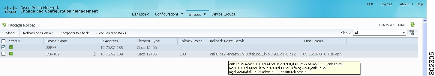
Step 5![]() Click OK to close the popup window.
Click OK to close the popup window.
Note![]() If a package has been deleted from the repository, the rollback points of the package are still displayed in CCM. If you choose a rollback point for a deleted package, the rollback will fail. The job results popup provides information explaining why it failed.
If a package has been deleted from the repository, the rollback points of the package are still displayed in CCM. If you choose a rollback point for a deleted package, the rollback will fail. The job results popup provides information explaining why it failed.
Step 6![]() (Optional) Click Compatibility Check in the table header to run a test of the rollback procedure on the device. This will not change the real device configuration. (This is similar to using the Test Only option in the activation process.)
(Optional) Click Compatibility Check in the table header to run a test of the rollback procedure on the device. This will not change the real device configuration. (This is similar to using the Test Only option in the activation process.)
Step 7![]() Click Rollback or Rollback and Commit.
Click Rollback or Rollback and Commit.
Note![]() We recommend that you do not commit package changes until the device runs with its configuration for a period of time, until you are sure the change is appropriate. In that way, the change is not yet persisted across device reloads. See Committing Cisco IOS XR Packages Across Device Reloads.
We recommend that you do not commit package changes until the device runs with its configuration for a period of time, until you are sure the change is appropriate. In that way, the change is not yet persisted across device reloads. See Committing Cisco IOS XR Packages Across Device Reloads.
Step 8![]() Enter the scheduling information.
Enter the scheduling information.
Note![]() The time you specify here to schedule the rollback job is the gateway time.
The time you specify here to schedule the rollback job is the gateway time.
Step 9![]() Enter the e-mail ID(s) to which to send a notification after the scheduled rollback job is complete. For two or more users, enter a comma-separated list of e-mail IDs. A notification e-mail is sent based on the e-mail option specified in the Image Management Settings page.
Enter the e-mail ID(s) to which to send a notification after the scheduled rollback job is complete. For two or more users, enter a comma-separated list of e-mail IDs. A notification e-mail is sent based on the e-mail option specified in the Image Management Settings page.
Note![]() Before you enter the e-mail ID(s), ensure that you have set up the SMTP host and SMTP port in the Image Management Settings page (see Setting Up Image Management). The configured e-mail ID(s) will be displayed by default and can be modified if required.
Before you enter the e-mail ID(s), ensure that you have set up the SMTP host and SMTP port in the Image Management Settings page (see Setting Up Image Management). The configured e-mail ID(s) will be displayed by default and can be modified if required.
Cleaning Up the Repository
The repository is purged according to the settings described in Setting Up Image Management. When files are removed from the repository, this does not affect files that are installed on the device. However, deleting a package could cause a rollback point to become unexecutable. If a package or version of a package that is associated with a specific rollback point is removed, it will no longer be possible to roll back to that point. See Rolling Back Cisco IOS XR Packages.
To delete images from the CCM image repository:
Step 1![]() Choose Images > Repository.
Choose Images > Repository.
Step 2![]() Select the image you want to delete and click the Delete button (with red X) in the table header.
Select the image you want to delete and click the Delete button (with red X) in the table header.
Step 3![]() To collectively delete all images in the repository, click the Delete All button in the table header. You will see a prompt asking you to confirm whether or not to proceed with the operation.
To collectively delete all images in the repository, click the Delete All button in the table header. You will see a prompt asking you to confirm whether or not to proceed with the operation.
Step 4![]() Click OK to confirm and image(s) available in the repository will be deleted.
Click OK to confirm and image(s) available in the repository will be deleted.
Managing Device Configurations
The CCM Configuration Management feature enables you to control and track changes that are made to a device configuration. It uses a change management feature to detect ongoing changes to devices in two ways:
- When doing periodic archiving of device configurations. If CCM detects a change in a configuration file, it will get the new version of the file from the device and copy it to the archive.
- When a configuration change notification is received from a device. This is called event-triggered archiving. You can configure CCM to copy a new version of a configuration file to the archive whenever a change is detected, or to queue the changes and then copy the files to the archive according to a schedule.
By default, neither of these methods are enabled. You can configure them from the Configuration Management Settings page (see Setting Up Configuration Management).
Change Logs provide information on the changes made to devices in the network, sorted by their time stamp. The Configuration Management Settings page controls how long these logs are saved. CCM saves messages that can be used for debugging in NETWORKHOME /XMP_Platform/logs/ConfigArchive.log.
Note Keep these notes in mind when using Configuration Management:
- Devices must be in the Device Reachable communication state and the Operational investigation state. See Checking the Device State for an explanation of how to check state information.
- CCM does not support special characters for any of the editable fields in the client, including filters.
- Cisco IOS devices using SNMPv3 must be configured with write permission for the CISCO-CONFIG-COPY-MIB MIB group.
The following topics explain how to work with device configurations:
- What is In the Configuration Archive?
- Protecting and Labeling Important Configurations in the Archive
- Editing an Archive Configuration
- Finding Out What is Different Between Configurations
- Copying a Configuration File to a Central Server
- Are Running and Startup Configs Mismatched? (Cisco IOS and Cisco Nexus)
- Copying the Device Files to the Archive (Backups)
- Fixing a Live Device Configuration (Restore)
- Cleaning Up the Archive
- Finding Out What Changed on Live Devices
What is In the Configuration Archive?
Choose Configurations > Archives to view the contents of the archive. The configuration archive maintains copies of device configuration files, storing them in the database. Configuration files are stored in readable format, as received from the device. You can edit existing archive files and save for deployment at a later time. The edited archive files are available in the Edited Archive tab. The total number of archives available in the database is also displayed in the header. The configuration, after deployment, can also be restored to the original state. Users can only see devices that are in their device scope. For enhanced security, you might be prompted to enter your device access credentials when you try viewing device details or when you try performing configuration changes on devices. This option is enabled if, from the Administration client , Global Settings > Security Settings > User Account Settings > Execution of Configuration Operations, you checked the option Ask for user credentials when running configuration operations.
The Archived Configurations page displays the following information about each configuration file.
|
|
|
|---|---|
Name of device. Click the icon next to the device name to open a popup that displays device properties. Additional information is listed depending on the device type: |
|
An internally-used number. A version will not have an associated configuration file under the following circumstances:
Click a version number hyperlink to launch the Device Configuration Viewer, from which you can view the contents of a configuration file. |
|
Type of configuration for each device. For information on the devices that support the different configuration type, see the Cisco Prime Network 5.0 Supported VNEs - Addendum. |
|
Date and time of last change, displayed according to the local time zone settings of the client. For Cisco CPT, Cisco StarOS, and Cisco ME 4600 series OLT devices, this field displays N/A. |
|
For Cisco Nexus OS devices, this field displays the virtual device context (VDC) name. For Cisco 7600 series devices, this field displays the module name. For Cisco StarOS devices, this field displays the boot configuration files with their priorities. For Cisco CPT 200 and Cisco CPT 600 devices, this field displays the operation mode details. For other devices, this field displays N/A.
Note |
|
(Cisco IOS XR only) ID that identifies the last configuration change on the device (maximum number saved is 100). |
Note![]() CCM does not support the view, compare, edit, and, edit and restore operations if the configuration file is in binary format.
CCM does not support the view, compare, edit, and, edit and restore operations if the configuration file is in binary format.
Protecting and Labeling Important Configurations in the Archive
Assigning labels to configuration files is a clear, simple way to identify important configurations and convey critical information. You can manage labels by choosing Labels > Manage.
- Adding a label adds it to the catalog where it is made available to all users. Add labels by clicking Add Row.
- Deleting a label unassigns the label from configurations that are using it. Likewise, if you edit a label, the change is applied to all configurations using the label.
- Unassigning a label does not delete the label from the catalog.
- Labels with the “do not purge” property will not be purged from the archive (the delete action is disabled). When calculating the total number of archives to see if the maximum has been reached and archives should be purged, CCM does not include configurations with this label in the total (see Setting Up Configuration Management).
Editing an Archive Configuration
You can edit an existing device archive file and save the edited file. This edited archived file is stored in the Prime Network database, and the edited file can be deployed at any time. This can be viewed from the Edited Archive tab, in the Archive page. Every time you edit and save an existing file, a new version is added in the database, and is also listed in the Edited Archive page.
Note![]() The option to edit existing device archive file and save the edited file is not available for non-Cisco devices.
The option to edit existing device archive file and save the edited file is not available for non-Cisco devices.
Edit archive files following the procedure below:
Step 1![]() From the Archive page, choose a configuration file, and click Edit.
From the Archive page, choose a configuration file, and click Edit.
Step 2![]() Edit and save the configuration file.
Edit and save the configuration file.
An edited archive version is created. This edited version will belong to the same configuration type as that of the original archive file.
Finding Out What is Different Between Configurations
CCM allows you to compare two configuration files that are saved in the archive and display them side by side, highlighting configuration differences and allowing you to move between them. CCM excludes a small set of commands by default, such as the NTP clock rate (which constantly changes on a managed network element but is not considered a configuration change). You can change the excluded commands list as described in Setting Up Configuration Management. Additions, deletions, and excluded values are color-coded as shown in the following example.
Figure 9-9 Compare Configurations Dialog Box
You can compare any types of configurations as long as they run on the same operating system. However, you cannot compare a Cisco IOS configuration with Cisco IOS XR configuration.
The following are typical scenarios for using the compare function:
- Compare the latest and next-to-latest configuration to see the most recent change.
- Compare Cisco IOS running and startup configurations to see how they are out of sync.
- Compare the configurations on two different devices to find out how they are different.
- Compare the configurations after eliminating excluded 5.0 from comparison.
Note![]() When you are trying to compare an archive with an active startup, running, or admin configuration, if there is a change in the device configuration, CCM initiates a backup job and creates a latest version of the device configuration file. You can view the latest version of the configuration file in the Archived Configurations page.
When you are trying to compare an archive with an active startup, running, or admin configuration, if there is a change in the device configuration, CCM initiates a backup job and creates a latest version of the device configuration file. You can view the latest version of the configuration file in the Archived Configurations page.
Step 1![]() Choose Configurations > Archives.
Choose Configurations > Archives.
Step 2![]() Locate the archives you want to compare. You can click the Version hyperlink next to a device to open the Device Configuration Viewer and quickly view the contents of the configuration file.
Locate the archives you want to compare. You can click the Version hyperlink next to a device to open the Device Configuration Viewer and quickly view the contents of the configuration file.
Step 3![]() You can choose to do the following:
You can choose to do the following:
|
|
|
|---|---|
Copying a Configuration File to a Central Server
You can export configurations to an FTP or SFTP server that is specified on the Configuration Management Settings page. They are exported as a.cfg (configuration) file.
Configuration files are saved using the following format:
deviceName - configurationType - version - configChangeTimestamp .cfg
For example, the following file would contain the 18th version of a running configuration for the device named 7200-5, saved on March 27, 2010 at 2:40:30 P.M:
7200-5-RUNNING_CONFIG-18-2010327144030.cfg
Note![]() Export of configuration files of IPv6 devices to servers running Windows OS is not supported.
Export of configuration files of IPv6 devices to servers running Windows OS is not supported.
- Export location and required credentials, and (for e-mails) SMTP host and port are configured on the Configuration Management Settings page.
- Specified FTP or SFTP server must have sufficient free space to accommodate the exported configurations. Also, the destination subdirectory on the FTP or SFTP server must have the required permissions.
To export configuration files:
Step 1![]() Choose Configurations > Archives and locate the archives you want to export. You can click the Version hyperlink next to a device to open the Device Configuration Viewer and quickly view the contents of the configuration file.
Choose Configurations > Archives and locate the archives you want to export. You can click the Version hyperlink next to a device to open the Device Configuration Viewer and quickly view the contents of the configuration file.
Step 2![]() Click Export and set the desired schedule and enter the e-mail ID(s) to which to send a notification after the scheduled export job is complete. For two or more users, enter a comma-separated list of e-mail IDs. A notification e-mail is sent based on the e-mail option specified in the Configuration Management Settings page.
Click Export and set the desired schedule and enter the e-mail ID(s) to which to send a notification after the scheduled export job is complete. For two or more users, enter a comma-separated list of e-mail IDs. A notification e-mail is sent based on the e-mail option specified in the Configuration Management Settings page.
Note![]() The time you specify here to schedule the export job is the gateway time.
The time you specify here to schedule the export job is the gateway time.
Step 3![]() Click Export. The export job is created and you are redirected to the Job Manager page, where you can monitor the status of the job.
Click Export. The export job is created and you are redirected to the Job Manager page, where you can monitor the status of the job.
Are Running and Startup Configs Mismatched? (Cisco IOS and Cisco Nexus)
Cisco IOS and Cisco Nexus series devices contain a startup and running configuration file. The startup configuration is loaded when a device is restarted. Ongoing changes to the device are applied to the running configuration. As a result, unless the running configuration is saved as the startup configuration, upon a device restart, any changes would be lost. It is therefore important to ensure that the device startup and running configurations are in sync. When CCM synchronizes a file, it overwrites the startup configuration on the device with the configuration that is currently running on the device.
Whenever a configuration file is retrieved from a device and copied to the archive (that is, backed up), CCM compares the latest version of the startup configuration with the latest version of the running configuration file. If there is a mismatch, CCM adds the device to the list of out-of-sync devices.
For Cisco Nexus series devices, CCM backs up the startup and running configurations for all VDCs configured in the device. If there is a mismatch between the startup and running configurations of a VDC, CCM creates an out-of-sync entry for that VDC.
Note![]() The synchronize operation affects only the configurations running on the device. It does not affect any configuration files that are saved in the archive.
The synchronize operation affects only the configurations running on the device. It does not affect any configuration files that are saved in the archive.
The Dashboard maintains a Configuration Sync Status pie chart that shows how many devices have out-of-sync startup and running configuration files. When you click the pie chart (or choose Configurations > Synchronize), you are directed to the Out of Sync Devices page, where CCM lists all of the out-of-sync devices in tabular format. The information is refreshed whenever you choose Configurations > Synchronize.
Make sure the specified FTP or SFTP server must have sufficient free space to accommodate the exported configurations. Also, the destination subdirectory on the FTP or SFTP server must have the required permissions.
To view differences and synchronize configurations:
Step 1![]() Choose Configurations > Synchronize. CCM lists all out-of-sync devices, the date and time when the device configurations were last changed, and when the files were last archived. Figure 9-10 provides an example. The date and time are displayed according to the local time zone settings of the client.
Choose Configurations > Synchronize. CCM lists all out-of-sync devices, the date and time when the device configurations were last changed, and when the files were last archived. Figure 9-10 provides an example. The date and time are displayed according to the local time zone settings of the client.
Figure 9-10 Configuration Synchronization - Out of Sync Devices Page
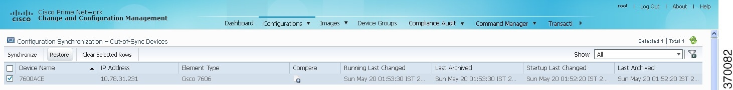
Step 2![]() Click the Compare icon to launch the Compare Configuration window, which provides a side-by-side view of the two configurations and highlights the differences.
Click the Compare icon to launch the Compare Configuration window, which provides a side-by-side view of the two configurations and highlights the differences.
Step 3![]() Choose the network elements you want to synchronize. This directs CCM to overwrite the startup configuration on the device with the configuration that is currently running.
Choose the network elements you want to synchronize. This directs CCM to overwrite the startup configuration on the device with the configuration that is currently running.
Step 4![]() Click Synchronize. The Schedule Synchronization page opens.
Click Synchronize. The Schedule Synchronization page opens.
Step 5![]() Set the desired schedule and enter the e-mail ID(s) to which to send a notification after the scheduled synchronization job is complete. For two or more users, enter a comma-separated list of e-mail IDs. The time you specify here to schedule the synchronization job is the gateway time.
Set the desired schedule and enter the e-mail ID(s) to which to send a notification after the scheduled synchronization job is complete. For two or more users, enter a comma-separated list of e-mail IDs. The time you specify here to schedule the synchronization job is the gateway time.
Note![]() You might be prompted to enter your device access credentials. This option is enabled if, from the Administration client, Global Settings > Security Settings > User Account Settings > Execution of Configuration Operations, you checked the option Ask for user credentials when running configuration operations. This is an enhanced security measure restrict access to devices.
You might be prompted to enter your device access credentials. This option is enabled if, from the Administration client, Global Settings > Security Settings > User Account Settings > Execution of Configuration Operations, you checked the option Ask for user credentials when running configuration operations. This is an enhanced security measure restrict access to devices.
Step 6![]() Click Synchronize. CCM schedules the job and redirects you to the Jobs page, where you can monitor the status of the job.
Click Synchronize. CCM schedules the job and redirects you to the Jobs page, where you can monitor the status of the job.
Copying the Device Files to the Archive (Backups)
Backing up a device configuration entails getting a copy of the configuration file from the device, and copying that file to the configuration archive. As part of the backup procedures, it is compared with the latest archived version of the same type (e.g. running with running, startup with startup). A new version of the file is archived only if the two files are different. If the number of archived versions exceeds the maximum, the oldest archive is purged (according to the values on the Configuration Management Settings page). Configurations marked with a “do not purge” label are not removed from the archive by the auto-purging procedures.
This topic explains how to perform a manual backup. CCM also performs automatic backups according to the specifications on the Global Settings page (see Checking Prime Network Global Settings for CCM Operations). Manual backups do not affect the automatic backups that are controlled from the Global Settings page; they are completely independent of each other.
What Is Backed Up to the Archive
The following table provides the types of configuration files that are backed up to the archive per different types of devices.
Files are automatically backed up to the archive according to the values on the Configuration Management Settings page. To perform an on-demand backup of configuration files to the archive:
Step 1![]() Choose Configurations > Backup. CCM lists all devices with the following status symbols as shown in Figure 9-11.
Choose Configurations > Backup. CCM lists all devices with the following status symbols as shown in Figure 9-11.
Step 2![]() Choose the devices with files you want to back up.
Choose the devices with files you want to back up.
Figure 9-11 Configuration Backup Page
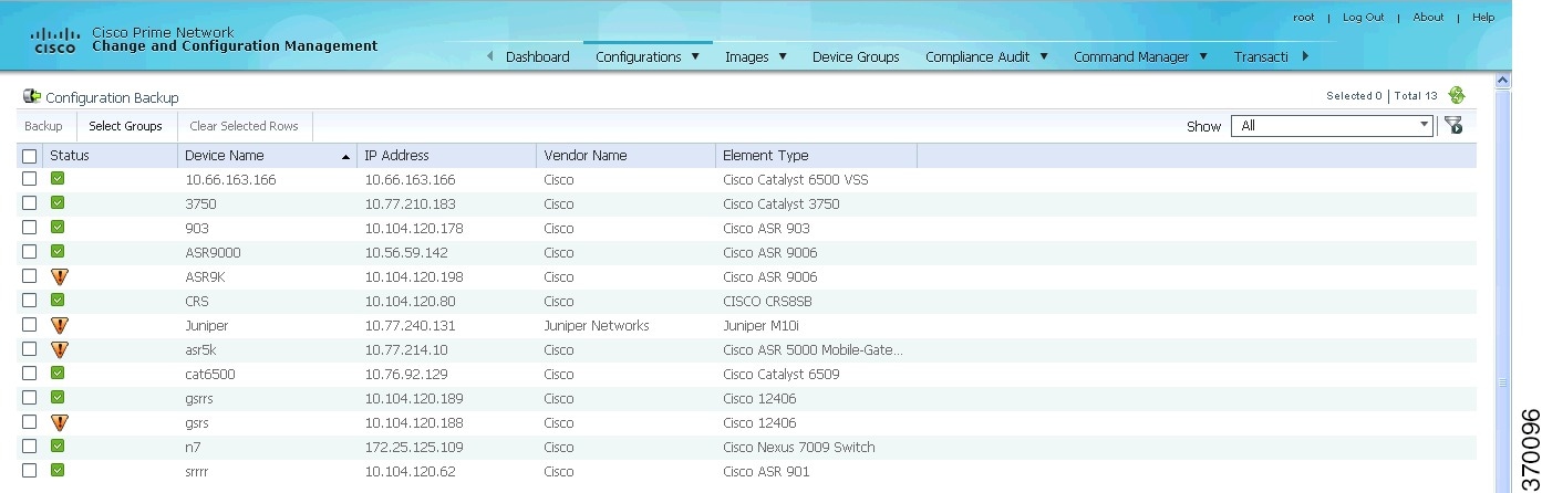
Step 3![]() To choose devices from a specific device group, click Select Groups. Click the hyperlinked device group name to view the list of devices that belong to the group.
To choose devices from a specific device group, click Select Groups. Click the hyperlinked device group name to view the list of devices that belong to the group.
Step 4![]() Select the required device group in the Device Groups page and click OK. The devices that belong to the selected device group are highlighted in the Configuration Backup page. You can also schedule a backup simultaneously for all the devices existing in a group:
Select the required device group in the Device Groups page and click OK. The devices that belong to the selected device group are highlighted in the Configuration Backup page. You can also schedule a backup simultaneously for all the devices existing in a group:
- Select a device group and click Backup Groups.
- Enter the scheduling information as explained after Step 5 and click Backup Groups.
Step 5![]() In the Configuration Backup page, click Backup to configure the backup schedule. By default, the backup is performed as soon as possible. Other schedule choices (once, periodically, weekly, and so forth) are activated when you deselect Start as Soon as Possible. The time you specify here to schedule the backup job is the gateway time.
In the Configuration Backup page, click Backup to configure the backup schedule. By default, the backup is performed as soon as possible. Other schedule choices (once, periodically, weekly, and so forth) are activated when you deselect Start as Soon as Possible. The time you specify here to schedule the backup job is the gateway time.
Note![]() You might be prompted to enter your device access credentials. This option is enabled if, from the Administration client, Global Settings > Security Settings > User Account Settings > Execution of Configuration Operations, you checked the option Ask for user credentials when running configuration operations. This is an enhanced security measure restrict access to devices.
You might be prompted to enter your device access credentials. This option is enabled if, from the Administration client, Global Settings > Security Settings > User Account Settings > Execution of Configuration Operations, you checked the option Ask for user credentials when running configuration operations. This is an enhanced security measure restrict access to devices.
Step 6![]() Enter the e-mail ID(s) to which to send a notification after the schedule backup job is complete. For two or more users, enter a comma-separated list of e-mail IDs. A notification e-mail is sent based on the e-mail option specified in the Configuration Management Settings page.
Enter the e-mail ID(s) to which to send a notification after the schedule backup job is complete. For two or more users, enter a comma-separated list of e-mail IDs. A notification e-mail is sent based on the e-mail option specified in the Configuration Management Settings page.
Step 7![]() Click Backup. CCM schedules the job and when the job is completed a pop-up appears as shown in Figure 9-12.
Click Backup. CCM schedules the job and when the job is completed a pop-up appears as shown in Figure 9-12.
Figure 9-12 Job Create Successfully Message

Step 8![]() Click the hyperlinked Click here to open the Configuration Management Jobs page or click OK to close and return to the Configuration Backup page.
Click the hyperlinked Click here to open the Configuration Management Jobs page or click OK to close and return to the Configuration Backup page.
Note![]() If a backup is scheduled for an entire device group and if there is a change in the group by addition or deletion of devices after job creation, CCM updates the job accordingly such that all the devices available in the group at the time of execution of the job are considered for backup.
If a backup is scheduled for an entire device group and if there is a change in the group by addition or deletion of devices after job creation, CCM updates the job accordingly such that all the devices available in the group at the time of execution of the job are considered for backup.
Step 9![]() In the Configuration Management Jobs page, click the hyperlinked LastRun Result (Success/Partial Success/Failure) against a particular job in the Jobs table.
In the Configuration Management Jobs page, click the hyperlinked LastRun Result (Success/Partial Success/Failure) against a particular job in the Jobs table.
To export completed job results in XLS format, click the hyperlinked Success lastrun result. The Job Details page appears as shown in Figure 9-13.

Step 10![]() Click Export Result to export and download the job results in a XLS format.
Click Export Result to export and download the job results in a XLS format.
To view the archived backup job details:
Step 11![]() In the Job Details page, click the Include Archive Details check box, and then click Export Result. This allows you to export and download the backup information with the latest archived version in XLS format.
In the Job Details page, click the Include Archive Details check box, and then click Export Result. This allows you to export and download the backup information with the latest archived version in XLS format.
Note![]() If devices do not have previous archive details, IP Address, Device Type, and the Last Archived Details columns in the Exported Result report shows NA status.
If devices do not have previous archive details, IP Address, Device Type, and the Last Archived Details columns in the Exported Result report shows NA status.
Figure 9-14 Include Archive Details

If you clear the Include Archive Details check box, the Export Result report will have only the current job details
Step 12![]() Click OK to close and return to the Configuration Management Jobs page.
Click OK to close and return to the Configuration Management Jobs page.
Fixing a Live Device Configuration (Restore)
CCM performs the configuration restore operation in either overwrite or merge mode. As part of restore operation, the configuration files are backed up again after the restore procedure is complete.
- Overwrite mode—CCM supports restoring configuration in overwrite mode on all supported devices. CCM overwrites the existing configuration on the device with a configuration file from the archive. After the restore operation is performed, the device configuration is identical to the configuration that was chosen from the archive.
- Merge mode—CCM merges the selected configuration file from the archive with the configuration on the device. New commands in the archived version—that is, commands that are not in the device’s current configuration—are pushed to the device. After the restore operation, the device configuration file retains its original commands, but it also contains new commands from the archived version.
For information on the devices that support restore operation in overwrite and merge modes, see the Cisco Prime Network 5.0 Supported VNEs and the Cisco Prime Network 5.0 Supported VNEs - Addendum.
By default, CCM uses the restore mode setting (overwrite or merge) that is specified in the Configuration Management Settings page (see Checking Prime Network Global Settings for CCM Operations. However, you can modify the default mode while scheduling the restore operation. If you have selected the overwrite mode, you can use the Use Merge on Failure option to restore the files in merge mode, if overwrite mode fails.
If you select the devices by checking the check box next to Devices (in the table headline), only the first 100 devices in the first page are selected. Click Next to move to the next 100 devices. If you filter the devices based on a parameter, only the filtered details are displayed, and by default, no row is selected. If you selected all the entries in a page, and then deselected one or few options from the selection, and then move to the subsequent pages to select all the devices from the Devices (in the table headline), the selection in the previous page disappears.
- Make sure you have installed Flash Player version 10 or higher to view the Configuration Restore page.
- Make sure you have the permissions to perform the restore operation. You will not be allowed to schedule a restore job, if you do not have permissions.
Step 1![]() Choose Configurations > Restore. CCM lists all configuration files in the archive. Figure 9-15 shows an example of a filtered page.
Choose Configurations > Restore. CCM lists all configuration files in the archive. Figure 9-15 shows an example of a filtered page.
Figure 9-15 Configuration Restore Page
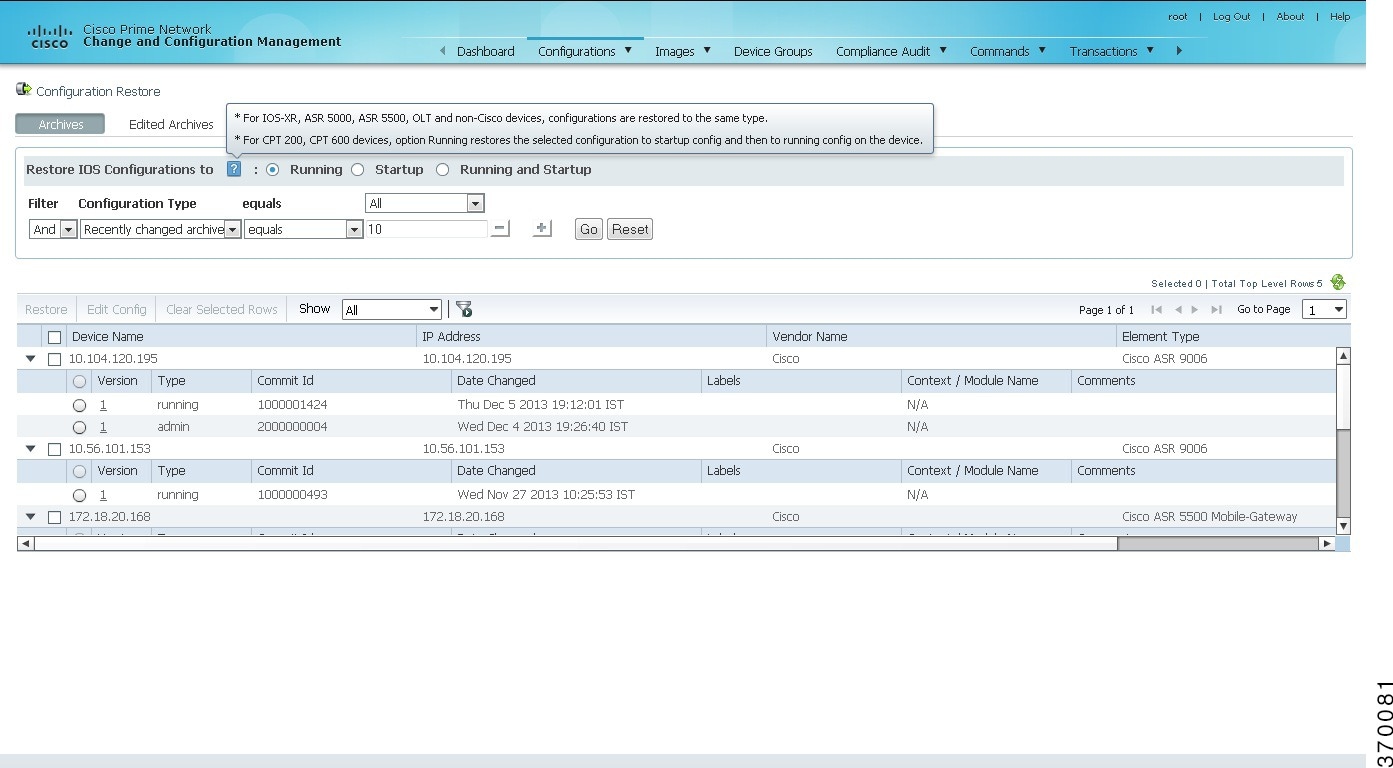
Step 2![]() (Cisco IOS only) Specify the type of configuration files you want to restore: Running, Startup, or both. If you choose to restore to startup configuration, CCM will first copy the file to running configuration and then to startup configuration.
(Cisco IOS only) Specify the type of configuration files you want to restore: Running, Startup, or both. If you choose to restore to startup configuration, CCM will first copy the file to running configuration and then to startup configuration.
If you choose to restore to Running and Startup configuration, CCM will first deploy the configuration archive to the running configuration on the device and then CCM will replace the startup configuration on the device with the modified running configuration.
Step 3![]() Choose the configuration files you want to restore. You can click the arrow mark next to the device name to view the different versions of the configuration file of the device. You can also click the Version hyperlink to view the contents of a file. If the file is a binary file, clicking the version hyperlink does not open the various versions of the configuration file.
Choose the configuration files you want to restore. You can click the arrow mark next to the device name to view the different versions of the configuration file of the device. You can also click the Version hyperlink to view the contents of a file. If the file is a binary file, clicking the version hyperlink does not open the various versions of the configuration file.
If you prefer to restore an edited archive file, open the Edited Archive tab. Select the files and click Next. The list of devices that belong to the same device family with respect to the selected edited configuration is displayed. Select the required devices. Skip to Step 5.
Step 4![]() If you want to edit a file before restoring it, click Edit Config (edited files are restored only in merge mode). You can view the details of the selected configuration file in the Configuration Editor page as shown in Figure 9-16.
If you want to edit a file before restoring it, click Edit Config (edited files are restored only in merge mode). You can view the details of the selected configuration file in the Configuration Editor page as shown in Figure 9-16.
Note![]() If you selected non-Cisco or OLT (GPON) devices, the Edit Config button is disabled.
If you selected non-Cisco or OLT (GPON) devices, the Edit Config button is disabled.
Figure 9-16 Configuration Edit
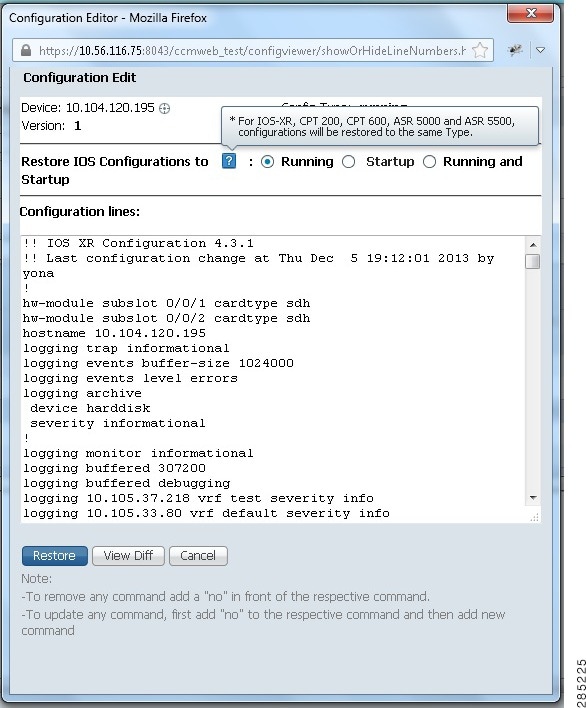
Edit the configuration 5.0, as required. Note the following:
Step 5![]() Click Restore. The Config Restore Schedule dialog box opens.
Click Restore. The Config Restore Schedule dialog box opens.
Step 6![]() (Optional) Override the default transport protocol and default restore mode.
(Optional) Override the default transport protocol and default restore mode.
Step 7![]() Enter a comma-separated list of e-mail ID(s) to which to send a notification after the scheduled restore job is complete.
Enter a comma-separated list of e-mail ID(s) to which to send a notification after the scheduled restore job is complete.
Note![]() You might be prompted to enter your device access credentials. This option is enabled if, from the Administration client, Global Settings > Security Settings > User Account Settings > Execution of Configuration Operations, you checked the option Ask for user credentials when running configuration operations. This is an enhanced security measure to restrict access to devices.
You might be prompted to enter your device access credentials. This option is enabled if, from the Administration client, Global Settings > Security Settings > User Account Settings > Execution of Configuration Operations, you checked the option Ask for user credentials when running configuration operations. This is an enhanced security measure to restrict access to devices.
Step 8![]() Click Restore. CCM schedules the job and redirects you to the Jobs page, where you can monitor the status of the job.
Click Restore. CCM schedules the job and redirects you to the Jobs page, where you can monitor the status of the job.
Cleaning Up the Archive
Deleting a file removes it from the archive. You cannot delete an archived file if:
- It is marked “do not purge.”
- Deleting it would bring the number of versions below the minimum number of versions that must be retained (as specified on the Configuration Management Settings page).
When a device is removed from CCM, its configuration files are also removed from the archive.
To delete a configuration file from the archive:
Step 1![]() Choose Configurations > Archives.
Choose Configurations > Archives.
Step 2![]() Choose the configuration file you want to delete. You can click the Version hyperlink to verify the contents of the configuration file.
Choose the configuration file you want to delete. You can click the Version hyperlink to verify the contents of the configuration file.
Step 3![]() To delete a single configuration file, click the delete icon (red X) at the end of the row. If the delete icon is disabled, this means the archive is assigned a label that is marked “do not purge.” To delete this type of configuration, you must first unassign the label from the configuration.
To delete a single configuration file, click the delete icon (red X) at the end of the row. If the delete icon is disabled, this means the archive is assigned a label that is marked “do not purge.” To delete this type of configuration, you must first unassign the label from the configuration.
Step 4![]() To delete multiple configuration files, select the required files and then click the Delete button in the table header.
To delete multiple configuration files, select the required files and then click the Delete button in the table header.
Step 5![]() Confirm your choice. CCM schedules the job and redirects you to the Jobs page, where you can monitor the status of the job.
Confirm your choice. CCM schedules the job and redirects you to the Jobs page, where you can monitor the status of the job.
Finding Out What Changed on Live Devices
The Change Logs page displays a list of the latest device configuration changes detected by CCM. How CCM responds to these changes depends on the values on the Configuration Management Settings page. By default, CCM does not get new information from the device and copy it to the archive when a change occurs, but you can set it to do so. See Checking Prime Network Global Settings for CCM Operations.
All users can view the change logs, regardless of the user access role or assigned device scopes. To view the latest changes, choose Configurations > Change Logs. Figure 9-17 provides an example.
Figure 9-17 Configuration Change Logs
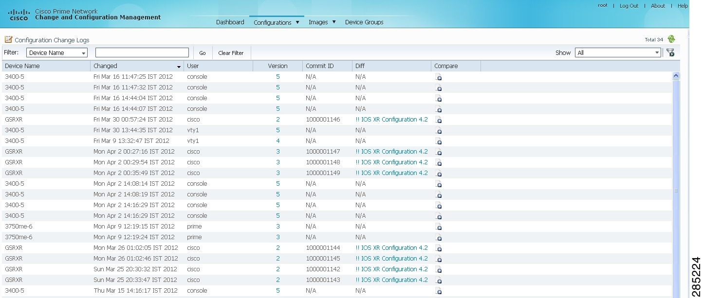
The Configuration Change Logs page displays change information, sorted according to the latest time stamp. (For a description of common fields, see Managing Device Configurations.) The date and time stamps are displayed according to the local time zone settings of the client.
You can view a maximum of 2000 records in the Configuration Change Logs page.
These fields are specific to the Configuration Change Logs page:
Making Sure Devices Conform to Policies Using Compliance Audit
Note![]() Starting in Prime Network 4.1, Compliance Audit replaces the Configuration Audit feature. In Prime Network 5.0, Configuration Audit is deprecated. However, if you enabled the option to retain Configuration Audit during an upgrade procedure from Prime Network 3.11 (or earlier), the feature will still be available from CCM.
Starting in Prime Network 4.1, Compliance Audit replaces the Configuration Audit feature. In Prime Network 5.0, Configuration Audit is deprecated. However, if you enabled the option to retain Configuration Audit during an upgrade procedure from Prime Network 3.11 (or earlier), the feature will still be available from CCM.
Compliance Audit ensures that existing device configurations comply to your deployment’s policies. Using Compliance Audit, you can create policies that can contain multiple rules, and policies can be grouped together to create a policy profile which can be run on a set of devices, called audit of devices. There is no limit on the number of policies, profiles, rules, and conditions that you can create using Compliance Audit.
There are 11 system-defined policy groups available in Compliance Audit. Each policy group comprises a set of system-defined policies. You can combine system-defined policies and user-defined policies to create a policy profile. But, you cannot edit, clone, or delete a system-defined policy group or a system-defined policy.
When CCM detects a violation, it can recommend a fix if one is configured by the administrator. Violation details are saved in the database for later reference.
In some scenarios, a fix may be readily available (as configured by the administrator) and can be directly applied, while in some others, the fix has to be carefully scrutinized by the administrator before it is run. Automatic application of some of the fixes can be disabled since it may conflict with other policies and configurations that may be specific to the device and the setup.
These topics explain how to use Compliance Audit:
- Wokrflow for Creating Policies and Profiles, and Running a Compliance Audit Job
- Creating a Policy
- Creating a Policy Profile
- Choosing the Devices for the Compliance Audit
- Viewing the Results of a Compliance Audit Job and Running Fixes for Violations
- Using Compliance Audit for Device Compliance
Wokrflow for Creating Policies and Profiles, and Running a Compliance Audit Job
Running an audit job the first time requires you to follow a specific workflow:
|
|
|
|
|---|---|---|
Viewing the Results of a Compliance Audit Job and Running Fixes for Violations |
Creating a Policy
Create a policy by choosing Compliance Audit > Compliance Policies. The Compliance Policy page (Figure 9-18) appears.
Figure 9-18 Compliance Policy Page
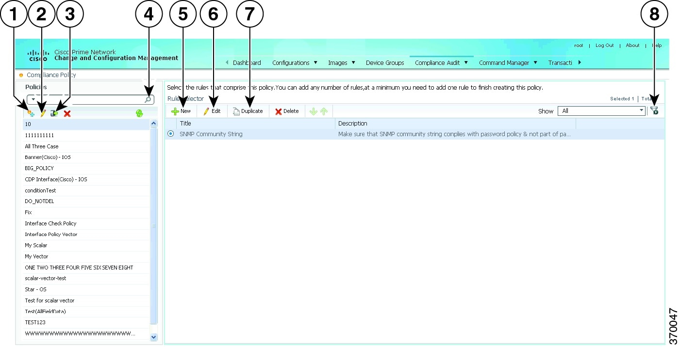
You can either create a new policy or you can import an existing policy by clicking the Import icon. You can export existing policies as XML files to your local drive.
Step 1![]() Click the Create Compliance Policy icon and enter the policy details. The policy is listed in the left pane.
Click the Create Compliance Policy icon and enter the policy details. The policy is listed in the left pane.
Step 2![]() From the Rule Selector pane, click New Rule icon. For more information on creating a new rule, see Creating a Rule.
From the Rule Selector pane, click New Rule icon. For more information on creating a new rule, see Creating a Rule.
Manage Advance Filters for a Compliance Audit
After you create a policy profile, you can create advanced filters with multiple filter criterion and save the filter setup as an Advanced Filter option. Whenever a compliance audit job is run, you can select the preset filters for the selected device and perform compliance audit as and when required, modify the filters to add a new device information, element types and so on and save the filter as a different query name. When the system job is run, you can export all configuration data irrespective of the last modification done on the archive.
For more information about Setting up Export device configuration and Periodic export parameters see, the Period Export options section in Table 9-1 and Managing Multilayer Quick Filters for Selected Devices in the Compliance Audit Jobs
Creating a Rule
For a policy to run against devices and generate violations, you must specify rules within the policy and define the conditions and the relevant fixes for violations. Rules are platform-specific. Each policy must contain at least one rule; however, there is no limitation on the number of rules you can define for a policy. You can also duplicate an existing rule and add to a policy. Click Duplicate to clone a rule. Follow the procedure below to create a rule and add the rule to a specific policy:
Step 1![]() From the left navigation pane, select the policy to which you want to add rules.
From the left navigation pane, select the policy to which you want to add rules.
Step 2![]() From the work area pane, click New.
From the work area pane, click New.
Step 3![]() Enter the following details. For sample rules, see Creating Rules—Samples.
Enter the following details. For sample rules, see Creating Rules—Samples.
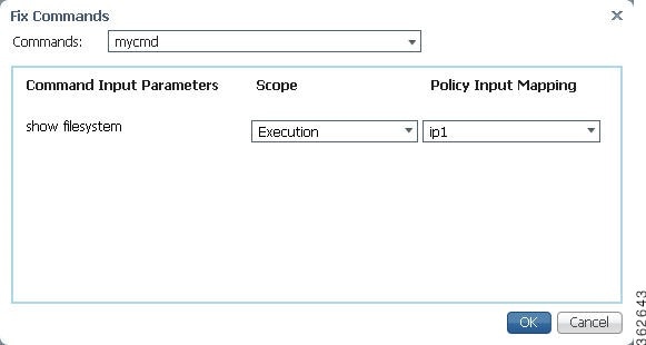
After you complete adding rules to the policy, a profile must be created. For more information, see Creating a Policy Profile.
Creating Rules—Samples
This section explains four scenarios in which rules can be created.
Problem This policy checks if at least one of the pre-defined DNS servers are configured on device.
The following condition checks if either IP name-server 1.2.3.4 or IP name-server 2.3.4.5 is configured on the device, and raises a violation if neither of them are configured.
Solution The following settings have to be made in the appropriate sections.
|
|
|
|---|---|
Problem This policy checks if at least two NTP servers are configured on the device for NTP server redundancy.
The following condition checks if the command ntp server appears at least twice.
Solution The following settings have to be made in the appropriate sections.
|
|
|
|---|---|
Problem This policy checks if the device is not configured with any prohibited community strings or community strings that must be avoided for SNMP.
This condition checks if either snmp-server community public or snmp-server community private is configured on the device. If configured, Compliance Audit raises a violation. Note that <1.1> in the violation text is replaced with the actual community string configured on the device, at the runtime. In this example, <1.1> indicates first captured group in the current condition.
Solution The following settings have to be made in the appropriate sections.
|
|
|
|---|---|
Problem This policy checks if a particular version of the IOS software is installed on a device.
The following condition checks if IOS software version 15.1(1)SY2 is installed on a device.
Solution The following settings have to be made in the appropriate sections.
|
|
|
|---|---|
Output of show version must contain the string ‘15.1(1)SY2’. |
Creating a Policy Profile
After you have created policies, create a policy profile that will contain a set of policies. Go to Compliance Audit > Policy Profile. The Policy Profile page (Figure 9-20) appears.
Figure 9-20 Policy Profile Page
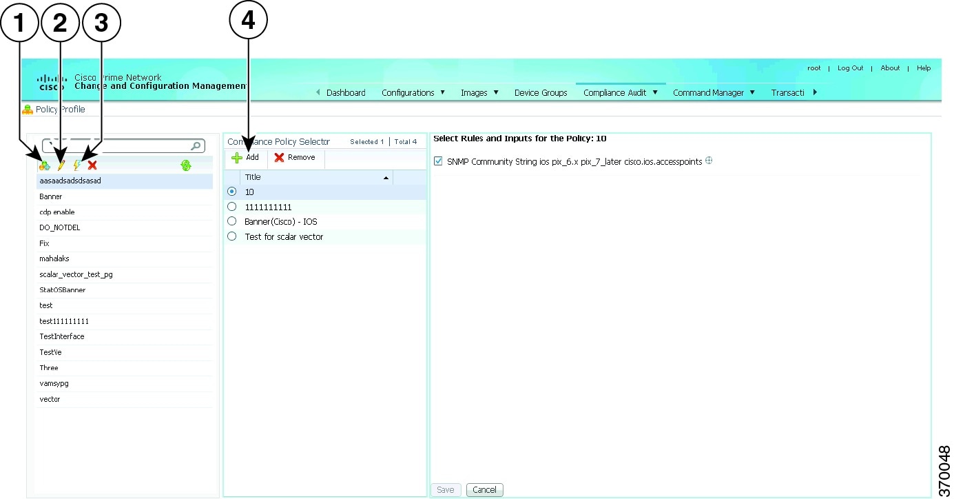
Follow the procedure below to create a new policy profile:
Step 1![]() From the left navigation pane, click the Create Policy Profile icon. Enter name and description of the policy profile.
From the left navigation pane, click the Create Policy Profile icon. Enter name and description of the policy profile.
Step 2![]() From the left navigation pane, select the policy profile that you have created. From the Compliance Policy Selector pane, click the Add Compliance Policy icon. The list of system-defined policy groups and user-defined policy group appear. See Table 9-4 for the list of policies grouped under each policy group.
From the left navigation pane, select the policy profile that you have created. From the Compliance Policy Selector pane, click the Add Compliance Policy icon. The list of system-defined policy groups and user-defined policy group appear. See Table 9-4 for the list of policies grouped under each policy group.
Step 3![]() Choose the required policies.
Choose the required policies.
Step 4![]() Select the rules and inputs within the selected policies, which you want to audit against. Later, if applicable, enter values for rule inputs. The option to enter rule inputs is available only if you have entered input parameters when you created a new rule. Policy Profiles are created and an audit job can be run.
Select the rules and inputs within the selected policies, which you want to audit against. Later, if applicable, enter values for rule inputs. The option to enter rule inputs is available only if you have entered input parameters when you created a new rule. Policy Profiles are created and an audit job can be run.
Choosing the Devices for the Compliance Audit
After you create a policy profile, you must choose the devices or device groups on which the compliance audit must be performed. After you choose the devices or device groups and schedule an audit, a job with the name of the policy profile is created. This name defines the job, and can be scheduled periodically. You can edit the job name.
Step 1![]() After you have created the profiles, click the Run Compliance Audit icon.
After you have created the profiles, click the Run Compliance Audit icon.
Step 2![]() In the Select Device window, choose one of the following options:
In the Select Device window, choose one of the following options:
- By Devices—Choose this option to select the device(s) that you want to audit. For more information about how to Manage advance filter options on r for the selected devices, see the Managing Multilayer Quick Filters for Selected Devices in the Compliance Audit Jobs.
- By Groups—Choose this option to select the device group(s) that you want to audit. There must be at least one device added to a device group for the group to be audited. If a device is added to multiple device groups that are selected for auditing, the device will be audited once. For information on how to set up a device group, see the “Setting Up CCM Device Groups” section.
Note![]() The audit will be performed on the devices that are available in the device group at the time of execution.
The audit will be performed on the devices that are available in the device group at the time of execution.
Step 4![]() In the Schedule Audit page, enter the schedule details. In the Choose Configuration option, select one of the following:
In the Schedule Audit page, enter the schedule details. In the Choose Configuration option, select one of the following:
- Use Latest Archived Configuration—If you choose this option, the latest Backup Configuration in the archive is used. If the backup configuration is not available, the device is not audited and is marked against non-audited devices.
- Use Current Device Configuration—If you choose this option, Prime Network polls for the latest configuration from the device and then performs the audit. If a Show command is used in the compliance policy, the output of the Show command is taken from the current device configuration.
- Use Send Audit Configuration Report—If you choose this option, a new compliance audit mail job is generated. The compliance audit mail job creates a new audit report and attaches the report as an excel sheet to the email with subject as Config Audit Report for Job ID:<id>. The excel sheet contains the details of device name, device IP, timestamp, the profile name, policy name, rule name, rule result, and violation message. You can cancel or delete the compliance audit mail job.
- Use Compare & Send Previous Configuration—If you choose this option, a new compliance audit mail job is generated with a message Compare & Send Previous Configuration will be performed from next job. From the next audit job, a new configuration comparison report is generated. If there are any changes between the earlier and the later audit reports, then the fields that have discrepancies appear in red. The configuration comparison report is attached to the email. You can cancel or delete the compliance audit mail job. You can also download the report as an excel sheet, for which you need to choose the devices and click Compare Previous Config in the Audited Devices window.
Step 5![]() Click Audit. An audit job is scheduled. You can view the status of an audit job from the Jobs page.
Click Audit. An audit job is scheduled. You can view the status of an audit job from the Jobs page.
Managing Multilayer Quick Filters for Selected Devices in the Compliance Audit Jobs
After choosing an option in the Select Devices area, use the multilayer advance filters to easily query device items. You can save preset filters for the selected device during a compliance audit, modify the filters to add or remove new device information, element types and so on, and save the filter again as a different name. When the system job is run, you can export all configuration data irrespective of the last modification done on the archive.
To create an Advanced Filter, follow the below steps:
1.![]() In the Policy Profile window, choose an profile and the click Run. The Compliance Audit window appears as shown in the figure 9-17.
In the Policy Profile window, choose an profile and the click Run. The Compliance Audit window appears as shown in the figure 9-17.

To Save the already created advanced filters. follow the below steps:
a.![]() From the Show drop-down list, choose Advanced Filter. If you want to set the criterion use the Match All of the following rules area. In the Filter fields, enter your criteria to view all the device details and then click Go.
From the Show drop-down list, choose Advanced Filter. If you want to set the criterion use the Match All of the following rules area. In the Filter fields, enter your criteria to view all the device details and then click Go.
Figure 9-22 Set Filter Criterion

b.![]() Select device names and then click the Save icon.
Select device names and then click the Save icon.

c.![]() In the Save a Preset filter dialog box, specify a name to the previously selected filter by devices and then click Save.
In the Save a Preset filter dialog box, specify a name to the previously selected filter by devices and then click Save.
Figure 9-24 Save a Preset Filter

d.![]() If the filter name already exists, a warning message appears as shown in the Figure 9-25
If the filter name already exists, a warning message appears as shown in the Figure 9-25

To modify, remove, or delete the preset advance filter:
a.![]() In the Edit Compliance Audit Job window, from the Show drop-down list, choose Manage Preset Filers to edit or remove the previously selected filters. The Manage a Preset Filter dialog box appears.
In the Edit Compliance Audit Job window, from the Show drop-down list, choose Manage Preset Filers to edit or remove the previously selected filters. The Manage a Preset Filter dialog box appears.
Figure 9-26 Manage Preset Filters

b.![]() From the Select a filter drop-down list, choose the relevant filter name to modify or remove the device information.
From the Select a filter drop-down list, choose the relevant filter name to modify or remove the device information.
c.![]() A prompt message for removal or deletion of the advance filter appears your confirmation.
A prompt message for removal or deletion of the advance filter appears your confirmation.
Figure 9-27 A Delete Prompt Message

d.![]() Click OK to continue for any modification or deletion.
Click OK to continue for any modification or deletion.
e.![]() After modification click the Save icon to save in a different name. If the filter name already exists, a warning message appears as shown in the figure Figure 9-28.
After modification click the Save icon to save in a different name. If the filter name already exists, a warning message appears as shown in the figure Figure 9-28.
Figure 9-28 Overwrite the filter

Viewing the Results of a Compliance Audit Job and Running Fixes for Violations
The status of scheduled jobs appears on the Jobs page (Compliance Audit > Jobs). All audits are logged by Prime Network as jobs.
From this page, you can view the violation details and can also apply a fix. To apply a fix for a violation, you can either do a regular fix or use a predefined command that is available in the Command Manager. After a job is created, you can set the following preferences for the job:
- Suspend—Can be applied only on jobs that are scheduled for future. You cannot suspend a job that is running.
- Resume—Can be applied only on jobs that have been suspended.
- Reschedule—Using this option, you can reschedule a job that has been scheduled for a different time. Choose a job, and click Reschedule. The Compliance Audit Job Rescheduler window opens. Set your preferences. The following options are available against Choose Configuration option:
–![]() Use Latest Archived Configuration—If you choose this option, the latest Backup Configuration in the archive is used. If Show command is used in the compliance policy, the output of the Show command is taken from the current device configurations.
Use Latest Archived Configuration—If you choose this option, the latest Backup Configuration in the archive is used. If Show command is used in the compliance policy, the output of the Show command is taken from the current device configurations.
–![]() Use Latest Configuration from Device—If you choose this option, Prime Network polls for the latest configuration from the device and performs the audit.
Use Latest Configuration from Device—If you choose this option, Prime Network polls for the latest configuration from the device and performs the audit.
Note![]() You might be prompted to enter your device access credentials. This option is enabled if, from the Administration client, Global Settings > Security Settings > User Account Settings > Execution of Configuration Operations, you checked the option Ask for user credentials when running configuration operations. This is an enhanced security measure to restrict access to devices.
You might be prompted to enter your device access credentials. This option is enabled if, from the Administration client, Global Settings > Security Settings > User Account Settings > Execution of Configuration Operations, you checked the option Ask for user credentials when running configuration operations. This is an enhanced security measure to restrict access to devices.
- Cancel—Using this option, you can cancel a scheduled job or the job that is in the running state. Once the job is canceled, the job status with Canceled status appears against the Last Run Status field. Click the Canceled hyperlink to view the user who has canceled that job.
- View—This option is enabled only for jobs that are in Completed state. Using this option, you can view the details of a job, the associated policies and devices. If you have selected a device group for auditing, click the hyperlinked device group name to display the list of devices included in the device group.
- Edit—Using this option, you can edit a scheduled job. You cannot edit a job that is running. If you have selected By Groups in the Select Device page when scheduling an audit, you cannot select By Devices, and vice versa, when editing the scheduled job.
- Delete—This option deletes a job that has been scheduled. This deletes the listing from CCM. You cannot delete a job that is running.
All jobs that are completed are listed in the jobs page. The job is flagged a success only if all the devices audited conform to the policies specified in the profile. The result, otherwise, is displayed as Failure. The job is called a partial success if job contains a mix of both audited and non-audited devices, with the compliance status of audited devices being a success.
Export Job Results
You can view the Job status in a XLS format for the completed job from the All Jobs tab, or from each module of the CCM. You can view the export option only for the following selected job types from the CCM module.
|
|
|
|---|---|
Archives, which includes Backup, Restore, Synchronize and so on |
|
Import; from device, Package add, Distribution, Activation, Commit, Rollback |
|
To export and view the job results in XLS format from Change and Configuration:
Step 1![]() Log in to the Change and Configuration Management client.
Log in to the Change and Configuration Management client.
Step 2![]() Click the All Jobs tab.
Click the All Jobs tab.
Step 3![]() Select a row that has a Job type that is mentioned above. Ensure that the Job Status is in Scheduled or Completed and the Lastrun Status is Success or Partial_Success for a selected job type.
Select a row that has a Job type that is mentioned above. Ensure that the Job Status is in Scheduled or Completed and the Lastrun Status is Success or Partial_Success for a selected job type.
For example, when you click the Lastrunresult of a compliance audit job type, the Compliance Job Audit Details window displays the compliance audit and violation details. For more information about audit violation details, see Job Details and Violations Summary.
Step 4![]() Click the hyperlinked Lastrunresult displayed against each job to view the details of a specific job.
Click the hyperlinked Lastrunresult displayed against each job to view the details of a specific job.
Step 5![]() In the Job Details window, click Export Result to export the job results in a XLS format.
In the Job Details window, click Export Result to export the job results in a XLS format.
Note![]() Job status details can be exported and downloaded from the other CCM module’s Job page.
Job status details can be exported and downloaded from the other CCM module’s Job page.
Step 6![]() Click OK to close a specific Job Details window.
Click OK to close a specific Job Details window.
Job Details and Violations Summary
Figure 9-29 displays the information about the available and selected devices, rules that you selected for the compliance audit, compliance state, violation count, instance count, highest severity and ignore count. The information about audited devices from all the devices are displayed separately at the back end.
Figure 9-29 Job Details and Violations Summary
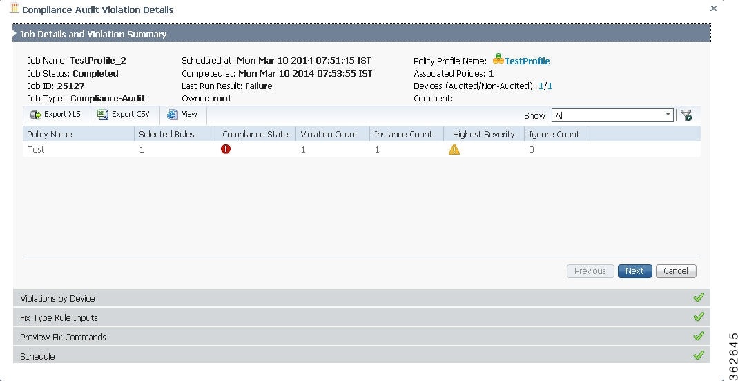
Figure 9-30 displays the violations at a device level.
Figure 9-30 Violations by Device
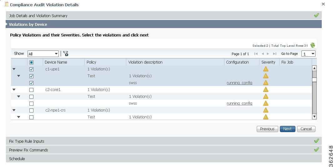
Select the devices that require the fix CLI to be applied. The check box for a device will be enabled when:
- a fix CLI is available for the device.
- the violation is not fixed on the device.
- no fix job is running for the violation.
Click the running config link under the Configurations column to view the running configurations of the device. If a Show command is used in the compliance policy, the output of the Show command is also displayed.
If a violation has already been fixed or a fix job has been scheduled, the Fix Job column displays the name of the fix job with a hyperlink. Click the hyperlink to view the compliance fix details. The check box for that violation will be disabled.
This window is applicable only if you have a fix type input for the violation. Enter the required rule input to fix the violation. Click Next. See Figure 9-31.
Figure 9-31 Fix Type Rule Input
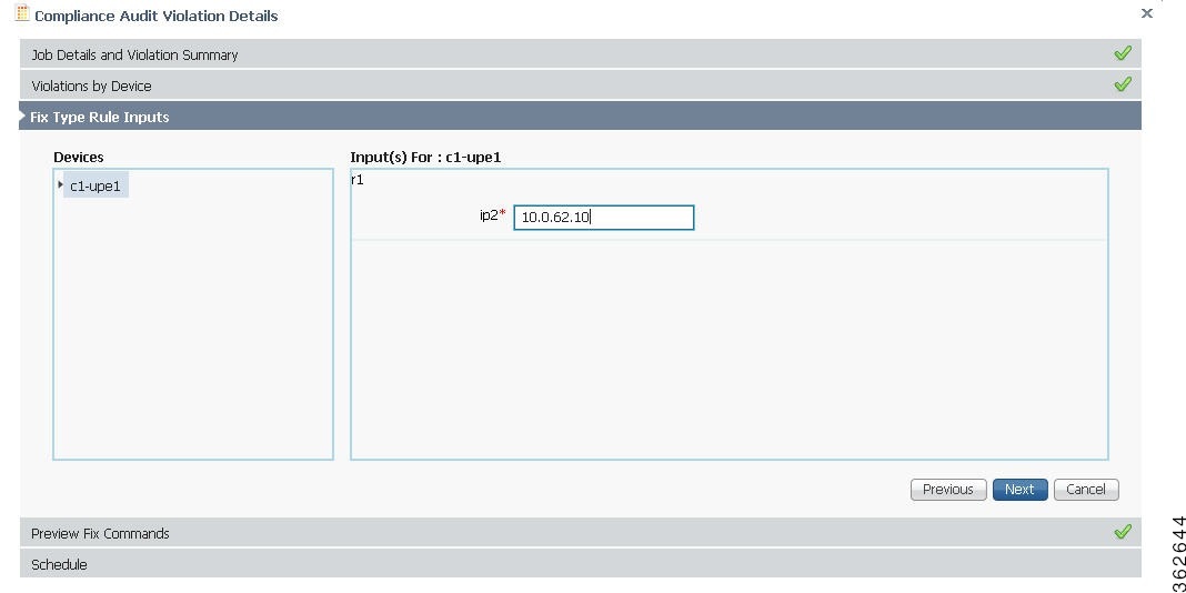
Figure 9-32 displays the preview of the fix CLI that will be applied to the device when you schedule a fix job. If you are using the predefined command that is available in the Command Manager to fix the violation, the command builder script name with a hyperlink is displayed. Click the hyperlink to view the values that will be executed on the device to fix the compliance violation. Click Next.
Figure 9-32 Preview Fix Commands
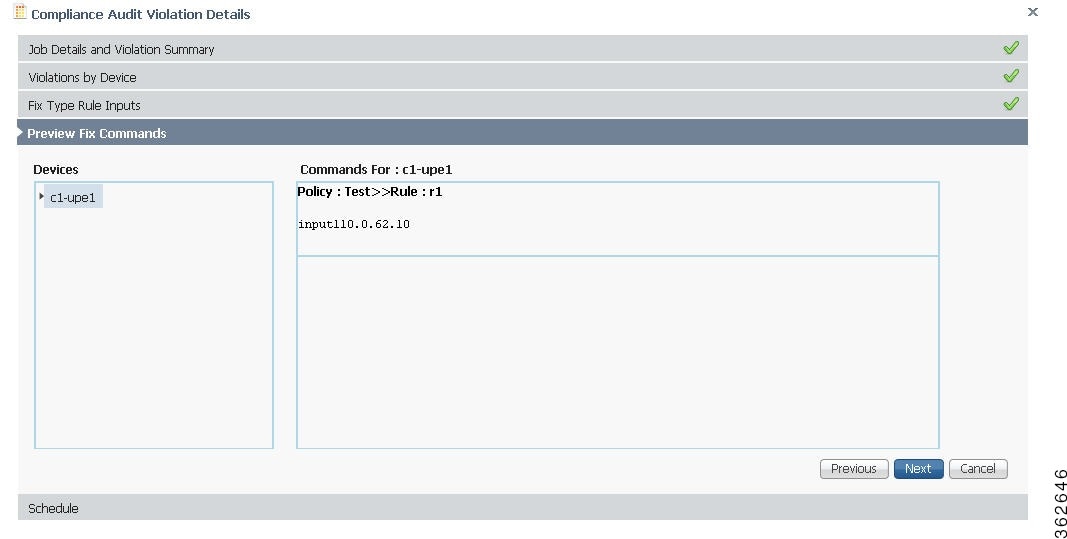
Set the scheduling options such as the job name, start time, and email ID. Click Fix Job to schedule the job. The details of the fix job can be viewed from Compliance Audit > Jobs. The job type is Compliance-Fix. See Figure 9-33.
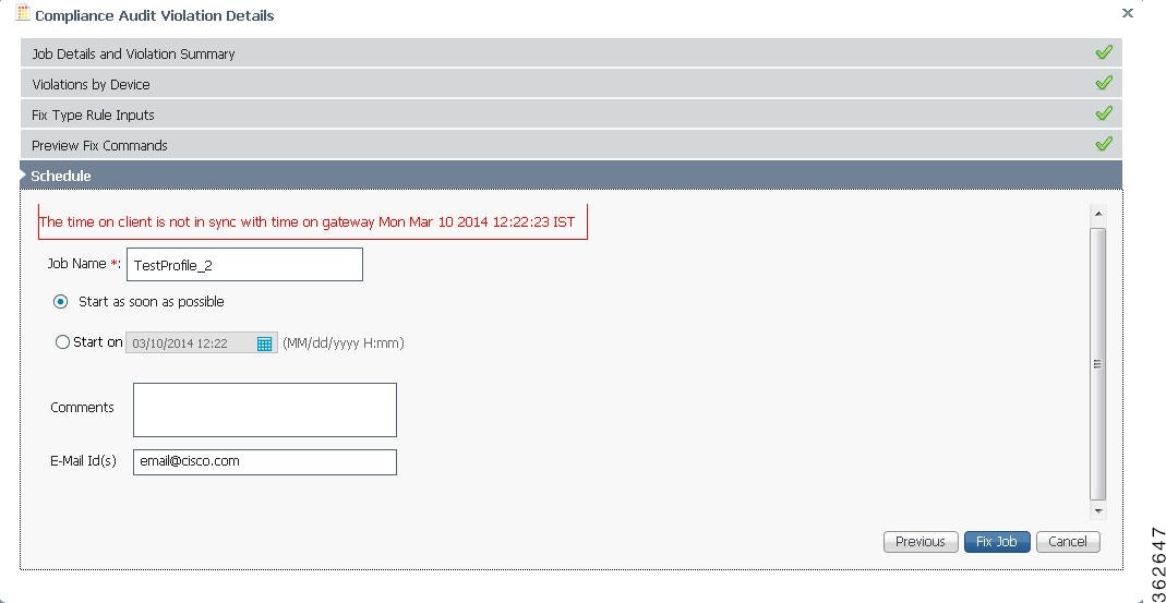
You can view the status of a fix job after the job completes. Click the hyperlinked status to view the results of the fix job.
Using Compliance Audit for Device Compliance
Note![]() Starting in Prime Network 4.1, Configuration Audit is being replaced by Compliance Audit. In Prime Network 5.0, Configuration Audit is deprecated. However, if you enabled the option to retain Configuration Audit during an upgrade procedure from Prime Network 3.11 (or earlier), the feature will still available from CCM. For more information on Compliance Audit, see Making Sure Devices Conform to Policies Using Compliance Audit.
Starting in Prime Network 4.1, Configuration Audit is being replaced by Compliance Audit. In Prime Network 5.0, Configuration Audit is deprecated. However, if you enabled the option to retain Configuration Audit during an upgrade procedure from Prime Network 3.11 (or earlier), the feature will still available from CCM. For more information on Compliance Audit, see Making Sure Devices Conform to Policies Using Compliance Audit.
These topics describe how to use Compliance Audit:
- Managing Compliance Audit Policies
- Scheduling a Compliance Audit
- Viewing Compliance Audit Jobs and Audit Results
The CCM Compliance Audit feature checks device compliance to ensure they comply to a compliance policy file (the baseline or expected configuration). Each compliance policy is a set of CLI commands that define a desired baseline or expected configuration. Compliance policies can also be configured using valid, Java-based regular expressions. Table 9-7 provides examples of compliance policy CLIs.
The following example shows a policy that performs audit for BGP configuration for a Cisco IOS router:
If you want an audit check for specific BGP AS or neighbor IP address, the above CLI can be changed accordingly. For example:
You can combine multiple different configurations into one policy. For example:
Compliance audit can be scheduled against multiple configuration files to obtain an audit report that indicates the existence of configuration sequences stated in the baseline policy and any deviations from the baseline.
You can define a compliance policy, create and save the advance filters and select the devices that need to be audited against the policy, and schedule the audit job to run immediately or at a later point in time. The audit job compares the CLI commands (as part of the configuration policy) against the actual running configuration on the device to identify the discrepancies.
You can view the status of all the scheduled compliance audit jobs in the Job Manager page. The compliance audit results are in the form of a report indicating the discrepancies (missing configuration commands on the device) in red and the matching commands in green.
Managing Compliance Audit Policies
CCM allows you to create, modify, view, and delete configuration policies. Choose Compliance Audit > Compliance Policies. The Configuration Policies page provides the list of existing policies. You can search the configuration policies by CLI strings.
Creating a Compliance Policy
To create a compliance policy:
Step 1![]() In the Configuration Policies page, click the Create icon.
In the Configuration Policies page, click the Create icon.
Step 2![]() Provide the policy name and description.
Provide the policy name and description.
Step 3![]() Enter the CLI commands to set up a baseline configuration for that policy. This can also be a valid, Java-based regular expression. See Table 9-7 for sample configuration CLIs.
Enter the CLI commands to set up a baseline configuration for that policy. This can also be a valid, Java-based regular expression. See Table 9-7 for sample configuration CLIs.
Step 4![]() Make sure you follow the guide 5.0 while entering the CLI commands. Click Guide5.0 to view these guide5.0 as shown in Figure 9-34.
Make sure you follow the guide 5.0 while entering the CLI commands. Click Guide5.0 to view these guide5.0 as shown in Figure 9-34.
Figure 9-34 Create Configuration Policy-Showing Guide5.0
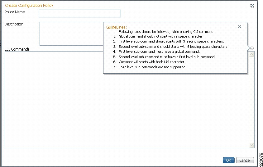
Editing, Viewing, and Deleting Compliance Policy
In the Compliance Policies page, you can also do the following:
- Select a policy and click Edit to modify the policy description and CLI commands. You cannot modify the policy name. Keep in mind the policy guide 5.0 while modifying the CLI commands.
- Select a policy and click View to view the policy name, description, and CLI commands.
- Select a policy or multiple policies and click Delete to delete the configuration policies. You cannot delete a policy if it is part of a scheduled audit job.
Scheduling a Compliance Audit
You can schedule compliance audit jobs to run immediately or at a later point in time.
Note![]() Only a maximum of 10 policies and 500 devices can be used for scheduling an audit job.
Only a maximum of 10 policies and 500 devices can be used for scheduling an audit job.
To schedule a compliance audit job:
Step 1![]() Choose Compliance Audit > Basic Audit. The Select Configuration Policies page lists the available configuration policies. You can search the configuration policies by using CLI strings.
Choose Compliance Audit > Basic Audit. The Select Configuration Policies page lists the available configuration policies. You can search the configuration policies by using CLI strings.
Step 2![]() Select the desired configuration policy from the available list and click Next.
Select the desired configuration policy from the available list and click Next.
Step 3![]() In the Select Devices page, select the devices that must be audited against the selected configuration policy, and then click Next.
In the Select Devices page, select the devices that must be audited against the selected configuration policy, and then click Next.
Step 4![]() Under the Match the following Rule area, enter the filter details and click the Plus icon to save as a preset filter.
Under the Match the following Rule area, enter the filter details and click the Plus icon to save as a preset filter.
Step 6![]() In the Schedule Audit page, provide a job name and the scheduling information for the compliance audit job. You can choose to run the audit job immediately or at a later point in time. A popup with the gateway time is available to assist you in setting up the time for scheduling the audit job.
In the Schedule Audit page, provide a job name and the scheduling information for the compliance audit job. You can choose to run the audit job immediately or at a later point in time. A popup with the gateway time is available to assist you in setting up the time for scheduling the audit job.
Step 7![]() Click Audit. You will be redirected to the Compliance Audit Jobs page.
Click Audit. You will be redirected to the Compliance Audit Jobs page.
Note![]() Once scheduled, you cannot edit the policies or devices that are part of the scheduled job.
Once scheduled, you cannot edit the policies or devices that are part of the scheduled job.
Viewing Compliance Audit Jobs and Audit Results
The Compliance Audit Jobs page (Compliance Audit > Compliance Audit Jobs) provides the following details:
- Jobs—This table lists all compliance audit jobs submitted by the login user. The ‘root’ user can view jobs submitted by other users, by selecting the username from the table header.
- History—For a selected job in the Jobs table, this table lists all the instances. You can select only one job at a time to view the history details.
You can select a job and click View to view the associated devices and policies, and the schedule for the selected audit job.
You can also use this page to suspend, resume, cancel, delete, or reschedule a job.
To view the compliance audit job details and the audit result:
Step 1![]() Click the hyperlinked LastRun Result (Success/Partial Success/Failure) against a particular job in the Jobs table.
Click the hyperlinked LastRun Result (Success/Partial Success/Failure) against a particular job in the Jobs table.
The Compliance Audit Job Details dialog box displays the job details and the audit results for a device and policy combination, as shown in Figure 9-35. The Job Results table includes the device audited, policy against which the device was audited, audit status, and the running configuration version used for the audit. A blue tick mark in the Status column indicates ‘Audit Pass’, and a red X indicates ‘Audit Fail’. Click the hyperlinked policy name to view the configuration policy details, with updates if the policy has been modified.
Note![]() For Cisco Nexus devices, the VDC name is also displayed in the Device Name column.
For Cisco Nexus devices, the VDC name is also displayed in the Device Name column.
Figure 9-35 Compliance Audit Job Details
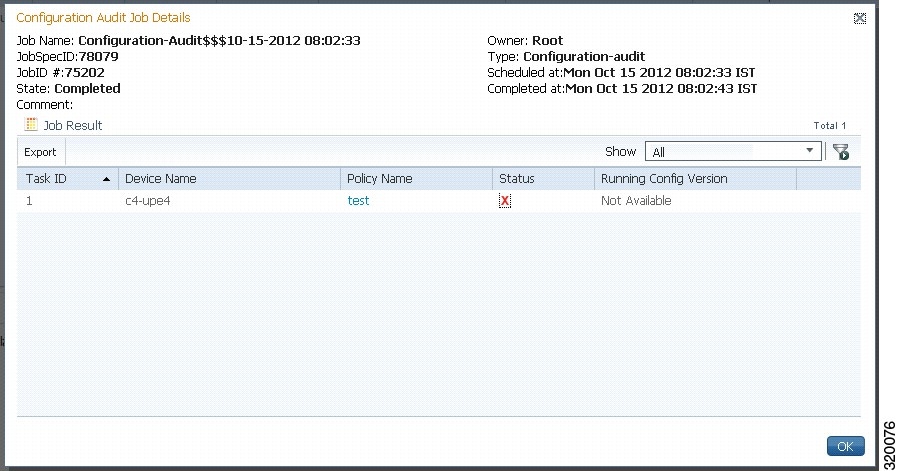
Step 2![]() Click on the hyperlinked Status (Pass/Fail icon) in the Job Results table. Or, click the hyperlinked Success or Failure hyperlink in the Result field of the History table. The Compliance Audit Result dialog box displays the audit result with matching commands (for ‘Audit Pass’) and discrepancies or missing commands (for ‘Audit Fail’) between the policy and the running configuration on the device. See Figure 9-36 for an example of the Compliance Audit Result dialog box for an ‘Audit Fail’ scenario.
Click on the hyperlinked Status (Pass/Fail icon) in the Job Results table. Or, click the hyperlinked Success or Failure hyperlink in the Result field of the History table. The Compliance Audit Result dialog box displays the audit result with matching commands (for ‘Audit Pass’) and discrepancies or missing commands (for ‘Audit Fail’) between the policy and the running configuration on the device. See Figure 9-36 for an example of the Compliance Audit Result dialog box for an ‘Audit Fail’ scenario.
Figure 9-36 Compliance Audit Result - Audit Fail
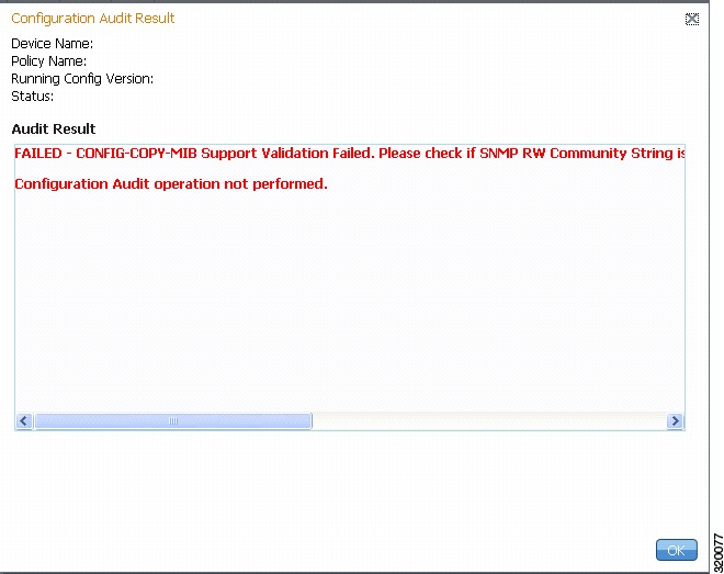
The matching commands are displayed in green (see Figure 9-37), while the discrepancies are displayed in red (see Figure 9-36). For a failed job, the Audit Result section also displays the reason why the audit was not successful as shown in Figure 9-36. Some reasons for audit failure are:
Figure 9-37 Compliance Audit Result - Audit Pass
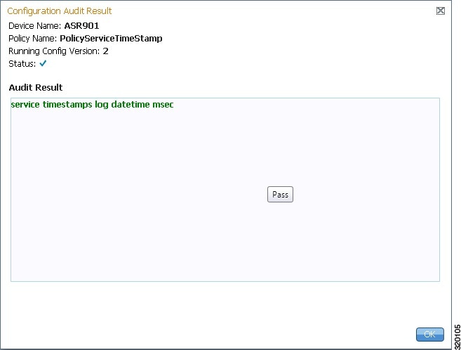
Step 3![]() Click Export in the Job Results table to export the audit job results to a.csv file. You can view the job details and audit results in the exported file.
Click Export in the Job Results table to export the audit job results to a.csv file. You can view the job details and audit results in the exported file.
Checking Image Management, Device Management, and Compliance Audit Jobs
When a job is created, Prime Network assigns it a job specification ID and attaches a time stamp, indicating when the job was created. Only the job creator and users with Administrator privileges can change the job settings.
Note![]() Whenever a CCM job is scheduled to run immediately, you will be prompted, either to stay in the same page or to be redirected to the Jobs page.
Whenever a CCM job is scheduled to run immediately, you will be prompted, either to stay in the same page or to be redirected to the Jobs page.
CCM also facilitates automatic e-mail notification of the status of the CCM jobs upon completion based on the e-mail option you set up in the Image Management Settings page. The notification is sent to a list of e-mail IDs configured either in the settings page or while scheduling the job.
Keep these items in mind when managing jobs:
- All jobs are scheduled based on the gateway time.
- If you choose two or more jobs and click Reschedule, the option defaults to Start as Soon as Possible. To view the original time and then reschedule, choose only one job and click Reschedule.
- Job properties cannot be edited; you must delete the old job and create a new one.
- Jobs are persisted even if the gateway server is restarted.
- Only the job creators and users with Administrator and Configurator privileges can perform the actions provided on the Jobs page (suspend, resume, reschedule, cancel, delete, refresh).
- Configuration and CCM jobs fail under the following conditions:
–![]() If the device is not under the scope of the user to perform the config or image operation.
If the device is not under the scope of the user to perform the config or image operation.
–![]() If the user is not authorized to perform the config or image operation.
If the user is not authorized to perform the config or image operation.
- Running jobs cannot be suspended or canceled; you must let them complete.
- System-generated jobs cannot be modified. To change the settings, go to Settings > Global Settings > Period Export Options, and modify the options accordingly.
- Cancel stops all future instances of a job. To stop a job and resume it later, use Suspend and Resume
- To view the history of a job, choose a job and view the history from the History tab at the bottom of the page. You cannot view history of multiple jobs at the same time; choose only one job at a time.
Messages that can be used for debugging are saved in NETWORKHOME /XMP_Platform/logs/JobManager.log.
 Feedback