- About This Book
-
- Getting Started
- Setting Up the Prime Fulfillment Services for L2VPN
- Creating a FlexUNI/EVC Ethernet Policy
- Creating a FlexUNI/EVC Ethernet Service Request
- Creating a FlexUNI/EVC ATM-Ethernet Interworking Policy
- Creating a FlexUNI/EVC ATM-Ethernet Interworking Service Request
- Creating an L2VPN Policy
- Creating an L2VPN Service Request
- Creating a VPLS Policy
- Creating a VPLS Service Request
- Deploying, Monitoring, and Auditing Service Requests
- Using Auto Discovery for L2 Services
- Sample Configlets
- Setting Up VLAN Translation
-
- Getting Started with MPLS VPN
- Setting Up the Prime Fulfillment Services
- Independent VRF Management
- IPv6 and 6VPE Support in MPLS VPN
- MPLS VPN Service Policies
- MPLS VPN Service Requests
- Provisioning Regular PE-CE Links
- Provisioning Multi-VRFCE PE-CE Links
- Provisioning Management VPN
- Provisioning Cable Services
- Provisioning Carrier Supporting Carrier
- Provisioning Multiple Devices
- Spanning Multiple Autonomous Systems
- Sample Configlets
- Troubleshooting MPLS VPNs
Cisco Prime Fulfillment User Guide 6.1
Bias-Free Language
The documentation set for this product strives to use bias-free language. For the purposes of this documentation set, bias-free is defined as language that does not imply discrimination based on age, disability, gender, racial identity, ethnic identity, sexual orientation, socioeconomic status, and intersectionality. Exceptions may be present in the documentation due to language that is hardcoded in the user interfaces of the product software, language used based on RFP documentation, or language that is used by a referenced third-party product. Learn more about how Cisco is using Inclusive Language.
- Updated:
- March 20, 2015
Chapter: Setting Up the Prime Fulfillment Services
Setting Up the Cisco Prime Fulfillment Services
This chapter contains the basic steps to set up the Prime Fulfillment services to support MPLS VPN service policies and service requests.

Note ![]() This chapter presents high-level information on Prime Fulfillment services that are relevant to MPLS VPN. For more detailed information on setting up these and other basic Prime Fulfillment services, see the Setting Up Services and Managing Service Requests parts. .
This chapter presents high-level information on Prime Fulfillment services that are relevant to MPLS VPN. For more detailed information on setting up these and other basic Prime Fulfillment services, see the Setting Up Services and Managing Service Requests parts. .
Overview
To create an MPLS VPN service request, you must create the following infrastructure data:
•![]() Devices
Devices
A Device in Prime Fulfillment is a logical representation of a physical device in the network. You can import devices (configurations) into Prime Fulfillment by using Inventory Manager or the Prime Fulfillment GUI. You can also use the Auto Discovery feature of Inventory Manager to import devices into the Repository.
•![]() Customers
Customers
A customer is typically an enterprise or large corporation that receives network services from a service provider. A Customer is also a key logical component of Prime Fulfillment.
–![]() Sites
Sites
A Site is a logical component of Prime Fulfillment that connects a Customer with a CE. It can also represent a physical customer site.
–![]() CPE/CE Devices
CPE/CE Devices
A CPE is "customer premises equipment," typically a customer edge router (CE). It is also a logical component of Prime Fulfillment. You can create CPE in Prime Fulfillment by associating a device with a Customer Site.
•![]() Providers
Providers
A provider is typically a "service provider" or large corporation that provides network services to a customer. A Provider is also a key logical component of Prime Fulfillment.
–![]() Regions
Regions
A Region is a logical component of Prime Fulfillment that connects a Provider with a PE. It can also represent a physical provider region.
–![]() PE Devices
PE Devices
A PE is a provider edge router or switch. It is also a logical component of Prime Fulfillment. You can create PE in Prime Fulfillment by associating a Device with a Provider Region. In Prime Fulfillment, a PE can be a "point of presence" router (POP) or a Layer 2 switch (CLE).
•![]() Access Domains (for Layer 2 Access)
Access Domains (for Layer 2 Access)
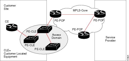
The Layer 2 Ethernet switching domain that connects a PE to a CE is called an Access Domain. All the switches attached to the PE-POP belong to this Access Domain. These switches belong to the Provider and are defined in Prime Fulfillment as PE-CLE.
•![]() Resource Pools
Resource Pools
–![]() IP Addresses
IP Addresses
–![]() Multicast
Multicast
–![]() Route Distinguisher
Route Distinguisher
–![]() Route Target
Route Target
–![]() VLANs (for Layer 2 Access)
VLANs (for Layer 2 Access)
•![]() VPN
VPN
Before creating a Service Policy, a VPN name must be defined within Prime Fulfillment.
•![]() Route Target(s)
Route Target(s)
Creating Devices
This section describes how to create a Device with the Prime Fulfillment GUI, connect to a Cisco IOS router in the network, collect the live configuration, and populate the Repository.
Creating Logical Devices
To create a logical device, perform the following steps.
Step 1 ![]() Choose Inventory > Physical Inventory > Devices.
Choose Inventory > Physical Inventory > Devices.
The Devices Inventory window appears.
Step 2 ![]() Click Create.
Click Create.
Step 3 ![]() From the drop-down list, choose Cisco Device.
From the drop-down list, choose Cisco Device.
The Create Cisco Router window appears, as shown in Figure 21-1.
Figure 21-1 New Device Information
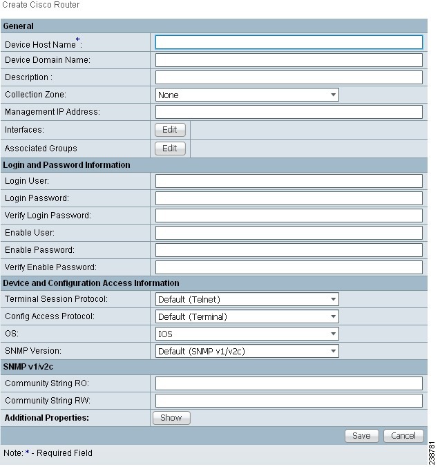
Step 4 ![]() Enter all required information for this new device.
Enter all required information for this new device.
Step 5 ![]() For Additional Properties, click Show.
For Additional Properties, click Show.
Step 6 ![]() To save this new device, click Save.
To save this new device, click Save.
You have saved a Device in the Repository.
Collecting Configurations
This section describes how to connect to the physical device in the network, collect the device information from the router, and populate the Repository. To do this, perform the following steps.
Step 1 ![]() Choose Operate > Tasks > Task Manager.
Choose Operate > Tasks > Task Manager.
The Task Manager window appears.
Step 2 ![]() Click Create.
Click Create.
Step 3 ![]() Choose Collect Config.
Choose Collect Config.
The Create Task window appears.

Tip ![]() You might want to change the default Name and Description for this task, so you can more easily identify it in the task log.
You might want to change the default Name and Description for this task, so you can more easily identify it in the task log.
Step 4 ![]() Click Next.
Click Next.
The Collect Config Task window appears, as shown in Figure 21-2.
Figure 21-2 Collect Config Task
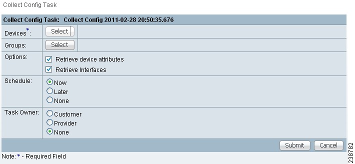
Step 5 ![]() To choose devices associated to the task, in the Devices panel, click Select.
To choose devices associated to the task, in the Devices panel, click Select.
The Select Device window appears.
Step 6 ![]() Check to choose the desired device(s), then click Select.
Check to choose the desired device(s), then click Select.
The Collect Config Task window reappears.
Step 7 ![]() To choose device groups associated to the task, in the Groups panel, click Select.
To choose device groups associated to the task, in the Groups panel, click Select.
A list of available device groups appears.
Step 8 ![]() Check to choose the desired device group(s), then click Select.
Check to choose the desired device group(s), then click Select.
The Collect Config Task window reappears.
Step 9 ![]() Set schedule and task owner, if applicable.
Set schedule and task owner, if applicable.
Step 10 ![]() Click Submit.
Click Submit.
The Tasks window appears.
Step 11 ![]() Choose your task in the Task Name column, then click Details to view more information.
Choose your task in the Task Name column, then click Details to view more information.
Monitoring Task Logs
To monitor task logs, perform the following steps.
Step 1 ![]() Choose Operate > Tasks > Task Manager.
Choose Operate > Tasks > Task Manager.
The Tasks Manager window appears.
Step 2 ![]() In the Selection pane, click Logs.
In the Selection pane, click Logs.
The Task Runtime Actions window appears.
Note ![]() The Status field shows the task has completed successfully.
The Status field shows the task has completed successfully.
Step 3 ![]() Choose your task and then click Instances to view more information.
Choose your task and then click Instances to view more information.
Creating Device Groups
To create device groups, perform the following steps.
Step 1 ![]() Choose Inventory > Physical Inventory > Device Groups.
Choose Inventory > Physical Inventory > Device Groups.
The Device Groups Inventory window appears.
Step 2 ![]() Click Create.
Click Create.
The Create New Device Group window appears.
Step 3 ![]() In the Device Group Name field, enter the device group name.
In the Device Group Name field, enter the device group name.
Step 4 ![]() Click Save.
Click Save.
Setting Up Devices for IOS XR Support
Prime Fulfillment supports provisioning of basic MPLS VPNs on devices running Cisco's IOS XR software. IOS XR, a new member of the Cisco IOS family, is a unique self-healing and self-defending operating system designed for always-on operation while scaling system capacity up to 92Tbps.
Note ![]() For information about specific platforms and features supported for IOS XR devices for MPLS VPN, as well as IOS XR versions supported, see the Release Notes for Cisco Prime Fulfillment 6.1.
For information about specific platforms and features supported for IOS XR devices for MPLS VPN, as well as IOS XR versions supported, see the Release Notes for Cisco Prime Fulfillment 6.1.
To enable IOS XR support in MPLS VPN, perform the following steps.
Step 1 ![]() Set the DCPL property Provisioning/Service/mpls/platform/CISCO_ROUTER/IosXRConfigType to XML.
Set the DCPL property Provisioning/Service/mpls/platform/CISCO_ROUTER/IosXRConfigType to XML.
Possible values are CLI, CLI_XML, and XML (the default).
Step 2 ![]() Set the DCPL property DCS/getCommitCLIConfigAfterDownload to true (the default).
Set the DCPL property DCS/getCommitCLIConfigAfterDownload to true (the default).
This allows Prime Fulfillment to retrieve the committed CLI configuration after an XML configuration has been downloaded. See Chapter 47, "Viewing Configlets on IOS XR Devices" for more information.
Step 3 ![]() Create the device in Prime Fulfillment as an IOS XR device, as follows:
Create the device in Prime Fulfillment as an IOS XR device, as follows:
a. ![]() Create the Cisco device by choosing Inventory > Physical Inventory > Devices > Create.
Create the Cisco device by choosing Inventory > Physical Inventory > Devices > Create.
The Create Cisco Device window appears.
b. ![]() Set the OS attribute, located under Device and Configuration Access Information, to IOS_XR.
Set the OS attribute, located under Device and Configuration Access Information, to IOS_XR.
Note ![]() For additional information on setting DCPL properties and creating Cisco devices, see the Appendix B, "Property Settings".
For additional information on setting DCPL properties and creating Cisco devices, see the Appendix B, "Property Settings".
Step 4 ![]() Create and deploy MPLS VPN service requests, following the procedures in this guide.
Create and deploy MPLS VPN service requests, following the procedures in this guide.
Sample configlets for IOS XR devices are provided in Chapter 33, "Sample Configlets".
Migrating PE Devices from IOS to IOS XR
For information on migrating PE devices from IOS to IOS XR, see Migrating PE Devices from IOS to IOS XR, page 25-29.
Creating Customers, Sites, and CPEs
In Prime Fulfillment, a customer is defined by the following three logical components:
•![]() Customer Name
Customer Name
•![]() Customer Site
Customer Site
•![]() Customer Device (CPE)
Customer Device (CPE)
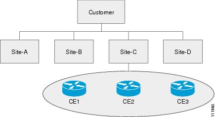
In Prime Fulfillment, a Customer is a logical container for Sites and CEs.
Within a Customer, there can be one or more Sites. Sites are logical entities that can be defined in any way that makes sense to a service provider.
Figure 21-3 shows an overview of an Prime Fulfillment Customer.
Figure 21-3 Overview of an Prime Fulfillment Customer
This section describes how to create a Customer with the Prime Fulfillment GUI, create a Site for the Customer, and associate a Device with the Site. This section covers the following topics:
Creating Customers
To create a customer, perform the following steps.
Step 1 ![]() Choose Service Design > Resources > Customers.
Choose Service Design > Resources > Customers.
The Customers window appears.
Step 2 ![]() Click Create.
Click Create.
The Create New Customer window appears.
Step 3 ![]() Enter a customer name and then click Save.
Enter a customer name and then click Save.
The Customers window appears.
Creating Sites
To create a site, perform the following steps.
Step 1 ![]() Choose Inventory > Resources > Customer Sites.
Choose Inventory > Resources > Customer Sites.
The Customer Sites window appears.
Step 2 ![]() Click Create.
Click Create.
Step 3 ![]() Enter a site name in the Name field.
Enter a site name in the Name field.
Step 4 ![]() To associate a customer to this site, in the Customer field, click Select.
To associate a customer to this site, in the Customer field, click Select.
A list of available customer names appears.
Step 5 ![]() Check to choose the desired customer, then click Select.
Check to choose the desired customer, then click Select.
Step 6 ![]() Click Save.
Click Save.
Creating CPEs
To create a CPE device, perform the following steps.
Step 1 ![]() Choose Inventory > Resources > Customer Devices.
Choose Inventory > Resources > Customer Devices.
Step 2 ![]() Click Create.
Click Create.
Step 3 ![]() In the Device Name field, click Select.
In the Device Name field, click Select.
The Select Device window appears.
Step 4 ![]() Check to choose a device, then click Select.
Check to choose a device, then click Select.
The Create New Customer Device window reappears.
Step 5 ![]() From the drop-down list, choose a Management Type (Unmanaged Multi-VRF).
From the drop-down list, choose a Management Type (Unmanaged Multi-VRF).
Step 6 ![]() Click Save.
Click Save.
Creating Providers, Regions, and PEs
In Prime Fulfillment, a Provider is defined by the following three logical components:
•![]() Provider name and BGP Autonomous System (AS) number
Provider name and BGP Autonomous System (AS) number
•![]() Provider region
Provider region
•![]() Provider edge device (PE)
Provider edge device (PE)
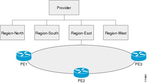
In Prime Fulfillment, a provider administrative domain (PAD) is a single AS. It is not a specific service provider, rather it is a logical container for Regions and PEs.
Within a single PAD, there must be one or more Regions. Regions are logical entities that can be defined in any way that makes sense to a service provider.
Within a Region, a Provider can contain one or more PEs. The PEs can be a PE-POP ("router") or a PE-CLE ("switch").
Figure 21-4 shows an overview of an Prime Fulfillment Provider.
Figure 21-4 Overview of a Prime Fulfillment Provider
This section covers the following topics:
Creating a Provider
To create a provider, perform the following steps.
Step 1 ![]() Choose Service Design > Resources > Providers.
Choose Service Design > Resources > Providers.
The Providers window appears.
Step 2 ![]() Click Create.
Click Create.
The Create New Provider window appears.
Step 3 ![]() In the Name field, enter a provider name.
In the Name field, enter a provider name.
Step 4 ![]() In the BGP AS (Border Gateway Protocol Autonomous System) field, enter a a valid value (1-65535).
In the BGP AS (Border Gateway Protocol Autonomous System) field, enter a a valid value (1-65535).
Step 5 ![]() Enter contact information as applicable.
Enter contact information as applicable.
Step 6 ![]() Click Save.
Click Save.
Creating a Region for PE
To create a region, perform the following steps.
Step 1 ![]() Choose Inventory > Resources > Provider Regions.
Choose Inventory > Resources > Provider Regions.
The Provider Regions window appears.
Step 2 ![]() Click Create.
Click Create.
The Create New Provider Region window appears.
Step 3 ![]() In the Name field, enter a provider region name.
In the Name field, enter a provider region name.
Step 4 ![]() In the Provider field, accept the default value, if one is shown, or to choose a provider, click Select.
In the Provider field, accept the default value, if one is shown, or to choose a provider, click Select.
Step 5 ![]() Click Save.
Click Save.
Creating PEs
To set up a device as a Provider Edge (PE) device, perform the following steps.
Step 1 ![]() Choose Inventory > Resources > Provider Devices.
Choose Inventory > Resources > Provider Devices.
The Provider Devices window appears.
Step 2 ![]() Click Create.
Click Create.
The Create New Provider Devices window appears.
Step 3 ![]() In the Device Name field, click Select.
In the Device Name field, click Select.
The Select Device window appears.
Step 4 ![]() Check to choose a device, then click Select.
Check to choose a device, then click Select.
Step 5 ![]() In the PE Region Name field, click Select.
In the PE Region Name field, click Select.
The Select Region window appears.
Step 6 ![]() Check to choose a region, then click Select.
Check to choose a region, then click Select.
Step 7 ![]() From the drop-down list, choose a PE Role Type (N-PE, U-PE, P, or PE-AGG).
From the drop-down list, choose a PE Role Type (N-PE, U-PE, P, or PE-AGG).
Note ![]() If the role type is N-PE, you can check the 6VPE check box to designate the device as a 6VPE device. See Chapter 23, "IPv6 and 6VPE Support in MPLS VPN" for more information on IPv6 and 6VPE support in Prime Fulfillment.
If the role type is N-PE, you can check the 6VPE check box to designate the device as a 6VPE device. See Chapter 23, "IPv6 and 6VPE Support in MPLS VPN" for more information on IPv6 and 6VPE support in Prime Fulfillment.
Step 8 ![]() Click Save.
Click Save.
The PE Device window appears showing the PE device you have created.
Editing PEs
To view or edit a PE, perform the following steps.
Step 1 ![]() Choose Inventory > Resources > Provider Devices.
Choose Inventory > Resources > Provider Devices.
The Provider Devices window appears.
Step 2 ![]() Choose the PE Device and click Edit.
Choose the PE Device and click Edit.
The Edit PE Device window appears.
Step 3 ![]() Make required changes, then click Save.
Make required changes, then click Save.
Creating Access Domains
Note ![]() This section is only required for Layer 2 access to MPLS VPN.
This section is only required for Layer 2 access to MPLS VPN.
Any Transport over MPLS (AToM) is the Cisco solution for transporting Layer 2 traffic over an IP/MPLS backbone. AToM is required for supporting legacy services over MPLS infrastructures and for supporting new connectivity options, including Layer 2 VPNs and Layer 2 virtual leased lines.
AToM supports three types of Ethernet-based L2VPNs (EoMPLS):
•![]() Point-to-Point Ethernet Wire Service (EWS)
Point-to-Point Ethernet Wire Service (EWS)
•![]() Point-to-Point Ethernet Relay Service (ERS)
Point-to-Point Ethernet Relay Service (ERS)
•![]() Multipoint TLS Service
Multipoint TLS Service
The Layer 2 Ethernet switching domain that connects a PE to a CE is called an Access Domain. All the switches attached to the PE-POP belong to this Access Domain. These switches belong to the Provider and are defined in Prime Fulfillment as PE-CLE.
Note ![]() To have Prime Fulfillment automatically assign VLAN links from a VLAN pool, you must create an Access Domain.
To have Prime Fulfillment automatically assign VLAN links from a VLAN pool, you must create an Access Domain.
Prime Fulfillment supports multiple PE-POPs per Access Domain and multiple PE-CLE devices can be included. Figure 21-5 shows an overview of an Prime Fulfillment Access Domain.
Figure 21-5 Overview of an Access Domain
To create an Access Domain, perform the following steps.
Step 1 ![]() Choose Inventory > Resources > Access Domain.
Choose Inventory > Resources > Access Domain.
The Access Domain window apprears.
Step 2 ![]() Click Create.
Click Create.
The Create New Access Domain window appears, as shown in Figure 21-6.
Figure 21-6 Create New Access Domain
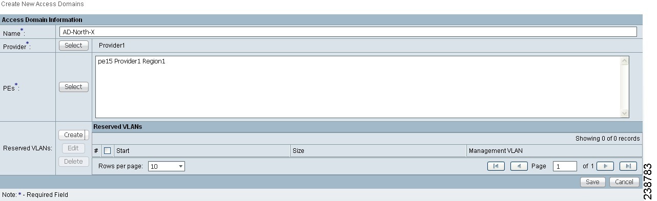
Step 3 ![]() Enter an Access Domain Name.
Enter an Access Domain Name.
Step 4 ![]() Choose a Provider.
Choose a Provider.
Step 5 ![]() Click Select to show PEs.
Click Select to show PEs.
The Show PEs window appears.
Step 6 ![]() Choose a PE by clciking Select.
Choose a PE by clciking Select.
Step 7 ![]() From the Select P E Device(s) window, select a PE and click Select.
From the Select P E Device(s) window, select a PE and click Select.
You are returned to the Create Access Domain window.
Step 8 ![]() For Reserved VLANs, click Create.
For Reserved VLANs, click Create.
The Create Reserved VLAN window appears.
Step 9 ![]() Enter a Starting Value.
Enter a Starting Value.
Step 10 ![]() Enter a Size.
Enter a Size.
Step 11 ![]() Check to choose Management VLAN.
Check to choose Management VLAN.
Step 12 ![]() Click OK.
Click OK.
The Access Domains window appears showing that the Access Domain has been saved in the Repository.
Creating Resource Pools
This section describes how to create Resource Pools using the Prime Fulfillment GUI. It contains the following sections:
•![]() Creating an IPv4 Address Pool
Creating an IPv4 Address Pool
•![]() Creating a Route Distinguisher Pool
Creating a Route Distinguisher Pool
•![]() Creating a Site of Origin Pool
Creating a Site of Origin Pool
Overview of Resource Pools
Before creating a service in Prime Fulfillment, you must define your Resource Pools. From these Resource Pools, Prime Fulfillment can automatically assign some values during the provisioning process. You can also manually assign these values during the provisioning process, but it is not recommended.
Prime Fulfillment allocates numbers from the following pools during the provisioning process:
•![]() IPv4 Address—Connects PE and CE interfaces, when you define addresses in a service request.
IPv4 Address—Connects PE and CE interfaces, when you define addresses in a service request.
Note ![]() IPv6 address pools are not supported in this release.
IPv6 address pools are not supported in this release.
•![]() Multicast—Class D addresses used with multicast, when building PE to multiple CE links.
Multicast—Class D addresses used with multicast, when building PE to multiple CE links.
•![]() Route Distinguisher (RD)—A 64-bit number composed of the Provider AS number and an index number that is prepended to a VPN route. The RD allows the route subnet to be unique across the entire provider MPLS VPN network. It is carried by MP-BGPv4 as a 96-bit VPNv4 address as part of the extended community string.
Route Distinguisher (RD)—A 64-bit number composed of the Provider AS number and an index number that is prepended to a VPN route. The RD allows the route subnet to be unique across the entire provider MPLS VPN network. It is carried by MP-BGPv4 as a 96-bit VPNv4 address as part of the extended community string.
•![]() Route Target (RT)—An import and export feature of a VRF, the RT allows VPN routes to be forwarded between VRFs. It is a 64-bit number, also carried as part of the MP-BGPv4 extended community string, and directly related to each VPNv4 route and its VPN-related IPv4 route.
Route Target (RT)—An import and export feature of a VRF, the RT allows VPN routes to be forwarded between VRFs. It is a 64-bit number, also carried as part of the MP-BGPv4 extended community string, and directly related to each VPNv4 route and its VPN-related IPv4 route.
•![]() Site of Origin (SOO)—Indicates the origin of a BGP update. The Site of Origin ia used by BGP to preclude routing loops.
Site of Origin (SOO)—Indicates the origin of a BGP update. The Site of Origin ia used by BGP to preclude routing loops.
•![]() Virtual Circuit Identifier (VC ID)—Used as a Layer 2 circuit identifier across a provider network.
Virtual Circuit Identifier (VC ID)—Used as a Layer 2 circuit identifier across a provider network.
•![]() VLAN—Used in a Layer 2 VPN as a circuit identifier within the provider Access Domain.
VLAN—Used in a Layer 2 VPN as a circuit identifier within the provider Access Domain.
Note ![]() The VLAN pool does not supply a value for a second VLAN ID, when that feature is used for Q-in-Q matching. See the section Notes on the VLAN ID and Second VLAN ID Attributes, page 25-7 for additional information about second VLAN ID.
The VLAN pool does not supply a value for a second VLAN ID, when that feature is used for Q-in-Q matching. See the section Notes on the VLAN ID and Second VLAN ID Attributes, page 25-7 for additional information about second VLAN ID.
Creating an IPv4 Address Pool
To create an IPv4 address pool, perform the following steps.
Step 1 ![]() Choose Service Design > Resources > Resource Pools.
Choose Service Design > Resources > Resource Pools.
The Resource Pools window appears.
Step 2 ![]() Choose IPV4 Address from the Pool Type drop-down list.
Choose IPV4 Address from the Pool Type drop-down list.
Step 3 ![]() Click Create.
Click Create.
The Create New IP Address Resouce Pool window appears.
Figure 21-7 Create New IP Address Pool
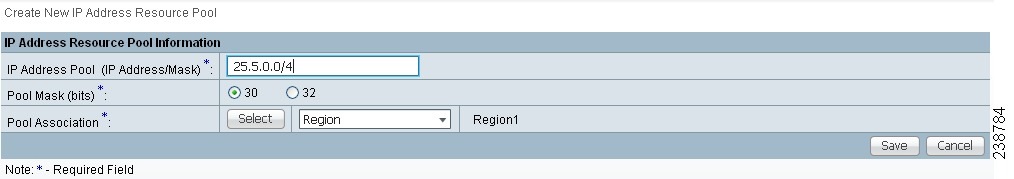
Step 4 ![]() Enter an IP Address and Mask.
Enter an IP Address and Mask.
Step 5 ![]() Choose the Pool Mask (bits) value (30).
Choose the Pool Mask (bits) value (30).
Note ![]() Use 32 for loopback addresses.
Use 32 for loopback addresses.
Step 6 ![]() Click Select to associate the pool to a region.
Click Select to associate the pool to a region.
The Select Region window appears.
Step 7 ![]() Choose a Region.
Choose a Region.
Step 8 ![]() Click Select.
Click Select.
Step 9 ![]() Click Save.
Click Save.
The Resource Pools window appears showing that the IP Address Pool is in the Repository.
Creating a Multicast Pool
To create a multicast pool, perform the following steps.
Step 1 ![]() Choose Service Design > Resources > Resource Pools.
Choose Service Design > Resources > Resource Pools.
The Resource Pools window appears.
Step 2 ![]() Choose Multicast from the Pool Type drop-down list.
Choose Multicast from the Pool Type drop-down list.
Step 3 ![]() Click Create.
Click Create.
The Create New Multicast Resource Pool window appears.
Step 4 ![]() Enter an IP Address and Mask.
Enter an IP Address and Mask.
Step 5 ![]() Choose the defaults (Default MDT and Data MDT).
Choose the defaults (Default MDT and Data MDT).
Step 6 ![]() Click Save.
Click Save.
The Resource Pools appears showing the Multicast Address Pool in the Repository.
Creating a Route Distinguisher Pool
To create a route distinguisher (RD) pool, perform the following steps.
Step 1 ![]() Choose Service Design > Resources > Resource Pools.
Choose Service Design > Resources > Resource Pools.
The Resource Pools window appears.
Step 2 ![]() Choose Route Distinguisher from the Pool Type drop-down list.
Choose Route Distinguisher from the Pool Type drop-down list.
Step 3 ![]() Click Create.
Click Create.
The Create New Route Distinguisher Resource Pool window appears.
Step 4 ![]() Enter an RD Pool Start value.
Enter an RD Pool Start value.
Step 5 ![]() Enter an RD Pool Size value.
Enter an RD Pool Size value.
Step 6 ![]() Click Select.
Click Select.
The Select Provider window appears.
Step 7 ![]() Choose a Provider.
Choose a Provider.
Step 8 ![]() Click Select.
Click Select.
Step 9 ![]() Click Save.
Click Save.
The Resource Pools window appears showing the Route Distinguisher Pool in the Repository.
Creating a Route Target Pool
To create a route target (RT) pool, perform the following steps.
Step 1 ![]() Choose Service Design > Resources > Resource Pools.
Choose Service Design > Resources > Resource Pools.
The Resource Pools window appears.
Step 2 ![]() Choose Route Target from the Pool Type drop-down list.
Choose Route Target from the Pool Type drop-down list.
Step 3 ![]() Click Create.
Click Create.
The Create New Route Target Resource Pool window appears.
Step 4 ![]() Enter an RT Pool Start value.
Enter an RT Pool Start value.
Step 5 ![]() Enter an RT Pool Size value.
Enter an RT Pool Size value.
Step 6 ![]() Click Select.
Click Select.
The Select Provider window appears.
Step 7 ![]() Choose a Provider.
Choose a Provider.
Step 8 ![]() Click Select.
Click Select.
Step 9 ![]() Click Save.
Click Save.
The Resource Pools window appears showing the Route Target Pool in the Repository.
Creating a Site of Origin Pool
To create a site of origin (SOO) pool, perform the following steps.
Step 1 ![]() Choose Service Design > Resources > Resource Pools.
Choose Service Design > Resources > Resource Pools.
The Resource Pools window appears.
Step 2 ![]() Choose Site of Origin from the Pool Type drop-down list.
Choose Site of Origin from the Pool Type drop-down list.
Step 3 ![]() Click Create.
Click Create.
The Create New Site of Origin Resource Pool window appears.
Step 4 ![]() Enter an SOO Pool Start value.
Enter an SOO Pool Start value.
Step 5 ![]() Enter an SOO Pool Size value.
Enter an SOO Pool Size value.
Step 6 ![]() Click Select.
Click Select.
The Select Provider window appears.
Step 7 ![]() Choose a Provider.
Choose a Provider.
Step 8 ![]() Click Select.
Click Select.
Step 9 ![]() Click Save.
Click Save.
The Create New Site of Origin Resource Pool window appears showing a Site of Origin Pool in the Repository.
Creating a VC ID Pool
To create a VC ID pool, perform the following steps.
Step 1 ![]() Choose Service Design > Resources > Resource Pools.
Choose Service Design > Resources > Resource Pools.
The Resource Pools window appears.
Step 2 ![]() Choose VC ID from the Pool Type drop-down list.
Choose VC ID from the Pool Type drop-down list.
Step 3 ![]() Click Create.
Click Create.
The Create New VC ID Resource Pool window appears.
Step 4 ![]() Enter an VC Pool Start value.
Enter an VC Pool Start value.
Step 5 ![]() Enter an VC Pool Size value.
Enter an VC Pool Size value.
Step 6 ![]() Click Save.
Click Save.
The Resource Pools window appears showing a VC ID Pool in the Repository.
Creating a VLAN Pool
To create a VLAN pool, perform the following steps.
Step 1 ![]() Choose Service Design > Resources > Resource Pools.
Choose Service Design > Resources > Resource Pools.
The Resource Pools window appears.
Step 2 ![]() Choose VLAN from the Pool Type drop-down list.
Choose VLAN from the Pool Type drop-down list.
Step 3 ![]() Click Create.
Click Create.
The Create New VLAN Resource Pool window appears.
Step 4 ![]() In the VLAN Pool Start field, enter a valid value.
In the VLAN Pool Start field, enter a valid value.
Step 5 ![]() In the VLAN Pool Size field, enter a valid value.
In the VLAN Pool Size field, enter a valid value.
Step 6 ![]() Choose an access domain by clicking Select.
Choose an access domain by clicking Select.
The Select Access Domain window appears.
Step 7 ![]() Choose an Access Domain.
Choose an Access Domain.
Step 8 ![]() Click Select.
Click Select.
Step 9 ![]() Click Save.
Click Save.
The Create New VLAN Resource Pool window appears showing the VLAN Pool in the Repository.
Note ![]() The VLAN pool does not supply a value for a second VLAN ID, when that feature is used for Q-in-Q matching. See the section Notes on the VLAN ID and Second VLAN ID Attributes, page 25-7 for additional information about second VLAN ID.
The VLAN pool does not supply a value for a second VLAN ID, when that feature is used for Q-in-Q matching. See the section Notes on the VLAN ID and Second VLAN ID Attributes, page 25-7 for additional information about second VLAN ID.
Defining VPNs
During service deployment, Prime Fulfillment generates the Cisco IOS commands to configure the logical VPN relationships. At the beginning of the provisioning process, before creating a Service Policy, a VPN can be defined within Prime Fulfillment.
Note ![]() It is also possible to specify VPN and VRF information in an independent VRF object, which is subsequently deployed to a PE device and then associated with an MPLS VPN link via an MPLS VPN service request. For details on using this feature, see Chapter 22, "Independent VRF Management."
It is also possible to specify VPN and VRF information in an independent VRF object, which is subsequently deployed to a PE device and then associated with an MPLS VPN link via an MPLS VPN service request. For details on using this feature, see Chapter 22, "Independent VRF Management."
This section describes how to define MPLS VPNs and IP Multicast VPNs. It contains the following sections:
•![]() Enabling a Unique Route Distinguisher for a VPN
Enabling a Unique Route Distinguisher for a VPN
Creating an MPLS VPN
At its simplest, a virtual private network (VPN) is a collection of sites that share the same routing table. A VPN is also a framework that provides private IP networking over a public infrastructure such as the Internet. In Prime Fulfillment, a VPN is a set of customer sites that are configured to communicate through a VPN service. A VPN is defined by a set of administrative policies.
A VPN is a network in which two sites can communicate over the provider's network in a private manner; that is, no site outside the VPN can intercept their packets or inject new packets. The provider network is configured such that only one VPN's packets can be transmitted through that VPN—that is, no data can come in or out of the VPN unless it is specifically configured to allow it. There is a physical connection from the provider edge network to the customer edge network, so authentication in the conventional sense is not required.
To create an MPLS VPN, perform the following steps.
Step 1 ![]() Choose Inventory > Logical Inventory > VPNs.
Choose Inventory > Logical Inventory > VPNs.
The VPNs window appears.
Step 2 ![]() From the VPNs window, click Create.
From the VPNs window, click Create.
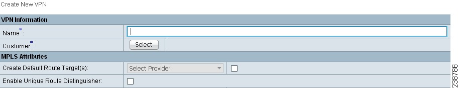
The Create New VPN window appears, as shown in Figure 21-8.
Figure 21-8 Create New VPN
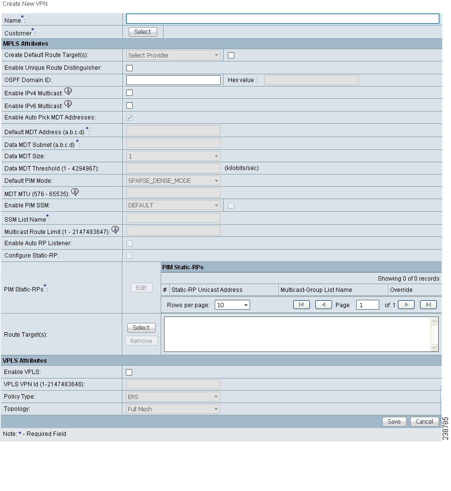
Step 3 ![]() Enter the name of the VPN in the Name field.
Enter the name of the VPN in the Name field.
Step 4 ![]() Click Select and choose a customer associated with this VPN from the Customer filed.
Click Select and choose a customer associated with this VPN from the Customer filed.
Step 5 ![]() To create a default routing community, check the Create Default Route Target(s) check box and choose a provider.
To create a default routing community, check the Create Default Route Target(s) check box and choose a provider.
Step 6 ![]() To enable the unique router distinguisher, check the check box.For coverage of this attribute see Enabling a Unique Route Distinguisher for a VPN
To enable the unique router distinguisher, check the check box.For coverage of this attribute see Enabling a Unique Route Distinguisher for a VPN
Step 7 ![]() Enter the OSPF domain IDvalue in decimal format. The Hex value field is a non-editable text field that displays the equivalent hex value. The hex value is what actually gets displayed on the device.
Enter the OSPF domain IDvalue in decimal format. The Hex value field is a non-editable text field that displays the equivalent hex value. The hex value is what actually gets displayed on the device.
•![]() You can modify the OSPF domain ID at any time. If you attempt to modify the OSPF domain ID for a VPN that is already deployed, all the service requests that use this VPN and have the attribute Use VRF/VPN Domain ID enabled are moved to the Requested state. Prime Fulfillment provides a list of the service requests that were moved to Requested, so that you can deploy them. This operation is similar to enable/disable multicast for a deployed VPN.
You can modify the OSPF domain ID at any time. If you attempt to modify the OSPF domain ID for a VPN that is already deployed, all the service requests that use this VPN and have the attribute Use VRF/VPN Domain ID enabled are moved to the Requested state. Prime Fulfillment provides a list of the service requests that were moved to Requested, so that you can deploy them. This operation is similar to enable/disable multicast for a deployed VPN.
•![]() OSPF domain ID is supported only on IOS XR devices. In the case of IOS devices, Prime Fulfillment ignores the this attribute if you select a VPN with an OSPF domain ID specified.
OSPF domain ID is supported only on IOS XR devices. In the case of IOS devices, Prime Fulfillment ignores the this attribute if you select a VPN with an OSPF domain ID specified.
•![]() For additional information, see the discussion of the OSPF Domain ID attribute in Chapter 24, "OSPF Protocol Chosen".
For additional information, see the discussion of the OSPF Domain ID attribute in Chapter 24, "OSPF Protocol Chosen".
Step 8 ![]() To enable multicast for the VPN, you can check the Enable IPv4 Multicast or Enable IPv6 Multicast check boxes. See Creating an IP Multicast VPN.
To enable multicast for the VPN, you can check the Enable IPv4 Multicast or Enable IPv6 Multicast check boxes. See Creating an IP Multicast VPN.
Note ![]() These attributes are not supported for use with MVRFCE policies and service requests.
These attributes are not supported for use with MVRFCE policies and service requests.
Note ![]() Enable IPv6 Multicast is not supported on IOS and IOS 6VPE devices.
Enable IPv6 Multicast is not supported on IOS and IOS 6VPE devices.
Note ![]() Next set of attributes (up to Route Target(s)) only become active in the GUI if one of the enable multicast attributes is checked. See Creating an IP Multicast VPN, for coverage of these attributes.
Next set of attributes (up to Route Target(s)) only become active in the GUI if one of the enable multicast attributes is checked. See Creating an IP Multicast VPN, for coverage of these attributes.
Step 9 ![]() Route Target(s): If you do not choose to enable the default Route Target(s), you can choose a customized Route Target(s) that you have already created in Prime Fulfillment (see Creating Route Target(s)).
Route Target(s): If you do not choose to enable the default Route Target(s), you can choose a customized Route Target(s) that you have already created in Prime Fulfillment (see Creating Route Target(s)).
Note ![]() You must specify a CERC if multicast is enabled.
You must specify a CERC if multicast is enabled.
a. ![]() From the CE Routing Communities pane, click Select.
From the CE Routing Communities pane, click Select.
The Select CE Routing Communities dialog box appears.
b. ![]() Check the check box for the CERC you want used for this VPN, then click Select.
Check the check box for the CERC you want used for this VPN, then click Select.
You return to the Create VPN dialog box, where the new CERC selection appears, along with its hub route target (HRT) and spoke route target (SRT) values.
Step 10 ![]() Check the Enable VPLS check box to enable VPLS.
Check the Enable VPLS check box to enable VPLS.
Step 11 ![]() Choose the VPLS service type from the Service Type drop-down menu: ERS (Ethernet Relay Service) or EWS (Ethernet Wire Service).
Choose the VPLS service type from the Service Type drop-down menu: ERS (Ethernet Relay Service) or EWS (Ethernet Wire Service).
Step 12 ![]() Choose the VPLS topology from the drop-down menu: Full Mesh (each CE will have direct connections to every other CE) or Hub and Spoke (only the Hub CE has connection to each Spoke CE and the Spoke CEs do not have direct connection to each other).
Choose the VPLS topology from the drop-down menu: Full Mesh (each CE will have direct connections to every other CE) or Hub and Spoke (only the Hub CE has connection to each Spoke CE and the Spoke CEs do not have direct connection to each other).
Step 13 ![]() When satisfied with the settings for this VPN, click Save.
When satisfied with the settings for this VPN, click Save.
You have successfully created a VPN, as shown in the Status display in the lower left corner of the VPNs dialog box.
Creating an IP Multicast VPN
An IP address that starts with the binary prefix 1110 is identified as a multicast group address. There can be more than one sender and receiver at any time for a given multicast group address. The senders send their data by setting the group address as the destination IP address. It is the responsibility of the network to deliver this data to all the receivers in the network who are listening to that group address.
Note ![]() Before you can create a VPN with multicast enabled, you must define one or more multicast resource pools. See Creating a Multicast Pool, for further information.
Before you can create a VPN with multicast enabled, you must define one or more multicast resource pools. See Creating a Multicast Pool, for further information.
If the multicast VPN is used in a service request on a device running IOS XR, not all of the multicast attributes in the Create VPN window are supported. This is because there is not a one-to-one mapping of IOS multicast commands to IOS XR commands. These exceptions are noted in the following steps. For a comparison of multicast routing commands in IOS and IOS XR, see Chapter 23, "Multicast Routing on IOS and IOS XR Devices".
Multicast VRF deployments are supported also. For more information about VRF object support in Prime Fulfillment, see Chapter 22, "Independent VRF Management."
To create an IP Multicast VPN, follow the procedure described in Creating an MPLS VPN to the place where you can enable multicast for the VPN, then perform the following steps.
Step 1 ![]() Check one or both of Enable IPv4 Multicast or Enable IPv6 Multicast check boxes to enable multicast for the VPN.
Check one or both of Enable IPv4 Multicast or Enable IPv6 Multicast check boxes to enable multicast for the VPN.
Note ![]() Enable IPv6 Multicast is not supported on IOS and IOS 6VPE devices.
Enable IPv6 Multicast is not supported on IOS and IOS 6VPE devices.
The current window refreshes with additional fields becoming active.
Usage notes:
•![]() For IOS XR PE devices running release 3.7.0 or later, Prime Fulfillment allows a multicast VPN to be deployed on an IPv6 PE-CE link and multicast to be enabled during the creation of the VRF object.
For IOS XR PE devices running release 3.7.0 or later, Prime Fulfillment allows a multicast VPN to be deployed on an IPv6 PE-CE link and multicast to be enabled during the creation of the VRF object.
•![]() When creating a VPN, you can enable multicast for IPv4, IPv6, or both. You can enter IPv6 addresses as static Rendezvous Point (RP) addresses if IPv6 multicast is enabled during the creation of a VPN or VRF object.
When creating a VPN, you can enable multicast for IPv4, IPv6, or both. You can enter IPv6 addresses as static Rendezvous Point (RP) addresses if IPv6 multicast is enabled during the creation of a VPN or VRF object.
•![]() You can also modify an existing VPN object to enable multicast for IPv4, IPv6, or both. When IPv4 multicast is enabled, all deployed service requests containing IPv4 links of the same VPN are moved into Requested state.
You can also modify an existing VPN object to enable multicast for IPv4, IPv6, or both. When IPv4 multicast is enabled, all deployed service requests containing IPv4 links of the same VPN are moved into Requested state.
•![]() In addition, you can specify within the MPLS service request whether you want to enable multicast for IPv4, IPv6, or both on a given MPLS link.
In addition, you can specify within the MPLS service request whether you want to enable multicast for IPv4, IPv6, or both on a given MPLS link.
•![]() When IPv6 multicast is enabled, all deployed service requests containing IPv6 links of the same VPN are moved into Requested state. If IPv4 is previously configured and only IPv6 multicast is enabled in a VPN, only the service requests with IPv6 links are moved into Requested state.
When IPv6 multicast is enabled, all deployed service requests containing IPv6 links of the same VPN are moved into Requested state. If IPv4 is previously configured and only IPv6 multicast is enabled in a VPN, only the service requests with IPv6 links are moved into Requested state.
•![]() You can modify an existing VPN object and add IPv6 static RP addresses when IPv6 multicast is enabled. Any service requests already in Deployed state are then moved to the Requested state.
You can modify an existing VPN object and add IPv6 static RP addresses when IPv6 multicast is enabled. Any service requests already in Deployed state are then moved to the Requested state.
•![]() You can create a service policy or an MPLS VPN link in the service request with IPv6 Numbered or IPv4+IPv6 Numbered as the IP addressing scheme and a multicast VPN with multicast enabled.
You can create a service policy or an MPLS VPN link in the service request with IPv6 Numbered or IPv4+IPv6 Numbered as the IP addressing scheme and a multicast VPN with multicast enabled.
Step 2 ![]() For MDT (Multicast Distribution Tree) addresses, either accept the default (check box already checked) to enable the auto pick function, or uncheck the auto pick check box, then enter values in the next two fields:
For MDT (Multicast Distribution Tree) addresses, either accept the default (check box already checked) to enable the auto pick function, or uncheck the auto pick check box, then enter values in the next two fields:
•![]() Default MDT Address
Default MDT Address
•![]() Data MDT Subnet
Data MDT Subnet
Step 3 ![]() From the Data MDT Size drop-down list, choose a value for Data MDT Size.
From the Data MDT Size drop-down list, choose a value for Data MDT Size.
Step 4 ![]() In the Data MDT Threshold field, enter a valid value for Data MDT Threshold (1 - 4294967 kilobits/sec).
In the Data MDT Threshold field, enter a valid value for Data MDT Threshold (1 - 4294967 kilobits/sec).
Step 5 ![]() For Default PIM (Protocol Independent Multicast) Mode, choose a mode from the Default PIM Mode drop-down list:
For Default PIM (Protocol Independent Multicast) Mode, choose a mode from the Default PIM Mode drop-down list:
•![]() SPARSE_MODE
SPARSE_MODE
•![]() SPARSE_DENSE_MODE
SPARSE_DENSE_MODE
Tip ![]() Multicast routing architecture allows the addition of IP multicast routing on existing IP networks. PIM is an independent unicast routing protocol. It can be operated in two modes: dense and sparse.
Multicast routing architecture allows the addition of IP multicast routing on existing IP networks. PIM is an independent unicast routing protocol. It can be operated in two modes: dense and sparse.
Note ![]() For IOS XR devices, when SPARSE_DENSE_MODE is chosen, no configlet will be generated. Sparse-dense mode is not supported by IOS XR, only sparse mode (default) and bidirectional mode. For IOS XR devices, sparse mode is running by default when multicast routing is enabled on an interface. Hence, no configlet will be generated for sparse mode either.
For IOS XR devices, when SPARSE_DENSE_MODE is chosen, no configlet will be generated. Sparse-dense mode is not supported by IOS XR, only sparse mode (default) and bidirectional mode. For IOS XR devices, sparse mode is running by default when multicast routing is enabled on an interface. Hence, no configlet will be generated for sparse mode either.
Step 6 ![]() In the MDT MTU field, enter a valid value for MDT MTU (Maximum Transmission Unit).
In the MDT MTU field, enter a valid value for MDT MTU (Maximum Transmission Unit).
Note ![]() The ranges for IOS and IOS XR devices for this attribute are different. The range for IOS devices is from 576 to 18010, and for IOS XR devices it is from 1401 to 65535. Device type validations are done during service request creation when it is known what type of device the multicast VPN will be deployed on.
The ranges for IOS and IOS XR devices for this attribute are different. The range for IOS devices is from 576 to 18010, and for IOS XR devices it is from 1401 to 65535. Device type validations are done during service request creation when it is known what type of device the multicast VPN will be deployed on.
Step 7 ![]() To enable PIM SSM (Source Specific Multicast), check the associated check box.
To enable PIM SSM (Source Specific Multicast), check the associated check box.
When you check the check box:
a. ![]() The associated drop-down list goes active with the DEFAULT enumeration populated as the SSM default. This will create the following CLI: ip pim vrf vrfName ssm default.
The associated drop-down list goes active with the DEFAULT enumeration populated as the SSM default. This will create the following CLI: ip pim vrf vrfName ssm default.
Note ![]() For IOS XR devices, when DEFAULT is chosen, no configlet will be generated because this command is running by default on IOS XR devices, using the standard SSM range 232.0.0.0/8.
For IOS XR devices, when DEFAULT is chosen, no configlet will be generated because this command is running by default on IOS XR devices, using the standard SSM range 232.0.0.0/8.
b. ![]() If you would like to associate an access-list number, or a named access-list, with SSM configuration, choose the RANGE enumeration from the SSM drop-down list instead of DEFAULT. This will create the following CLI: ip pim vrf vrfName ssm range {ACL# | named-ACL-name}.
If you would like to associate an access-list number, or a named access-list, with SSM configuration, choose the RANGE enumeration from the SSM drop-down list instead of DEFAULT. This will create the following CLI: ip pim vrf vrfName ssm range {ACL# | named-ACL-name}.
Step 8 ![]() If you choose RANGE in the previous step, then the SSM List Name field goes active for you to enter Access-list number or Access-list name.
If you choose RANGE in the previous step, then the SSM List Name field goes active for you to enter Access-list number or Access-list name.
Step 9 ![]() In the Multicast Route Limit field, enter a valid value for the Multicast Route Limit (1-2147483647).
In the Multicast Route Limit field, enter a valid value for the Multicast Route Limit (1-2147483647).
Usage notes:
•![]() The command to set the route limit per VRF is supported for both IOS and IOS XR.
The command to set the route limit per VRF is supported for both IOS and IOS XR.
•![]() The range listed in the GUI (1-2147483647) is for IOS. For IOS XR, the range is 1-200000. To display information on the range values in the GUI, click the tool tip icon for the attribute.
The range listed in the GUI (1-2147483647) is for IOS. For IOS XR, the range is 1-200000. To display information on the range values in the GUI, click the tool tip icon for the attribute.
•![]() Prime Fulfillment performs device-specific validations of the value when a service request is created using the VPN or VRF object using this attribute.
Prime Fulfillment performs device-specific validations of the value when a service request is created using the VPN or VRF object using this attribute.
•![]() The value of Multicast Route Limit is shared for both IPv4 and IPv6 address families.
The value of Multicast Route Limit is shared for both IPv4 and IPv6 address families.
Step 10 ![]() To enable the auto RP (Rendezvous Point) listener function, check the Enable Auto RP Listener check box.
To enable the auto RP (Rendezvous Point) listener function, check the Enable Auto RP Listener check box.
Note ![]() For IOS XR devices, no configlet is generated for this attribute. By default, this feature is running on IOS XR devices.
For IOS XR devices, no configlet is generated for this attribute. By default, this feature is running on IOS XR devices.
Step 11 ![]() To configure Static RPs, check the Configure Static-RP check box.
To configure Static RPs, check the Configure Static-RP check box.
When you check this, the Edit option for PIM Static RPs goes active.
Step 12 ![]() To edit or add PIM Static RPs, click Edit in the PIM Static RPs area.
To edit or add PIM Static RPs, click Edit in the PIM Static RPs area.
The Edit PIM Static RPs window appears.
Step 13 ![]() Complete all applicable fields in the Edit PIM Static RP window, then click OK.
Complete all applicable fields in the Edit PIM Static RP window, then click OK.
The data now appears in the main Create VPN window.
Step 14 ![]() To save your changes and add this Multicast VPN to your system, at the bottom of the window, click Save.
To save your changes and add this Multicast VPN to your system, at the bottom of the window, click Save.
Enabling a Unique Route Distinguisher for a VPN
Note ![]() In ISC 6.0, enabling unique route distinguishers is supported for both IOS and IOS XR PE devices. It is also supported for IPv6 and dual-stacked services.
In ISC 6.0, enabling unique route distinguishers is supported for both IOS and IOS XR PE devices. It is also supported for IPv6 and dual-stacked services.
Support for multipath load sharing requires unique route distinguishers (RDs) for each PE router for a VPN (VRF). This is to prevent the same RDs from being allocated to different customers. This allows the use of the same RD for the same VRF. That is, all sites in the PE can have the same unique RD. The unique RD feature is optional. It is enabled at both a global VPN level or a service request level. To enable the unique RD per PE for a VPN, the Create VPN window contains the attribute Enable Unique Route Distinguisher field.
Each VPN deployed through Prime Fulfillment for which Enable Unique Route Distinguisher has been selected is marked as a multipath VPN. This ensures a unique RD allocation for each VRF on each PE. Enabling multipath for an already deployed VPN creates new VRFs on all the PEs of the VPN and assigns a unique RD. When Enable Unique Route Distinguisher is selected for the VPN, the Allocate New Route Distinguisher and VRF and RD Overwrite attributes will be disabled when setting up a policy or service request that uses this VPN.
To use the unique RD feature, perform the following steps.
Step 1 ![]() When creating a VPN, check the Enable Unique Route Distinguisher check box.
When creating a VPN, check the Enable Unique Route Distinguisher check box.
Step 2 ![]() When subsequently creating a service policy and/or service request, select the VPN in the VRF and VPN Membership window.
When subsequently creating a service policy and/or service request, select the VPN in the VRF and VPN Membership window.
The Unique Route Distinguisher field appears.
Step 3 ![]() If the unique RD allocation functionality is required, check the Unique Route Distinguisher check box.
If the unique RD allocation functionality is required, check the Unique Route Distinguisher check box.
For additional information on how this feature is used with MPLS VPN policies and service requests, see Chapter 24, "Defining VRF and VPN Information".
Provisioning MPLS Service Requests Using Unique Route Distinguisher
The unique route distinguisher (RD) feature is used to implement multipath load balancing. Multihomed CEs often require load balancing across multiple available paths. In a full-mesh BGP environment, PEs receive all the available paths to a given prefix, and load balancing can easily be achieved. However, when route reflectors are present in the service provider core, PE routers receive only one route, even if multiple paths exist, and load balancing does not occur. To achieve load balancing, the service provider needs to implement unique RD values for the customer VPN on each PE router. In addition, eiBGP configuration with the desired number of paths (across which load balancing is desired) needs to be enabled in the service provider environment. Figure 21-9 illustrates a load balancing example.
Figure 21-9 Load Balancing Using Different RDs
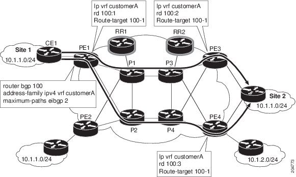
The support for multipath load sharing requires unique RDs for each PE router for a VPN (VRF). This is to prevent the same RDs from being allocated to different customers. This allows the use of the same RD for the same VRF. That is, all sites in the PE can have the same unique RD. The unique RD feature is optional. You can specify its use at both the policy or service request level.
It is enabled at both a global VPN level or a service request level.
Prime Fulfillment supports BGP multipath load sharing through fields and options in the Prime Fulfillment GUI. The following steps provide an overview of how to do this.
Step 1 ![]() When creating a VPN, check the Enable Unique Route Distinguisher check box in the Create VPN window, as shown in Figure 21-10.
When creating a VPN, check the Enable Unique Route Distinguisher check box in the Create VPN window, as shown in Figure 21-10.
Figure 21-10 Enabling Unique RD in Create VPN
For some additional coverage of this, see Enabling a Unique Route Distinguisher for a VPN.
Step 2 ![]() When setting the attributes in the policy (MPLS Policy Editor - VRF and VPN Membership window) or service request (MPLS Link Attribute Editor - VRF and VPN window), use the BGP Multipath Load Sharing check box to enable or disable BGP multipath load sharing.
When setting the attributes in the policy (MPLS Policy Editor - VRF and VPN Membership window) or service request (MPLS Link Attribute Editor - VRF and VPN window), use the BGP Multipath Load Sharing check box to enable or disable BGP multipath load sharing.
Enabling BGP multipath load sharing by checking the check box causes additional attributes to appear in the GUI. For detailed coverage of these attributes and how to set them, see Chapter 24, "BGP Multipath Load Sharing and Maximum Path Configuration".
Step 3 ![]() When creating a service request based on this policy, check the Unique Route Distinguisher check box in the MPLS Link Attribute Editor - VRF and VPN window.
When creating a service request based on this policy, check the Unique Route Distinguisher check box in the MPLS Link Attribute Editor - VRF and VPN window.
Note ![]() The Unique Route Distinguisher attribute is dynamic and only shows up in the GUI if a VPN with unique RD enabled is selected.
The Unique Route Distinguisher attribute is dynamic and only shows up in the GUI if a VPN with unique RD enabled is selected.
Step 4 ![]() Complete the service request creation, and save the service request.
Complete the service request creation, and save the service request.
The following use cases demonstrate the behavior of unique RD feature.
Use case details:
•![]() The default values of the VPN/VRF are:
The default values of the VPN/VRF are:
ip vrf V24:unique2
rd 1:33
route-target import 1:14
route-target import 1:15
route-target export 1:14
•![]() Service requests are created using PEs and enabling or disabling the Unique RD attribute during service request creation, as shown in Table 21-1.
Service requests are created using PEs and enabling or disabling the Unique RD attribute during service request creation, as shown in Table 21-1.
•![]() The outcomes for various cases are described in the Results column of the table.
The outcomes for various cases are described in the Results column of the table.
Creating Route Target(s)
Route Target(s) are the means by which Prime Fulfillment handles the Route Targets (RT) transparently from the users, and it can help the service providers to easily implement various kinds of VPN topology. When you create a VPN, the Prime Fulfillment software creates one default Route Target(s) for you. But if your network topology and configuration require customized Route Target(s) definitions, you can define Route Target(s) customized for your network.
Tip ![]() Customized Route Target(s) should be defined only in consultation with the VPN network administrator.
Customized Route Target(s) should be defined only in consultation with the VPN network administrator.
To build complex topologies, it is necessary to break down the required connectivity between CEs into groups, where each group is either fully meshed, or has a hub-and-spoke pattern. A CE can be in more than one group at a time, so long as each group has one of the two basic configuration patterns.
Each subgroup in the VPN needs its own Route Target(s). Any CE that is only in one group just joins the corresponding Route Target(s) (as a spoke if necessary). If a CE is in more than one group, then you can use the Advanced Setup choice during provisioning to add the CE to all the relevant groups in one service request. Given this information, Prime Fulfillment does the rest, assigning route target values and VRF tables to arrange the precise connectivity the customer requires.
To define a new Route Target(s), perform the following steps.
Step 1 ![]() Choose Service Design > Resources > Route Targets.
Choose Service Design > Resources > Route Targets.
Step 2 ![]() Click Create.
Click Create.
The Create Route Target(s) window appears, as shown in Figure 21-11.
Figure 21-11 Defining a New Route Target
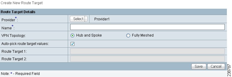
Step 3 ![]() Complete the Route Target(s) fields as required for the VPN:
Complete the Route Target(s) fields as required for the VPN:
a. ![]() Provider: To specify the service provider associated with this Route Target(s), click Select.
Provider: To specify the service provider associated with this Route Target(s), click Select.
The Select Provider dialog box appears.
b. ![]() Choose the name of the service provider, then click Select.
Choose the name of the service provider, then click Select.
c. ![]() Name: Enter the name of the Route Target(s).
Name: Enter the name of the Route Target(s).
d. ![]() VPN Topology: Specify the VPN Topology type: Hub and Spoke or Fully Meshed.
VPN Topology: Specify the VPN Topology type: Hub and Spoke or Fully Meshed.
e. ![]() Auto-pick route target Values: Choose to either let Prime Fulfillment automatically set the route target (RT) values or set the RT values manually.
Auto-pick route target Values: Choose to either let Prime Fulfillment automatically set the route target (RT) values or set the RT values manually.
By default, the Auto-pick route target values check box is checked. If you uncheck the check box, you can enter the Route Target values manually in the Route Target 1 and Route Target 2 fileds.
Note ![]() If you choose to bypass the Auto-pick route target values option and set the route target (RT) values manually, the RT values cannot be edited after they have been defined in the Cisco Prime Fulfillment software.
If you choose to bypass the Auto-pick route target values option and set the route target (RT) values manually, the RT values cannot be edited after they have been defined in the Cisco Prime Fulfillment software.
Step 4 ![]() When you have finished entering the information in the Create Route Target(s) dialog box, click Save.
When you have finished entering the information in the Create Route Target(s) dialog box, click Save.
 Feedback