- About This Book
-
- Getting Started
- Setting Up the Prime Fulfillment Services for L2VPN
- Creating a FlexUNI/EVC Ethernet Policy
- Creating a FlexUNI/EVC Ethernet Service Request
- Creating a FlexUNI/EVC ATM-Ethernet Interworking Policy
- Creating a FlexUNI/EVC ATM-Ethernet Interworking Service Request
- Creating an L2VPN Policy
- Creating an L2VPN Service Request
- Creating a VPLS Policy
- Creating a VPLS Service Request
- Deploying, Monitoring, and Auditing Service Requests
- Using Auto Discovery for L2 Services
- Sample Configlets
- Setting Up VLAN Translation
-
- Getting Started with MPLS VPN
- Setting Up the Prime Fulfillment Services
- Independent VRF Management
- IPv6 and 6VPE Support in MPLS VPN
- MPLS VPN Service Policies
- MPLS VPN Service Requests
- Provisioning Regular PE-CE Links
- Provisioning Multi-VRFCE PE-CE Links
- Provisioning Management VPN
- Provisioning Cable Services
- Provisioning Carrier Supporting Carrier
- Provisioning Multiple Devices
- Spanning Multiple Autonomous Systems
- Sample Configlets
- Troubleshooting MPLS VPNs
Cisco Prime Fulfillment User Guide 6.1
Bias-Free Language
The documentation set for this product strives to use bias-free language. For the purposes of this documentation set, bias-free is defined as language that does not imply discrimination based on age, disability, gender, racial identity, ethnic identity, sexual orientation, socioeconomic status, and intersectionality. Exceptions may be present in the documentation due to language that is hardcoded in the user interfaces of the product software, language used based on RFP documentation, or language that is used by a referenced third-party product. Learn more about how Cisco is using Inclusive Language.
- Updated:
- March 20, 2015
Chapter: Provisioning Multi-VRFCE PE-CE Links
Provisioning Multi-VRFCE PE-CE Links
This chapter describes how to configure MPLS VPN Multi-VRFCE PE-CE links in the Prime Fulfillment provisioning process.
MPLS VPN MVRFCE PE-CE Link Overview
This section contains the following sections:
To provision an MPLS VPN service in Prime Fulfillment, you must first create an MPLS VPN Service Policy. In Prime Fulfillment, a Service Policy is a set of default configurations for creating and deploying a service request. Prime Fulfillment supports two MPLS VPN Service Policy Types: Regular PE-CE an MVRFCE PE-CE. The following scenarios focus on the MVRFCE PE-CE Policy Type. An MVRFCE PE-CE Policy Type is a PE to CE link with three devices:
•![]() PE
PE
•![]() Multi-VRF CE
Multi-VRF CE
•![]() CE
CE
This Policy Type has two options:
•![]() CE Present enabled (One PE with one MVRFCE and one CE; three devices)
CE Present enabled (One PE with one MVRFCE and one CE; three devices)
•![]() CE Present disabled (One PE with one MVRFCE; two devices)
CE Present disabled (One PE with one MVRFCE; two devices)
Figure 26-1 shows an example of an MVRFCE PE-CE link with three devices.
Figure 26-1 MVRFCE PE-CE Link
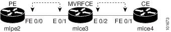
In an MVRFCE PE-CE link with CE Present enabled, interfaces FE 0/0, E 0/1, E 0/2 and FE 0/1 are configured as an MPLS VPN link in the service request process.
Figure 26-2 shows an example of a PE to MVRFCE link with no CE.
Figure 26-2 MVRFCE PE-CE Link with No CE
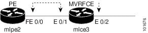
In an MVRFCE PE-CE link with CE Present disabled, interfaces FE 0/0, E 0/1, and E 0/2 are configured as an MPLS VPN link in the service request process.
Network Topology
Figure 26-3 shows an overview of the network topology in which the MPLS VPN MVRFCE PE-CE links are created.
Figure 26-3 Network Topology for MPLS VPN MVRFCE PE-CE Scenarios
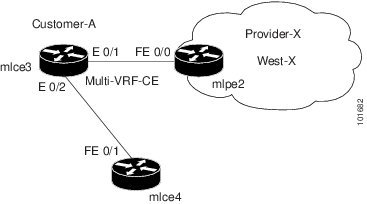
The network topology in Figure 26-3 illustrates the lab environment of a service provider (Provider-X) and one customer (Cust-A). There is one Region (West-X) and one PE (mlpe2.cisco.com). Each customer device (one MVRFCE and one CE) represents a Site (mlce3-Site and mlce4-Site).
Prerequisite Tasks
Before you can create a Service Policy in Prime Fulfillment, you must complete the following Inventory Management tasks:
Step 1 ![]() Set up a Customer with a Site (see Chapter 21, "Creating Customers, Sites, and CPEs").
Set up a Customer with a Site (see Chapter 21, "Creating Customers, Sites, and CPEs").
Step 2 ![]() Setup a Provider with a Region (see Chapter 21, "Creating a Provider").
Setup a Provider with a Region (see Chapter 21, "Creating a Provider").
Step 3 ![]() Import, create, or discover Devices (see Chapter 21, "Creating Devices").
Import, create, or discover Devices (see Chapter 21, "Creating Devices").
Step 4 ![]() Create CPE and PE (see Chapter 21, "Creating CPEs").
Create CPE and PE (see Chapter 21, "Creating CPEs").
Step 5 ![]() Collect Configurations (see Chapter 21, "Collecting Configurations").
Collect Configurations (see Chapter 21, "Collecting Configurations").
Step 6 ![]() Create Resource Pools (see Chapter 21, "Creating Resource Pools").
Create Resource Pools (see Chapter 21, "Creating Resource Pools").
Step 7 ![]() Create CE routing communities (CERC) (see Chapter 21, "Creating Route Target(s)").
Create CE routing communities (CERC) (see Chapter 21, "Creating Route Target(s)").
Step 8 ![]() Define a MPLS VPN (see Chapter 21, "Creating an MPLS VPN").
Define a MPLS VPN (see Chapter 21, "Creating an MPLS VPN").
Defining VPN for MVRFCE PE-CE Links
During service deployment, Prime Fulfillment generates the Cisco IOS commands to configure the logical VPN relationships.
At the beginning of the provisioning process, before creating a Service Policy, a VPN must be defined within Prime Fulfillment. The first element in a VPN definition is the name of the VPN.
To create a VPN Name, perform the following steps.
Step 1 ![]() Choose Inventory > Logical Inventory > VPNs.
Choose Inventory > Logical Inventory > VPNs.
The VPNs window appears.
Step 2 ![]() Click Create to create a VPN.
Click Create to create a VPN.
The Create New VPN window appears.
Step 3 ![]() Edit the following attributes:
Edit the following attributes:
•![]() Name: Enter the VPN name.
Name: Enter the VPN name.
It is recommended not to use special characters (' ` " < > ( ) [ ] { } / \ & ^ ! ? ~ * % = , . + |) in the VPN name, as this may cause misconfiguration of the VRF name for certain devices, if the VPN name is used to autogenerate a VRF name.
•![]() Customer: Click Select.
Customer: Click Select.
The Select Customer window appears.
Step 4 ![]() Choose a Customer and click Select.
Choose a Customer and click Select.
Step 5 ![]() Click Save.
Click Save.

Note ![]() Independent VRF association is not supported for MVRFCE-based policies and service requests.
Independent VRF association is not supported for MVRFCE-based policies and service requests.
Creating MPLS VPN MVRFCE PE-CE Service Policies
This section contains the following sections:
•![]() Creating MVRFCE PE-CE Service Policies
Creating MVRFCE PE-CE Service Policies
•![]() Creating PE-NoCE Service Policies
Creating PE-NoCE Service Policies
Creating MVRFCE PE-CE Service Policies
To create an MVRFCE PE-CE service policy, perform the following steps.
Note ![]() Make sure the Editable check boxes are checked where available, so you can edit these attributes in the service request process.
Make sure the Editable check boxes are checked where available, so you can edit these attributes in the service request process.
Step 1 ![]() Choose Service Design > Policies > MPLS. The MPLS Policy Editor - Policy Type window appears, as shown in Figure 26-4.
Choose Service Design > Policies > MPLS. The MPLS Policy Editor - Policy Type window appears, as shown in Figure 26-4.
Figure 26-4 MPLS - Policy Type Information
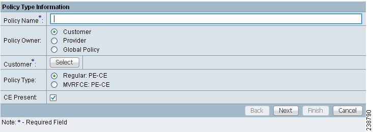
Step 2 ![]() Edit the following attributes:
Edit the following attributes:
•![]() Policy Name: Enter the policy name.
Policy Name: Enter the policy name.
•![]() Policy Owner: Choose the Policy Owner.
Policy Owner: Choose the Policy Owner.
•![]() Customer:
Customer:
–![]() Click Select to specify a customer.
Click Select to specify a customer.
The Customer for MPLS Policy window appears.
–![]() Choose a customer and click Select.
Choose a customer and click Select.
•![]() Policy Type: Choose the Policy Type. (MVRFCE: PE-CE)
Policy Type: Choose the Policy Type. (MVRFCE: PE-CE)
•![]() CE Present: Check to set CE as present.
CE Present: Check to set CE as present.
Step 3 ![]() Click Next.
Click Next.
The MPLS Policy Editor - PE Interface window appears, as shown in Figure 26-5.
Figure 26-5 The MPLS Policy Editor - PE Interface
Step 4 ![]() Click Next.
Click Next.
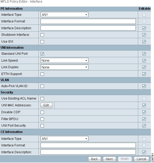
The MPLS Policy Editor - Interface window appears.
Step 5 ![]() Edit all applicable attributes.
Edit all applicable attributes.
Step 6 ![]() Click Next.
Click Next.
The MPLS Policy Editor - IP Address Scheme window appears for PE-MVRFCE.
Step 7 ![]() Edit all applicable attributes.
Edit all applicable attributes.
Step 8 ![]() Click Next.
Click Next.
Step 9 ![]() Another set of MPLS Policy Editor - IP Address Scheme windows appear for MVRFCE-CE.
Another set of MPLS Policy Editor - IP Address Scheme windows appear for MVRFCE-CE.
Step 10 ![]() Edit all applicable attributes, as above.
Edit all applicable attributes, as above.
Step 11 ![]() Click Next.
Click Next.
The MPLS Policy Editor - Routing Information window appears for PE-MVRFCE.
Note ![]() For information about protocol types, see Chapter 24, "Specifying the Routing Protocol for a Service".
For information about protocol types, see Chapter 24, "Specifying the Routing Protocol for a Service".
Step 12 ![]() Click Next to accept the defaults.
Click Next to accept the defaults.
The MPLS Policy Editor - Routing Information window appears for MVRFCE-CE.
Step 13 ![]() Click Next to accept the defaults.
Click Next to accept the defaults.
The MPLS Policy Editor - VRF and VPN Membership window appears.
Step 14 ![]() To enable template association for the policy, click the Next button in MPLS Policy Editor - VRF and VPN Membership window.
To enable template association for the policy, click the Next button in MPLS Policy Editor - VRF and VPN Membership window.
The Template Association window appears. In this window, you can enable template support and, optionally, associate templates and data files with the policy. For instructions about associating templates with policies and how to use the features in this window, see Chapter 49, "Using Templates and Data Files with Policies and Service Requests" When you have completed setting up templates and data files for the policy per the instructions in the appendix, click Finish in the Template Association window to close it.
The Policies window appears.
Step 15 ![]() If you did not enable templates, click Finish in the MPLS Policy Editor - VRF and VPN window.
If you did not enable templates, click Finish in the MPLS Policy Editor - VRF and VPN window.
The Policies window reappears showing that the MPLS VPN MVRFCE PE-CE Service Policy is complete.
Creating PE-NoCE Service Policies
To create a PE-NoCE service policy, perform the following steps.
Step 1 ![]() Choose Service Design > Policies > MPLS.
Choose Service Design > Policies > MPLS.
The MPLS Policy Editor - Policy Type window appears.
Step 2 ![]() Edit the following attributes:
Edit the following attributes:
•![]() Policy Name: Enter the policy name.
Policy Name: Enter the policy name.
•![]() Policy Owner: Choose the Policy Owner.
Policy Owner: Choose the Policy Owner.
•![]() Customer:
Customer:
–![]() Click Select to specify a customer.
Click Select to specify a customer.
The Customer for MPLS Policy window appears.
–![]() Choose a customer and click Select.
Choose a customer and click Select.
•![]() Policy Type: Choose the Policy Type. (Regular PE-CE)
Policy Type: Choose the Policy Type. (Regular PE-CE)
•![]() CE Present: Do not check to set CE as not present (NoCE).
CE Present: Do not check to set CE as not present (NoCE).
Step 3 ![]() Click Next.
Click Next.
The MPLS Policy Editor - Interface window appears.
Step 4 ![]() Click Next to accept the defaults.
Click Next to accept the defaults.
The MPLS Policy Editor - Interface window appears for MVRFCE-CE Facing Information.
Step 5 ![]() Click Next to accept the defaults.
Click Next to accept the defaults.
The MPLS Policy Editor - IP Address Scheme window appears for PE-MVRFCE-CE Interface Address/Mask.
a. ![]() Edit the attributes as indicated:
Edit the attributes as indicated:
b. ![]() IP Numbering Scheme: Choose IP Numbered Scheme.
IP Numbering Scheme: Choose IP Numbered Scheme.
c. ![]() Automatically Assign IP Address: To have Prime Fulfillment automatically assign IP Addresses, check the check box.
Automatically Assign IP Address: To have Prime Fulfillment automatically assign IP Addresses, check the check box.
d. ![]() IP Address Pool: Choose the IP Address Pool.
IP Address Pool: Choose the IP Address Pool.
Step 6 ![]() Click Next.
Click Next.
The MPLS Policy Editor - IP Address Scheme window appears for MVRFCE-CE Interface Address/Mask.
a. ![]() Edit the attributes as indicated:
Edit the attributes as indicated:
b. ![]() IP Numbering Scheme: Choose IP Numbered Scheme.
IP Numbering Scheme: Choose IP Numbered Scheme.
c. ![]() Automatically Assign IP Address: To have Prime Fulfillment automatically assign IP Addresses, check the check box.
Automatically Assign IP Address: To have Prime Fulfillment automatically assign IP Addresses, check the check box.
d. ![]() IP Address Pool: Choose the IP Address Pool.
IP Address Pool: Choose the IP Address Pool.
Step 7 ![]() Click Next.
Click Next.
The MPLS Policy Editor - Routing Information window appears for PE-MVRFCE Routing Information.
Note ![]() For information about protocol types, see Chapter 24, "Specifying the Routing Protocol for a Service".
For information about protocol types, see Chapter 24, "Specifying the Routing Protocol for a Service".
Step 8 ![]() Click Next to accept the defaults.
Click Next to accept the defaults.
The MPLS Policy Editor - Routing Information window appears for MVRFCE-CE Routing Information.
Step 9 ![]() Click Next to accept the defaults.
Click Next to accept the defaults.
The MPLS Policy Editor - VRF and VPN Membership window appears.
Step 10 ![]() Click Add to join a VPN. The VPN dialog box appears.
Click Add to join a VPN. The VPN dialog box appears.
Step 11 ![]() Click Join as Hub, then click Done.
Click Join as Hub, then click Done.
The MPLS Policy Editor - VRF and VPN Membership window appears.
Step 12 ![]() To enable template association for the policy, click the Next button in MPLS Policy Editor - VRF and VPN Membership window.
To enable template association for the policy, click the Next button in MPLS Policy Editor - VRF and VPN Membership window.
The Template Association window appears. In this window, you can enable template support and, optionally, associate templates and data files with the policy. For instructions about associating templates with policies and how to use the features in this window, see Chapter 49, "Using Templates and Data Files with Policies and Service Requests" When you have completed setting up templates and data files for the policy per the instructions in the appendix, click Finish in the Template Association window to close it.
The Policies window appears.
Step 13 ![]() If you did not enable templates, click Finish in the MPLS Policy Editor - VRF and VPN window.
If you did not enable templates, click Finish in the MPLS Policy Editor - VRF and VPN window.
The Policies window reappears showing that the MPLS VPN MVRFCE PE-NoCE Service Policy is complete.
Creating MPLS VPN MVRFCE PE-CE Service Requests
This section contains the following sections:
•![]() Creating MVRFCE PE-CE Service Requests
Creating MVRFCE PE-CE Service Requests
•![]() Creating MVRFCE PE-NoCE Service Requests
Creating MVRFCE PE-NoCE Service Requests
Creating MVRFCE PE-CE Service Requests
To create an MVRFCE PE-CE service request, perform the following steps.
Step 1 ![]() Choose Operate > Service Requests > MPLS.
Choose Operate > Service Requests > MPLS.
Step 2 ![]() Choose the MPLS Policy (mpls-mvrfce-pe-ce).
Choose the MPLS Policy (mpls-mvrfce-pe-ce).
Step 3 ![]() Click OK.
Click OK.
The MPLS Service Request Editor window appears.
Step 4 ![]() Click Add Link.
Click Add Link.
The MPLS Service Request Editor window appears.
Step 5 ![]() Click Select CE.
Click Select CE.
The CPE for MPLS VPN Link window appears.
Step 6 ![]() Choose the CPE Device and click Select.
Choose the CPE Device and click Select.
The MPLS Service Request Editor window appears.
Step 7 ![]() Choose the CE Interface from the drop-down list.
Choose the CE Interface from the drop-down list.
Step 8 ![]() Click Select MVRFCE.
Click Select MVRFCE.
The MVRFCE for MPLS VPN Link window appears.
Step 9 ![]() Choose the MVRFCE and click Select.
Choose the MVRFCE and click Select.
The MPLS Service Request Editor window appears.
Step 10 ![]() Choose the MVRFCE PE Facing Interface from the drop-down list.
Choose the MVRFCE PE Facing Interface from the drop-down list.
Step 11 ![]() Click Add in the Link Attribute cell.
Click Add in the Link Attribute cell.
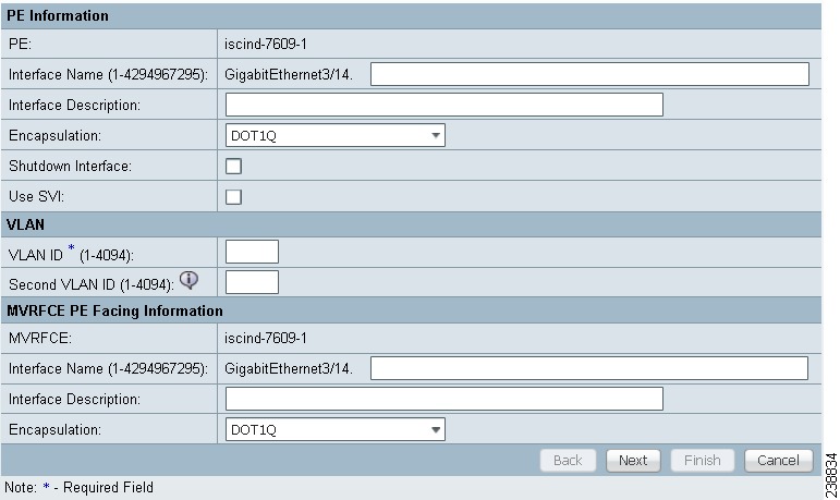
The MPLS Link Attribute Editor - Interface window appears, as shown in Figure 26-6.
Figure 26-6 MPLS Link Attribute Editor - Interface
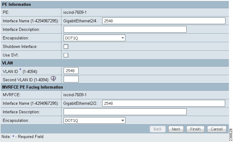
PE Information
Step 12 ![]() Encapsulation: Choose the PE Encapsulation from the drop-down list. (DOT1Q)
Encapsulation: Choose the PE Encapsulation from the drop-down list. (DOT1Q)
Step 13 ![]() VLAN ID: Enter the PE VLAN ID.
VLAN ID: Enter the PE VLAN ID.
MVRFCE PE Facing Information
Step 14 ![]() Encapsulation: Choose the PE Encapsulation from the drop-down list. (DOT1Q))
Encapsulation: Choose the PE Encapsulation from the drop-down list. (DOT1Q))
Step 15 ![]() Click Next.
Click Next.
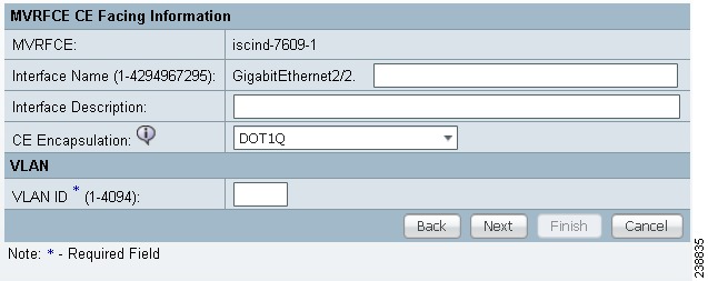
The MPLS Link Attribute Editor - Interface window appears, as shown in Figure 26-7.
Figure 26-7 MPLS Link Attribute Editor - Interface
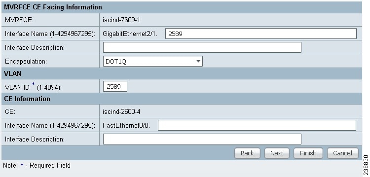
MVRFCE CE Information
Step 16 ![]() Encapsulation: Choose the PE Encapsulation from the drop-down list. (DOT1Q)
Encapsulation: Choose the PE Encapsulation from the drop-down list. (DOT1Q)
Step 17 ![]() VLAN ID: Enter the PE VLAN ID.
VLAN ID: Enter the PE VLAN ID.
MVRFCE PE-Facing Information
Step 18 ![]() Encapsulation: Choose the PE Encapsulation from the drop-down list. (DOT1Q)
Encapsulation: Choose the PE Encapsulation from the drop-down list. (DOT1Q)
Step 19 ![]() Click Next.
Click Next.
The MPLS Link Attribute Editor - IP Address Scheme window appears for PE-MVRF-CE interface address/mask.
Step 20 ![]() Accept the defaults and click Next.
Accept the defaults and click Next.
The MPLS Link Attribute Editor - IP Address Scheme window appears for MVRFCE-CE interface address/mask.
Step 21 ![]() Accept the defaults and click Next.
Accept the defaults and click Next.
The MPLS Link Attribute Editor - Routing Information window reappears for PE-MVRF-CE routing information.
Note ![]() For information about protocol types, see Chapter 24, "Specifying the Routing Protocol for a Service".
For information about protocol types, see Chapter 24, "Specifying the Routing Protocol for a Service".
Step 22 ![]() Accept the defaults and click Next.
Accept the defaults and click Next.
The MPLS Link Attribute Editor - Routing Information window reappears for MVRFCE-CE routing information.
Step 23 ![]() Accept the defaults and click Next.
Accept the defaults and click Next.
The MPLS Link Attribute Editor - VRF and VPN window appears.
Note ![]() For more information on setting the VRF and VPN attributes in MPLS VPN service requests, see Chapter 25, "Defining VRF and VPN Attributes in an MPLS Service Request".
For more information on setting the VRF and VPN attributes in MPLS VPN service requests, see Chapter 25, "Defining VRF and VPN Attributes in an MPLS Service Request".
Step 24 ![]() Click Add to join a VPN.
Click Add to join a VPN.
The Select CERCs window appears.
Step 25 ![]() Choose a Customer from the drop-down list.
Choose a Customer from the drop-down list.
Step 26 ![]() Choose a VPN from the drop-down list.
Choose a VPN from the drop-down list.
Step 27 ![]() Check to choose a VPN from the list.
Check to choose a VPN from the list.
Step 28 ![]() Click Join As Hub or Join As Spoke.
Click Join As Hub or Join As Spoke.
Step 29 ![]() Click Done.
Click Done.
The MPLS Link Attribute Editor - VRF and VPN window reappears.
Step 30 ![]() Click the Next button to associate templates or data files to the service request.
Click the Next button to associate templates or data files to the service request.
Note ![]() This step assumes the policy on which the service request is based has template association enabled. If not, there will be no Next button visible in the GUI. In that case, click Finish and return to the MPLS Service Request Editor window and proceed with Step 34, below.
This step assumes the policy on which the service request is based has template association enabled. If not, there will be no Next button visible in the GUI. In that case, click Finish and return to the MPLS Service Request Editor window and proceed with Step 34, below.
The MPLS Link Attribute Editor - Template Association window appears. In this window, you can associate templates and data files with a device by clicking the Add button in Template/Data File column for the device. When you click the Add button, the Add/Remove Templates window appears. For instructions about associating templates with service requests and how to use the features in this window, see Chapter 49, "Using Templates and Data Files with Policies and Service Requests"
Step 31 ![]() When you have completed setting up templates and data files for any device(s), click Finish in the Template Association window to close it and return to the MPLS Service Request Editor window.
When you have completed setting up templates and data files for any device(s), click Finish in the Template Association window to close it and return to the MPLS Service Request Editor window.
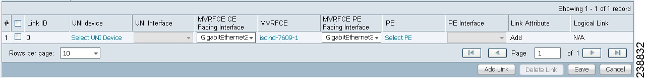
The MPLS Service Request Editor window reappears, as shown in Figure 26-8.
Figure 26-8 MPLS Service Request Editor
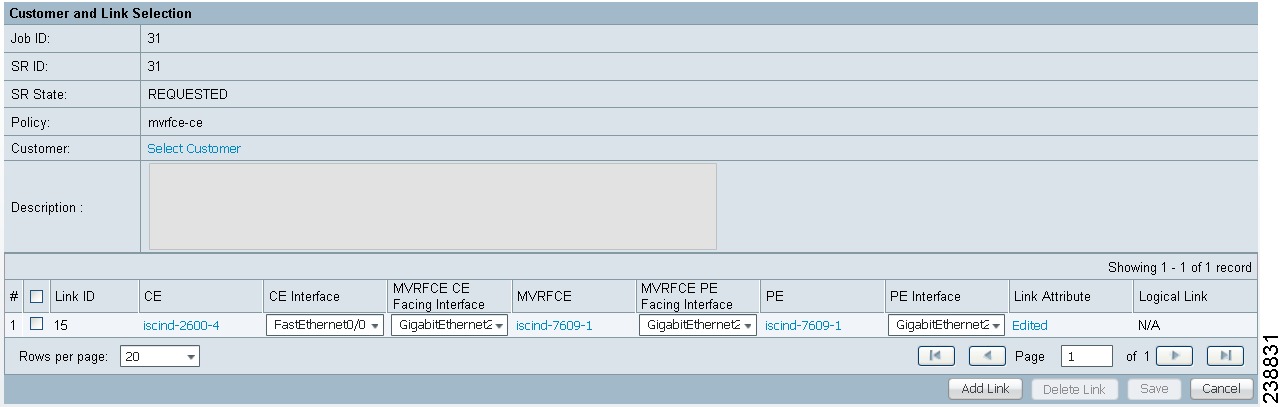
Step 32 ![]() Enter the service request description (mpls-mvrfce-pe-ce) and click Save.
Enter the service request description (mpls-mvrfce-pe-ce) and click Save.
The MPLS Service Requests window reappears showing that the MPLS VPN MVRFCE PE-CE service request is in the Requested state and ready to deploy.
Creating MVRFCE PE-NoCE Service Requests
To create an MVRFCE PE-NoCE service request, perform the following steps.
Step 1 ![]() Choose Operate > Service Requests > MPLS.
Choose Operate > Service Requests > MPLS.
Step 2 ![]() Choose the MPLS Policy (mpls-mvrfce-pe-noce).
Choose the MPLS Policy (mpls-mvrfce-pe-noce).
Step 3 ![]() Click OK.
Click OK.
The MPLS Service Request Editor window appears.
Step 4 ![]() Click Add Link.
Click Add Link.
The MPLS Service Request Editor window appears.
Step 5 ![]() Click Select MVRFCE.
Click Select MVRFCE.
The CPE for MPLS VPN Link window appears.
Step 6 ![]() Choose a MVRFCE and click Select.
Choose a MVRFCE and click Select.
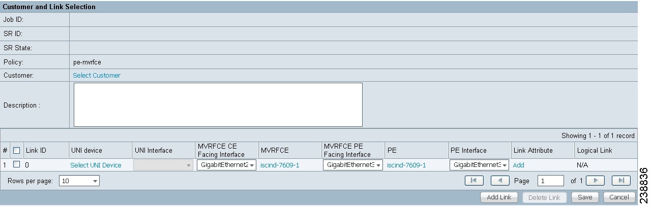
The MPLS Service Request Editor window appears.
Figure 26-9 MPLS Service Request Editor - MVRFCE CE Facing Interface
Step 7 ![]() Choose the MVRFCE CE Facing Interface from the drop-down list.
Choose the MVRFCE CE Facing Interface from the drop-down list.
Step 8 ![]() Click Add in the Link Attribute cell.
Click Add in the Link Attribute cell.
The MPLS Link Attribute Editor - Interface window appears, as shown in Figure 26-10.
Figure 26-10 MPLS Link Attribute Editor - Interface
PE Information
Step 9 ![]() Encapsulation: Choose the PE Encapsulation from the drop-down list. (DOT1Q)
Encapsulation: Choose the PE Encapsulation from the drop-down list. (DOT1Q)
Step 10 ![]() VLAN ID: Enter the PE VLAN ID.
VLAN ID: Enter the PE VLAN ID.
MVRFCE PE Facing Information
Step 11 ![]() Encapsulation: Choose the PE Encapsulation from the drop-down list. (DOT1Q))
Encapsulation: Choose the PE Encapsulation from the drop-down list. (DOT1Q))
Step 12 ![]() Click Next.
Click Next.
The MPLS Link Attribute Editor - Interface window appears, as shown in Figure 26-11.
Figure 26-11 MPLS Link Attribute Editor - Interface
MVRFCE CE Information
Step 13 ![]() Encapsulation: Choose the PE Encapsulation from the drop-down list. (DOT1Q)
Encapsulation: Choose the PE Encapsulation from the drop-down list. (DOT1Q)
Step 14 ![]() VLAN ID: Enter the PE VLAN ID.
VLAN ID: Enter the PE VLAN ID.
MVRFCE PE Facing Information
Step 15 ![]() Encapsulation: Choose the PE Encapsulation from the drop-down list. (DOT1Q)
Encapsulation: Choose the PE Encapsulation from the drop-down list. (DOT1Q)
Step 16 ![]() Click Next.
Click Next.
The MPLS Link Attribute Editor - IP Address Scheme window appears for PE-MVRF-CE interface address/mask.
Step 17 ![]() Click Next to accept the defaults.
Click Next to accept the defaults.
The MPLS Link Attribute Editor - IP Address Scheme window appears for MVRFCE-CE interface address/mask.
Step 18 ![]() Click Next to accept the defaults.
Click Next to accept the defaults.
The MPLS Link Attribute Editor - Routing Information window reappears for PE-MVRF-CE routing information.
Note ![]() For information about protocol types, see Chapter 24, "Specifying the Routing Protocol for a Service".
For information about protocol types, see Chapter 24, "Specifying the Routing Protocol for a Service".
Step 19 ![]() Click Next to accept the defaults.
Click Next to accept the defaults.
The MPLS Link Attribute Editor - Routing Information window reappears for MVRFCE-CE routing information.
Step 20 ![]() Click Next to accept the defaults.
Click Next to accept the defaults.
The MPLS Link Attribute Editor - VRF and VPN window appears.
Note ![]() For more information on setting the VRF and VPN attributes in MPLS VPN service requests, see Chapter 25, "Defining VRF and VPN Attributes in an MPLS Service Request".
For more information on setting the VRF and VPN attributes in MPLS VPN service requests, see Chapter 25, "Defining VRF and VPN Attributes in an MPLS Service Request".
Step 21 ![]() Click Add to join a VPN.
Click Add to join a VPN.
The Select CERCs window appears.
Step 22 ![]() Choose a Customer from the drop-down list.
Choose a Customer from the drop-down list.
Step 23 ![]() Choose a VPN from the drop-down list.
Choose a VPN from the drop-down list.
Step 24 ![]() Check to choose a VPN from the list.
Check to choose a VPN from the list.
Step 25 ![]() Click Join As Hub or Join As Spoke.
Click Join As Hub or Join As Spoke.
Step 26 ![]() Click Done.
Click Done.
The MPLS Link Attribute Editor - VRF and VPN window reappears.
Note ![]() For more information on setting the VRF and VPN attributes in MPLS VPN service requests, see Chapter 25, "Defining VRF and VPN Attributes in an MPLS Service Request".
For more information on setting the VRF and VPN attributes in MPLS VPN service requests, see Chapter 25, "Defining VRF and VPN Attributes in an MPLS Service Request".
Step 27 ![]() Click the Next button to associate templates or data files to the service request.
Click the Next button to associate templates or data files to the service request.
Note ![]() This step assumes the policy on which the service request is based has template association enabled. If not, there will be no Next button visible in the GUI. In that case, click Finish and return to the MPLS Service Request Editor window and proceed with Step 34, below.
This step assumes the policy on which the service request is based has template association enabled. If not, there will be no Next button visible in the GUI. In that case, click Finish and return to the MPLS Service Request Editor window and proceed with Step 34, below.
The MPLS Link Attribute Editor - Template Association window appears. In this window, you can associate templates and data files with a device by clicking the Add button in Template/Data File column for the device. When you click the Add button, the Add/Remove Templates window appears. For instructions about associating templates with service requests and how to use the features in this window, see Chapter 49, "Using Templates and Data Files with Policies and Service Requests"
Step 28 ![]() When you have completed setting up templates and data files for any device(s), click Finish in the Template Association window to close it and return to the MPLS Service Request Editor window.
When you have completed setting up templates and data files for any device(s), click Finish in the Template Association window to close it and return to the MPLS Service Request Editor window.
The MPLS Service Request Editor window reappears, as shown in Figure 26-12.
Figure 26-12 MPLS Service Request Editor
Step 29 ![]() Enter the service request description and click Save. (mpls-mvrfce-pe-noce)
Enter the service request description and click Save. (mpls-mvrfce-pe-noce)
The MPLS Service Requests window reappears showing that the MPLS VPN MVRFCE PE-NoCE service request is in the Requested state and ready to deploy.
Creating an Unmanaged MVRFCE
The unmanaged MVRFCE feature is similar to the unmanaged CE feature in so far as the service provider does not use Prime Fulfillment to upload or download configurations to the CPE. This feature is similar to the managed MVRFCE feature in so far as Prime Fulfillment creates a link with three devices: a PE, an MVRFCE, and a CE.
In the unmanaged scenarios, the customer configures the CPE manually. To automate the process of configuring the unmanaged MVRFCE, the service provider can use Prime Fulfillment to generate the configuration and then send it to the customer for manual implementation.
Figure 26-13 shows an overview of a network topology with MPLS VPN MVRFCE PE-CE links.
Figure 26-13 Unmanaged MVRFCE PE-CE Network Topology
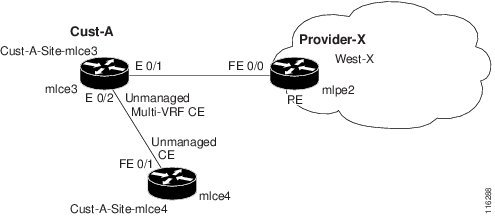
The network topology in Figure 26-13 shows a service provider (Provider-X) and a customer (Cust-A). The Provider contains one Region (West-X) and one PE (mlpe2). The Customer contains an MVRFCE (mlce3) and a CE (mlce4). Both of these CPEs are unmanaged.
 Feedback