- About This Book
-
- Getting Started
- Setting Up the Prime Fulfillment Services for L2VPN
- Creating a FlexUNI/EVC Ethernet Policy
- Creating a FlexUNI/EVC Ethernet Service Request
- Creating a FlexUNI/EVC ATM-Ethernet Interworking Policy
- Creating a FlexUNI/EVC ATM-Ethernet Interworking Service Request
- Creating an L2VPN Policy
- Creating an L2VPN Service Request
- Creating a VPLS Policy
- Creating a VPLS Service Request
- Deploying, Monitoring, and Auditing Service Requests
- Using Auto Discovery for L2 Services
- Sample Configlets
- Setting Up VLAN Translation
-
- Getting Started with MPLS VPN
- Setting Up the Prime Fulfillment Services
- Independent VRF Management
- IPv6 and 6VPE Support in MPLS VPN
- MPLS VPN Service Policies
- MPLS VPN Service Requests
- Provisioning Regular PE-CE Links
- Provisioning Multi-VRFCE PE-CE Links
- Provisioning Management VPN
- Provisioning Cable Services
- Provisioning Carrier Supporting Carrier
- Provisioning Multiple Devices
- Spanning Multiple Autonomous Systems
- Sample Configlets
- Troubleshooting MPLS VPNs
Cisco Prime Fulfillment User Guide 6.1
Bias-Free Language
The documentation set for this product strives to use bias-free language. For the purposes of this documentation set, bias-free is defined as language that does not imply discrimination based on age, disability, gender, racial identity, ethnic identity, sexual orientation, socioeconomic status, and intersectionality. Exceptions may be present in the documentation due to language that is hardcoded in the user interfaces of the product software, language used based on RFP documentation, or language that is used by a referenced third-party product. Learn more about how Cisco is using Inclusive Language.
- Updated:
- March 20, 2015
Chapter: Provisioning Multiple Devices
Provisioning Multiple Devices
This chapter describes how to configure multiple devices, Layer 2 (L2) "switches" and Layer 3 (L3) "routers," using the Prime Fulfillment provisioning process. It contains the following sections:
NPC Ring Topology
This section describes how to create a Ring Topology, connect the CE starting and PE-POP ending points, and configure the Named Physical Circuits (NPC) from end to end, using the Prime Fulfillment provisioning process.
This section contains the following sections:
•![]() Creating Ring of Three PE-CLEs
Creating Ring of Three PE-CLEs
•![]() Configuring NPC Ring Topology
Configuring NPC Ring Topology
Ring Topology Overview
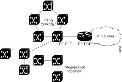
Service providers are now looking to offer L2 and L3 services that must integrate with a common MPLS infrastructure. Prime Fulfillment supports two basic L2 topologies to access L3 MPLS networks:
•![]() Ring Topology
Ring Topology
•![]() Aggregation Topology ("Hub and Spoke")
Aggregation Topology ("Hub and Spoke")
Figure 31-1 shows an example of these two basic L2 access topologies.
Figure 31-1 L2 Access Topologies
Creating Ring of Three PE-CLEs
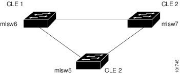
In its simplest form, the Ring Topology is a tripartite structure that comprises at least three PE- CLE. A PE-POP and a Multi-VRF CE can also be part of a Ring.
Figure 31-2 shows an example ring of three Catalyst 3550 switches: mlsw5, mlsw6, and mlsw7.
Figure 31-2 A Ring of Three PE-CLE
To create a ring of three PE-CLEs, perform the following steps.
Step 1 ![]() Choose Inventory > Logical Inventory > Physical Rings.
Choose Inventory > Logical Inventory > Physical Rings.
The Physical Rings window appears.
Step 2 ![]() Click Create to continue.
Click Create to continue.
The Create Ring window appears.
Step 3 ![]() Click Select source device in the first cell.
Click Select source device in the first cell.
The Show Devices window appears, as shown in Figure 31-3.

Note ![]() The Show Devices drop-down window in Figure 31-3 should show CLE rather than PE. This is a known application error. You cannot initiate this process with a PE-POP or a CE. You must begin with a PE-CLE.
The Show Devices drop-down window in Figure 31-3 should show CLE rather than PE. This is a known application error. You cannot initiate this process with a PE-POP or a CE. You must begin with a PE-CLE.
Figure 31-3 Show Devices
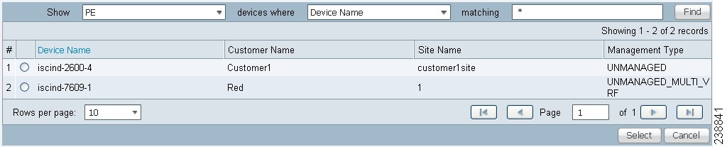
Step 4 ![]() To search for a specific CLE, enter the source device in the matching dialog-box and click Find.
To search for a specific CLE, enter the source device in the matching dialog-box and click Find.
Step 5 ![]() Choose the CLE and click Select.
Choose the CLE and click Select.
The Create Ring window appears, as shown in Figure 31-4.
Figure 31-4 Create Ring
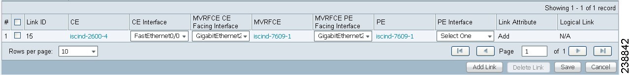
Step 6 ![]() Continue from left to right and from top to bottom to fill the table with the appropriate Device and Interface information, which would be based on a network diagram from your own environment.
Continue from left to right and from top to bottom to fill the table with the appropriate Device and Interface information, which would be based on a network diagram from your own environment.
Note ![]() If you had used the network diagram in Figure 31-6 to populate the Create Ring table, it would contain the above information at the end of this process.
If you had used the network diagram in Figure 31-6 to populate the Create Ring table, it would contain the above information at the end of this process.
Step 7 ![]() Click Save to save your ring in the Repository.
Click Save to save your ring in the Repository.
The NPC Rings window appears, as shown in Figure 31-5
Figure 31-5 NPC Rings

Proceed to Configuring NPC Ring Topology.
Configuring NPC Ring Topology
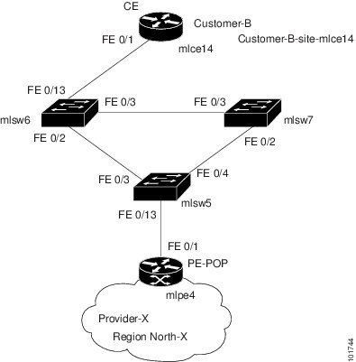
Figure 31-6 shows an example of the Ring Topology (three CLE) inserted between a CE (mlce14) and a PE-POP (mlpe4).
Figure 31-6 The Ring Topology
To configure end-to-end connectivity (CE > Ring (PE-CLE) > PE), perform the following steps.
Step 1 ![]() Choose Inventory > Logical Inventory > Named Physical Circuits.
Choose Inventory > Logical Inventory > Named Physical Circuits.
The Named Physical Circuits window appears.
Step 2 ![]() Click Create.
Click Create.
The Create Named Physical Circuit window appears.
Step 3 ![]() Click Add Device.
Click Add Device.
The Select Devices window appears.
Step 4 ![]() Choose the CE and then click Select.
Choose the CE and then click Select.
The Create Named Physical Circuit window appears.
Step 5 ![]() Click Add Device.
Click Add Device.
The Select Devices window appears.
Step 6 ![]() Choose the PE and then click Select.
Choose the PE and then click Select.
The Create Named Physical Circuit window appears.
Step 7 ![]() Click Insert Ring.
Click Insert Ring.
The Show NPC Rings window appears.
Step 8 ![]() Choose an NPC Ring and click Select.
Choose an NPC Ring and click Select.
The Create a Named Physical Circuit window appears
Step 9 ![]() Choose a device with an available check box and click Select device.
Choose a device with an available check box and click Select device.
The Select a device from ring window appears.
Step 10 ![]() Choose a PE-CLE and click Select.
Choose a PE-CLE and click Select.
The Create Named Physical Circuit window appears.
Step 11 ![]() Choose the incoming and outgoing interfaces for the CE, CLE, and PE until complete.
Choose the incoming and outgoing interfaces for the CE, CLE, and PE until complete.
Step 12 ![]() Choose the remaining device with the darkened check box.
Choose the remaining device with the darkened check box.
The Create a Named Physical Circuit window appears.
Step 13 ![]() Click Save.
Click Save.
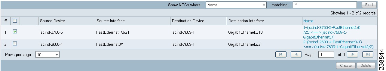
The Named Physical Interfaces window appears, with the Ring Topology displayed, as shown in Figure 31-7.
Figure 31-7 Named Physical Circuits
Ethernet-To-The-Home (ETTH)
This section describes how to configure Ethernet-To-The-Home (ETTH) using the Prime Fulfillment provisioning process.
ETTH is part of the Cisco ETTx solution, which contains both ETTH and Ethernet-to-the-Business (ETTB). ETTB is supported in Prime Fulfillment with the L2VPN Metro Ethernet service feature. Unlike ETTB, whose customers are mainly business customers, ETTH is targeted at residential customers.
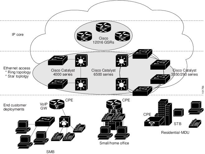
Figure 31-8 shows an overview of the Cisco ETTx solution.
Figure 31-8 Cisco ETTx Solution
From a provisioning standpoint, the main difference between ETTB and ETTH is the consideration of resource scalability. For example, with ETTB, each business customer is allocated one or more VLAN(s).
With ETTH, it is not practical to assign a unique VLAN to each residential customer. The practical solution is to have all, or a group of residential customers, share the same VLAN and use common technology, such as a private VLAN (PVLAN) or a protected port, to guarantee traffic isolation.
Another difference between ETTB and ETTH is that most of the ETTB customers use an Ethernet trunk port while ETTH customers use an access port. In Prime Fulfillment, the access port is fully supported, with CE present or with no CE.
ETTH needs to support multicast based services, such as video, on a shared media such as a ring. Typically, Internet Group Management Protocol (IGMP) with Multicast VLAN Registration (MVR) would be the technology used to support these services.
Access Domain Management
To provide more flexibility in managing an access domain, you can define a management VLAN. Once defined, the management VLAN is used to construct the list of VLANs allowed on the trunk port for all non-UNI ports.
You can also specify how the VLAN allowed list is constructed in a trunk port for a domain, if the list is not on the device. This feature is implemented for L2VPN DCPL parameter. It is available for Layer 2 access to MPLS VPN as well.
As a part of Layer 2 access management, Prime Fulfillment provides the ability to create MAC access lists by specifying the MAC addresses to be allowed or blocked.
Prime Fulfillment ETTH Implementation
The Prime Fulfillment MPLS VPN implementation of ETTH consists of the following three subfeatures:
PVLAN or Protected Port
This feature is used to isolate traffic within a PVLAN. It prevents traffic from flowing between two UNIs.
•![]() PVLAN is only supported on the Catalyst 4500/6500 switches and Cisco 7600 router.
PVLAN is only supported on the Catalyst 4500/6500 switches and Cisco 7600 router.
•![]() Protected Port is only supported on the Catalyst 2950/3550 switches.
Protected Port is only supported on the Catalyst 2950/3550 switches.
Access Port
In Prime Fulfillment, the untagged Ethernet default is supported in the CE present and no CE scenarios. You can choose between two encapsulations: DOT1Q and Default.
The Default encapsulation only indicates that the traffic coming in from the CE is untagged. The UNI, which is always a dot1q port, puts a tag on it before transmitting it. UNI has two options to handle this untagged traffic. It functions as an access port or a trunk port. For this reason, the GUI adds one more item for you to choose.
IGMP with MVR
This feature applies to a very specific user service and network topology. It is used for multicast video on a hub and spoke or ring network. However, it is not up to Prime Fulfillment to decide when it is used. Prime Fulfillment only makes it available and the network application running above Prime Fulfillment must invoke it when needed.
Creating an ETTH Policy
To configure a policy to support ETTH, perform the following steps.
Step 1 ![]() Choose Service Design > Policies > Policy Manager.
Choose Service Design > Policies > Policy Manager.
Step 2 ![]() From the Policy Manager window, choose a Service Policy and click Edit.
From the Policy Manager window, choose a Service Policy and click Edit.
Step 3 ![]() From the Policy Type Information window, click Next.
From the Policy Type Information window, click Next.
The MPLS Policy Editor - Interface window appears, as shown in Figure 31-9.
Figure 31-9 MPLS Policy Editor - Interface
Step 4 ![]() To enable ETTH, check the ETTH Support check box.
To enable ETTH, check the ETTH Support check box.
The ETTH UNI Information check boxes appear between the ETTH Support check box and the CE Information, as shown in Figure 31-10.
Figure 31-10 ETTH UNI Information
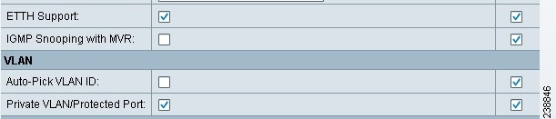
Step 5 ![]() To enable Private VLAN or Protected Port, check the Private VLAN/Protected Port check box.
To enable Private VLAN or Protected Port, check the Private VLAN/Protected Port check box.
Step 6 ![]() To enable IGMP Snooping with MVR, check the IGMP Snooping with MVR check box.
To enable IGMP Snooping with MVR, check the IGMP Snooping with MVR check box.
Three new UNI Information options appear, as shown in Figure 31-11.
Figure 31-11 ETTH UNI Information Options
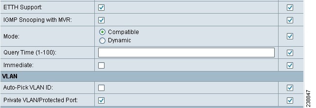
Step 7 ![]() Choose UNI Information options:
Choose UNI Information options:
•![]() Mode
Mode
–![]() Compatible—Multicast addresses are statically configured on the device.
Compatible—Multicast addresses are statically configured on the device.
–![]() Dynamic—IGMP snooping is configured on the device.
Dynamic—IGMP snooping is configured on the device.
•![]() Query Time—Determines how often the device is queried for membership.
Query Time—Determines how often the device is queried for membership.
•![]() Immediate—Removes the interface from the forwarding table immediately, when the session ends.
Immediate—Removes the interface from the forwarding table immediately, when the session ends.
Step 8 ![]() Complete the standard steps and click Save.
Complete the standard steps and click Save.
Creating a Service Request for ETTH
To create a service request for ETTH, perform the following steps.
Step 1 ![]() Choose Operate > Service Requests > Service Request Manager.
Choose Operate > Service Requests > Service Request Manager.
Step 2 ![]() From the Service Requests Manager window, choose a Service Request and click Edit.
From the Service Requests Manager window, choose a Service Request and click Edit.
Step 3 ![]() From the MPLS Service Request Editor window, click Edited from the Link Attribute link.
From the MPLS Service Request Editor window, click Edited from the Link Attribute link.
The MPLS Link Attribute Editor - Interface window appears, as shown in Figure 31-12.
Figure 31-12 MPLS Link Attribute Editor - Interface
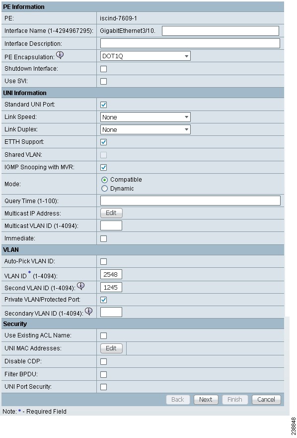
Step 4 ![]() Edit the following Link Attribute specific UNI Information:
Edit the following Link Attribute specific UNI Information:
•![]() Secondary VLAN ID—Enter a VLAN ID for the Private VLAN, which is supported only on the Catalyst 4000 switch.
Secondary VLAN ID—Enter a VLAN ID for the Private VLAN, which is supported only on the Catalyst 4000 switch.
•![]() Multicast IP Address—See Step 5.
Multicast IP Address—See Step 5.
•![]() Multicast VLAN ID—Enter a VLAN ID for the Multicast VLAN.
Multicast VLAN ID—Enter a VLAN ID for the Multicast VLAN.
Step 5 ![]() Click Edit.
Click Edit.
The Multicast IP Addresses dialog box appears.
Step 6 ![]() Edit the following Link Attribute specific UNI Information:
Edit the following Link Attribute specific UNI Information:
•![]() Multicast IP Address—Enter an IP Address for the join the multicast group, which allows users to have access to video on demand, for example.
Multicast IP Address—Enter an IP Address for the join the multicast group, which allows users to have access to video on demand, for example.
•![]() Counter—Enter a count to determine the number of contiguous IP addresses starting with the Multicast IP Address.
Counter—Enter a count to determine the number of contiguous IP addresses starting with the Multicast IP Address.
Step 7 ![]() Click OK.
Click OK.
Step 8 ![]() Complete the standard steps for creating a service request, and click Save.
Complete the standard steps for creating a service request, and click Save.
Note ![]() For more information on setting the VRF and VPN attributes in MPLS VPN service requests, see Chapter 25, "Defining VRF and VPN Attributes in an MPLS Service Request".
For more information on setting the VRF and VPN attributes in MPLS VPN service requests, see Chapter 25, "Defining VRF and VPN Attributes in an MPLS Service Request".
The MPLS Service Requests window reappears showing that the service request is in the Requested state and ready to deploy.
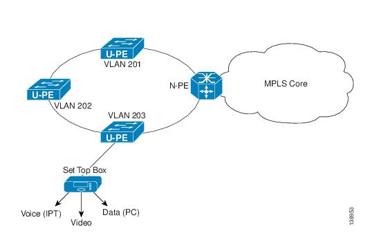
Residential Service
A group of residential customers can share the same VLAN on the same UNI switch with traffic isolation on different UNI interfaces. On an N-PE, a VRF SVI is defined for all the residential services from the same UNI switch, as shown in Figure 31-13.
Figure 31-13 Residential Services
Creating a Policy for Residential Services Over Shared VLAN
A special policy must be created by enabling Shared VLAN. To do this, perform the following steps.
Step 1 ![]() Choose Operate > Service Requests > MPLS.
Choose Operate > Service Requests > MPLS.
The MPLS Policy Editor - Policy Type window appears, as shown in Figure 31-14.
Figure 31-14 Policy Type
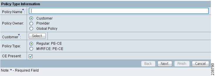
Step 2 ![]() In the Policy Name field, enter a policy name.
In the Policy Name field, enter a policy name.
Step 3 ![]() Under Policy Owner, click the Global Policy radio button.
Under Policy Owner, click the Global Policy radio button.
Step 4 ![]() Under Policy Type accept Regular: PE-CE.
Under Policy Type accept Regular: PE-CE.
Step 5 ![]() Under CE Present, uncheck the check box, then click Next.
Under CE Present, uncheck the check box, then click Next.
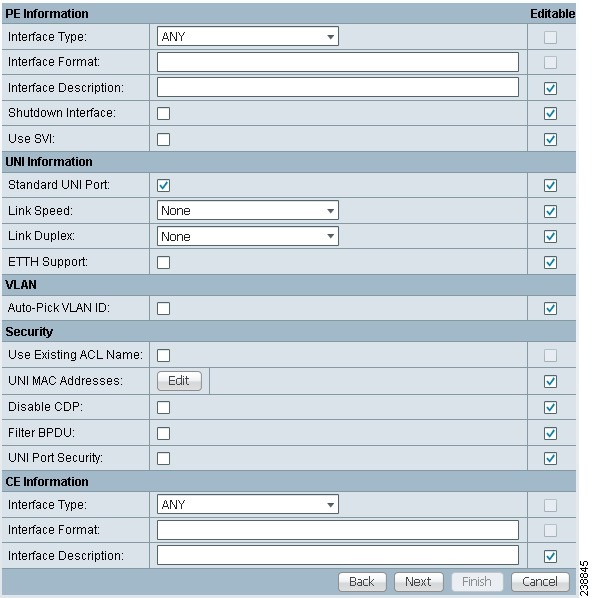
The MPLS Policy Editor - Interface window appears, as shown in Figure 31-15.
Figure 31-15 Interface Settings
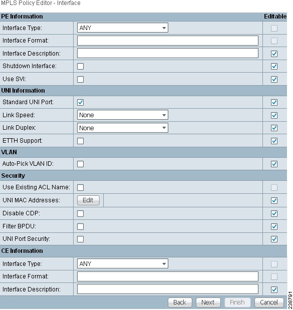
Step 6 ![]() Check the Use SVI: check box, then wait for the window to refresh.
Check the Use SVI: check box, then wait for the window to refresh.
Step 7 ![]() Check the ETTH Support: check box, then wait for the window to refresh.
Check the ETTH Support: check box, then wait for the window to refresh.
Step 8 ![]() Check the Standard UNI Port: check box, then wait for the window to refresh.
Check the Standard UNI Port: check box, then wait for the window to refresh.
Step 9 ![]() Check the Shared VLAN: check box, then wait for the window to refresh. Some fields are now grayed-out.
Check the Shared VLAN: check box, then wait for the window to refresh. Some fields are now grayed-out.
Note ![]() Because this policy enables ETTH Support and Shared VLAN, these attributes become unavailable at the link level.
Because this policy enables ETTH Support and Shared VLAN, these attributes become unavailable at the link level.
Step 10 ![]() Check the Private VLAN/Protected Port: check box, wait for the window to refresh, then click Next.
Check the Private VLAN/Protected Port: check box, wait for the window to refresh, then click Next.
Step 11 ![]() In the IP Address Scheme window, you can continue by clicking Next.
In the IP Address Scheme window, you can continue by clicking Next.
Step 12 ![]() In the Routing Information window, you can continue by clicking Next.
In the Routing Information window, you can continue by clicking Next.
Note ![]() For information about protocol types, see Chapter 24, "Specifying the Routing Protocol for a Service".
For information about protocol types, see Chapter 24, "Specifying the Routing Protocol for a Service".
Step 13 ![]() In the VRF and VPN Member window, you can continue by clicking Next to associate templates, or else finish creating this policy by clicking Finish.
In the VRF and VPN Member window, you can continue by clicking Next to associate templates, or else finish creating this policy by clicking Finish.
Note ![]() For more information on setting the VRF and VPN attributes in MPLS VPN service requests, see Chapter 25, "Defining VRF and VPN Attributes in an MPLS Service Request".
For more information on setting the VRF and VPN attributes in MPLS VPN service requests, see Chapter 25, "Defining VRF and VPN Attributes in an MPLS Service Request".
Creating a Service Request for Residential Services Over Shared VLAN
To create the service request, perform the following steps.
Step 1 ![]() Choose Service Design > Policies > MPLS Policy Editor - Policy Type.
Choose Service Design > Policies > MPLS Policy Editor - Policy Type.
Step 2 ![]() Choose the policy you configured for Shared VLAN Residential Services, then click OK. The MPLS Service Request Editor window appears.
Choose the policy you configured for Shared VLAN Residential Services, then click OK. The MPLS Service Request Editor window appears.
Step 3 ![]() In the MPLS Service Request Editor window, click Add Link, then wait for the window to refresh.
In the MPLS Service Request Editor window, click Add Link, then wait for the window to refresh.
Step 4 ![]() Click the active field Select U-PE.
Click the active field Select U-PE.
Step 5 ![]() Choose a PE device, then click Select.
Choose a PE device, then click Select.
Step 6 ![]() From the active drop-down list, choose an interface, then wait for the window to refresh.
From the active drop-down list, choose an interface, then wait for the window to refresh.
Step 7 ![]() Under Link Attributes column, click the active Add field.
Under Link Attributes column, click the active Add field.
The Interface window appears, as shown in Figure 31-16.
Note ![]() Because the policy created for this feature enables ETTH Support and Shared VLAN, these attributes become unavailable at the link level.
Because the policy created for this feature enables ETTH Support and Shared VLAN, these attributes become unavailable at the link level.
Figure 31-16 Interface Attributes
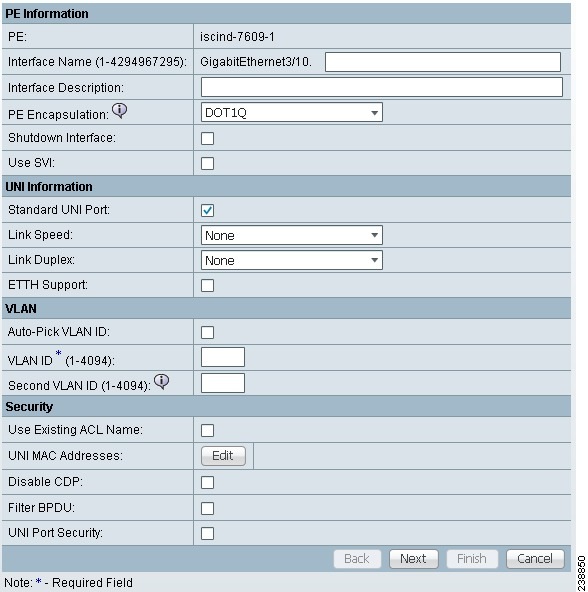
Step 8 ![]() Enter a valid VLAN ID value, then click Next. The IP Address Scheme window appears.
Enter a valid VLAN ID value, then click Next. The IP Address Scheme window appears.
Step 9 ![]() Enter valid values for each required field, then click Next.
Enter valid values for each required field, then click Next.
Step 10 ![]() In the Routing Information widow, check any applicable items, then click Next.
In the Routing Information widow, check any applicable items, then click Next.
Note ![]() For information about protocol types, see Chapter 24, "Specifying the Routing Protocol for a Service".
For information about protocol types, see Chapter 24, "Specifying the Routing Protocol for a Service".
Step 11 ![]() In the VRF and VPN window, for Maximum Route Threshold (required field), accept the default value, or enter a new value.
In the VRF and VPN window, for Maximum Route Threshold (required field), accept the default value, or enter a new value.
Note ![]() If you want to set the VRF and VPN attributes via a previously defined VRF object, check the Use VRF Object check box. For more information on this feature, see Chapter 22, "Independent VRF Management." That chapter describes how to use independent VRF objects in MPLS VPN service policies and service requests.
If you want to set the VRF and VPN attributes via a previously defined VRF object, check the Use VRF Object check box. For more information on this feature, see Chapter 22, "Independent VRF Management." That chapter describes how to use independent VRF objects in MPLS VPN service policies and service requests.
Note ![]() For more information on setting the VRF and VPN attributes in MPLS VPN service requests, see Chapter 25, "Defining VRF and VPN Attributes in an MPLS Service Request".
For more information on setting the VRF and VPN attributes in MPLS VPN service requests, see Chapter 25, "Defining VRF and VPN Attributes in an MPLS Service Request".
Step 12 ![]() Under VPN Selection (required), click Add.
Under VPN Selection (required), click Add.
Step 13 ![]() From the CERC window, choose the desired PE VPN Membership, then click Done.
From the CERC window, choose the desired PE VPN Membership, then click Done.
Step 14 ![]() Back in the VRF and VPN window, click Finish.
Back in the VRF and VPN window, click Finish.
Note ![]() If the policy on which the service request is based has template association enabled, a Next button is visible in the GUI. Click the Next button to add templates and data files to the devices defined in the service request. For instructions about associating templates with service requests, see Chapter 49, "Using Templates and Data Files with Policies and Service Requests"
If the policy on which the service request is based has template association enabled, a Next button is visible in the GUI. Click the Next button to add templates and data files to the devices defined in the service request. For instructions about associating templates with service requests, see Chapter 49, "Using Templates and Data Files with Policies and Service Requests"
When you are finished setting the attributes for the service policy, the MPLS Service Request Editor window appears.
Step 15 ![]() Click Save.
Click Save.
The MPLS Service Requests window reappears showing that the service request is in the Requested state and ready to deploy.
 Feedback