Cisco Evolved Programmable Network Manager 2.1.1 User and Administrator Guide
Bias-Free Language
The documentation set for this product strives to use bias-free language. For the purposes of this documentation set, bias-free is defined as language that does not imply discrimination based on age, disability, gender, racial identity, ethnic identity, sexual orientation, socioeconomic status, and intersectionality. Exceptions may be present in the documentation due to language that is hardcoded in the user interfaces of the product software, language used based on RFP documentation, or language that is used by a referenced third-party product. Learn more about how Cisco is using Inclusive Language.
- Updated:
- June 1, 2017
Chapter: View Device Details
- Find Devices
- Get Basic Device Information: Device 360 View
- View a Device's Local Topology from the Device 360 View
- View the Network's Hardware Inventory
- Get Complete Device Information: Device Details Page
- View and Manage Devices Using the Chassis View
- Device Support for the Chassis View in This Release of Cisco EPN Manager
- View Network Element State Information in the Chassis View
- View Mixed Chassis, Multi-Chassis, and Multi-Shelf Devices in the Chassis View
- View Alarms in the Chassis View
- Configure Interfaces from the Chassis View
View Device
Details
The following topics explain how to get more information about your network devices. You can also generate a variety of device reports that provide hardware and software details, CPU and memory utilization, general device health, and so forth. For information on these reports, see Device Reports. For information on inventory collection, see How Often Is Inventory Collected?.
- Find Devices
- Get Basic Device Information: Device 360 View
- View a Device's Local Topology from the Device 360 View
- View the Network's Hardware Inventory
- Get Complete Device Information: Device Details Page
- View and Manage Devices Using the Chassis View
- View Device Ports
- View Device Interfaces
- View Device Modules
- View Environment Information (Power Supplies, Fans)
- View Device Neighbors
- Get More Information About Links
- View Circuits/VCs
- View Satellites
Find Devices
The quickest way to find a device is to use the quick search text boxes displayed at the top of the Network Devices table (Inventory > Device Management > Network Devices). You can enter partial strings for a device name, IP address, or software version, or choose from the values for reachability, admin status, and Inventory Collection. Devices are also organized into device groups, which you can view by choosing Inventory > Device Management > Network Devices and selecting a device type from the Device Group list.
Get Basic Device Information: Device 360 View
The Device 360 view is a pop-up window that provides quick information about a device, its inventory, and its status. This includes device alarms, modules, interfaces, neighbors, and chassis.
The Device 360 view provides general device and performance information at the top of the view, and more detailed interface information in tabs in the lower part of the view. The information the Device 360 view displays depends on the device type and configuration. The Device 360 view provides the following information.
|
Information Provided in Device 360 View |
Description |
|
General information and tools |
Device type, its OS type and version, its last configuration change, and its last inventory collection. Icons convey the status of the device. Using the menus in the top right of the popup window, you can also perform these tasks:
|
|
Performance data |
Charts reflecting various aspects of the device performance. If a device has multiple memory pools, the Device 360 view will display the average utilization for all of the memory pools. If you want to see information about individual memory pools, use the memory utilization dashlets in the Network Summary dashboard. See Network Summary Dashboard Overview. |
|
Alarms tab |
Current alarms for the device, including their severity, status, and the time they were generated. Depending on the alarm source, you can also launch other 360 views from this tab. |
|
Modules tab |
Modules that are configured on the device, including their name, type, state, ports, and location. |
|
Interfaces tab |
Interfaces that are configured on the device, including status information. You can also launch an Interface 360 view for a specific interface. |
|
Neighbors tab |
NEs that are connected to this device through CDP (Cisco Discovery Protocol). If the selected device does not support CDP, this tab is empty. Displayed information includes device type and name, and the local port and device port. To view the neighbors in a popup topology map, choose Actions > Topology from the top right of the Device 360 view (see View a Device's Local Topology from the Device 360 View. |
|
Circuit/VCs tab |
Circuit/VC name, type, customer, status, and creation date for each circuit provisioned on the device. You can also launch a Circuit/VC 360 view for specific circuits/VCs. |
|
Satellites tab |
For Cisco ASR 9000 devices in a cluster configuration, lists a satellite’s name, type, description, status, and IP and MAC addresses. You can also launch a Satellite 360 view for a specific satellite. |
|
Civic Location |
Geographical information about device's location. |
|
Recent Changes |
The last five changes made on the device, classified as: Inventory, Config (Configuration Archive), or SWIM (Software Images). (These are the same types of changes that are displayed when you choose .) |
|
SRRGs |
Lists the Shared Risk Resource Groups (SRRGs) assigned to the device. Click this tab's ? (help) icon to view its legend. For more information about SRRGs, see View and Manage Shared Risk Resource Groups (SRRG) in the Geo Map. |
You can also view a specific device in the topology map by choosing (at the top right of the Device 360 view).
Compare Device Information and Status
From the Comparison View, you can perform a side-by-side comparison of multiple devices, viewing information such as raised alarms, the status of modules, interfaces, and circuits on those devices, and a summary of recent changes that have been made. To compare devices, do the following:
View a Device's Local Topology from the Device 360 View
You can launch a small topology window from the Device 360 view that displays the network topology around a device, up to 3 hops.
View the Network's Hardware Inventory
Use this procedure to view basic hardware information for all devices in the network—the product name, physical location, serial number, manufacture date, and so forth.
| Step 1 | To view device-level information: |
| Step 2 | To view
element-level information, use one of these methods:
|
Get Complete Device Information: Device Details Page
For the most comprehensive information about a device, use the Device Details page. It provides in-depth inventory information and configuration options.
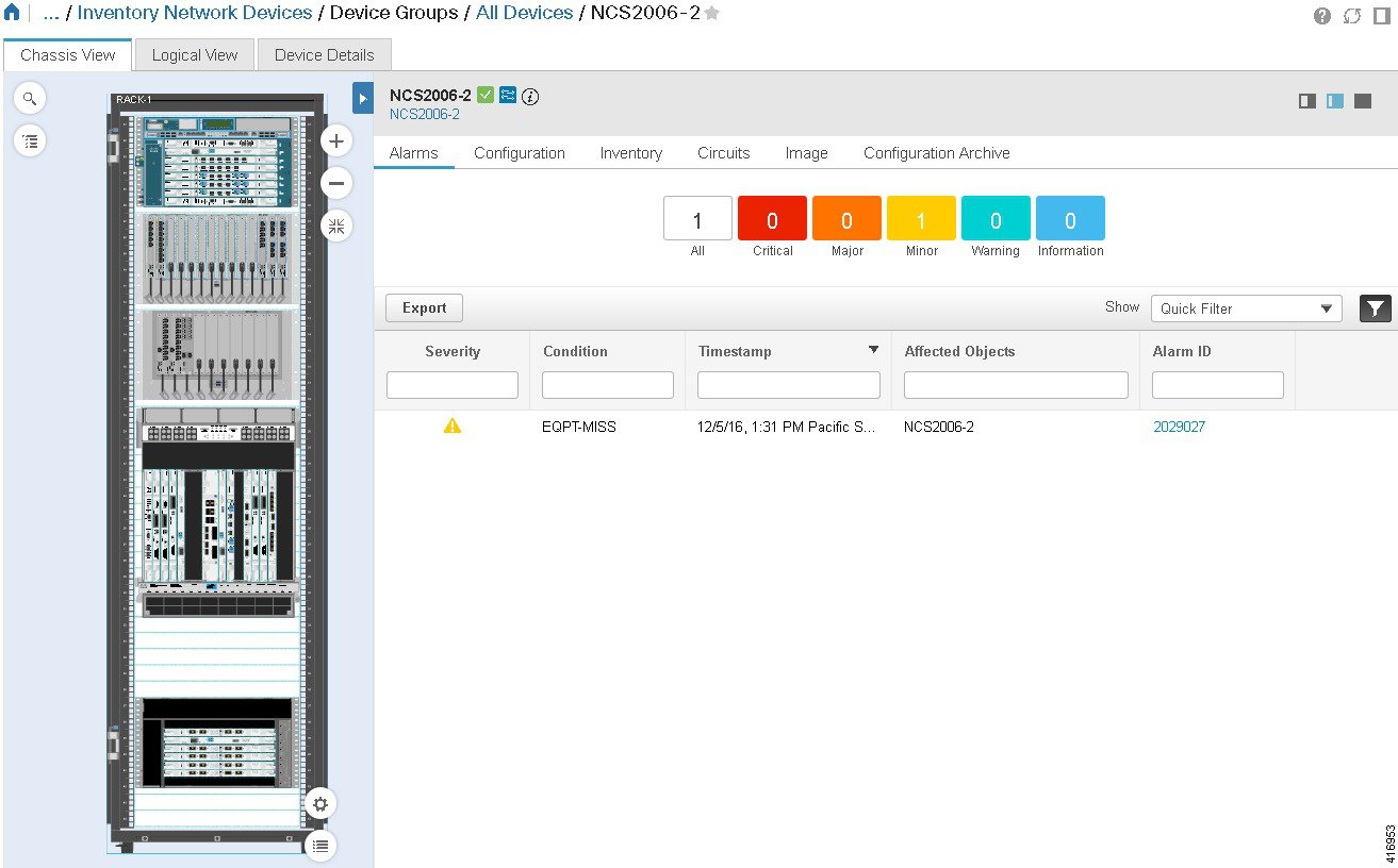
 Note | The Device Details page for Cisco NCS 2000 devices has a different look and feel. For an example and more information, see Device Details Page for Cisco NCS 2000 and Cisco ONS Devices. |
|
To do the following: |
Click this tab in the Device Details page: |
|
View all available inventory information about a device. |
Device Details |
|
Configure interfaces, routing protocols, and other services and technologies. See Ways to Configure Devices Using Cisco Evolved Programmable Network Manager. |
Configuration For Cisco NCS 2000 and Cisco ONS devices, this choice is under the Logical View tab that is at the top of the Device Details page. |
|
View details about changes that were made using a configuration template, and manage future changes. See Ways to Create Configuration Templates Using Cisco EPN Manager. |
Applied/Scheduled Templates (For Cisco NCS 2000 and Cisco ONS devices, this choice has been deprecated.) |
|
Manage the device configuration file that is running on the device, along with files saved in the configuration archive. |
Configuration Archive For Cisco NCS 2000 and Cisco ONS devices, this choice is displayed on the right when you click the Chassis View tab. |
|
Manage the software image that is running on the device, along with images saved in the repository. |
Image For Cisco NCS 2000 and Cisco ONS devices, this choice is displayed on the right when you click the Chassis View tab. |
|
View the device chassis and the status of its elements. (If the Chassis View tab is not displayed, the Chassis View is not supported on the device.) |
Chassis View For Cisco NCS 2000 and Cisco ONS devices, the Chassis View has a different look and feel. For more information, see Overview of the Cisco NCS 2000 and Cisco ONS Chassis View Window. |
To launch the Device Details Page:
Device Details Page for Cisco NCS 2000 and Cisco ONS Devices
The Device Details page for Cisco NCS 2000 and Cisco ONS devices has a different look and feel than the Device Details pages for other device types:
The tabs that are displayed here depend on your selection in the Chassis View:
-
The Image and Configuration Archive tabs are only available when a top-level chassis is selected.
-
The Interfaces and Performance tabs are new to this release. The Performance tab is only available when a card or port is selected.
-
The Applied/Schedule Templates tab is deprecated in this view.
The following table describes the tabs that the Device Details page provides:
|
Tab Name |
Description |
|---|---|
|
Chassis View |
Provides inventory, service, and alarm information that is contextualized to the element you select. Also serves as launch point for configuration, Image management, and Configuration Archive features. (To configure logical elements, click the Logical View tab.) For information on using the Chassis View features, see Overview of the Cisco NCS 2000 and Cisco ONS Chassis View Window. |
|
Logical View |
Provides logical inventory information. Also provides configuration options for logical elements. |
|
Device Details |
Provides system information (environment, modules ports, interfaces, and other settings). |
|
Alarms |
Get information about the alarms that have been raised on a device, a card, or a port. See View an Alarm's Details. |
|
Configuration |
Configure a device, card, or port. Elements are grouped by their physical location. (To configure elements that are grouped according to their logical function, click the Logical View tab.) See Ways to Configure Devices Using Cisco Evolved Programmable Network Manager. |
|
Inventory |
View detailed hardware information such as serial numbers and manufacture dates for a device or card. |
|
Interfaces |
View the status of interfaces configured on a device, card, or port. From here, you can also open the Interface 360 view for a particular interface. For links to topics that describe other ways to view interface information in Cisco EPN Manager, see View Device Interfaces. |
|
Performance |
View summary information and high-level performance metrics for the selected interface on a card or port. The dashlets displayed in addition to the Interface Details dashlet will vary, depending on the interface type you chose. After choosing an interface from the Interface drop-down list, make sure to click Apply in order to refresh the information that is displayed. |
|
Circuits |
View the circuits a device, card, or port participates in. For links to topics that describe other ways to view circuit information in Cisco EPN Manager, see View Circuits/VCs. |
|
Image |
Manage the software image that is running on the device. See View the Images That Are Saved in the Image Repository. |
|
Configuration Archive |
Manage the device configuration file that is running on the device. See View All Archived Files. |
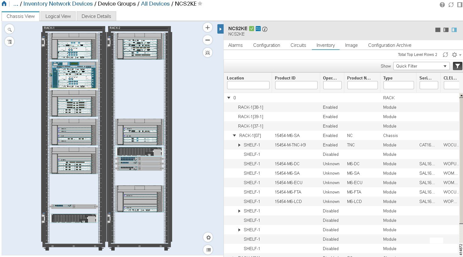
View and Manage Devices Using the Chassis View
Note | The Chassis View for Cisco NCS 2000 and Cisco ONS devices has a new look and feel. For more information, see Overview of the Cisco NCS 2000 and Cisco ONS Chassis View Window. |
The Chassis View provides an interactive model of a device chassis and its hardware elements. From the Chassis View you can:
-
View the contents of a chassis.
-
Check the state of chassis elements and quickly locate problems.
-
View alarmed elements and launch views that provide alarm details.
-
Configure interfaces (using the launch point that opens the Device Details page).
The elements that are displayed in the Chassis View depend on the device type and the elements that are configured on the device.
See these topics for information about how to launch and use the Chassis View:
- Open the Chassis View
- Permissions Required to View and Configure Devices Using the Chassis View
- Overview of the Chassis View Window
- Device Support for the Chassis View in This Release of Cisco EPN Manager
- View Network Element State Information in the Chassis View
- View Mixed Chassis, Multi-Chassis, and Multi-Shelf Devices in the Chassis View
- View Alarms in the Chassis View
- Configure Interfaces from the Chassis View
Open the Chassis View
The following table describes the various ways you can open the Chassis View. If a device does not provide these launch points, it means the device does not support the Chassis View. For a list of devices that support the Chassis View, see Device Support for the Chassis View in This Release of Cisco EPN Manager.
|
To open a Chassis View from: |
Do the following: |
The Chassis View is displayed in: |
||
|---|---|---|---|---|
|
Network Devices table |
Click
|
A pop-up window |
||
|
A full-page view |
||||
|
Device 360 view |
Choose from the top right of the Device 360 view. |
A pop-up window |
||
|
A full-page view |
|||
|
Device Details page |
Click the Chassis View tab.
|
A full-page view |
To open a full-page Chassis View from a Chassis View pop-up window, do one of the following:
Permissions Required to View and Configure Devices Using the Chassis View
-
Full access (read and write)—Users in this group can view and configure devices using the Chassis View.
-
Read-only access—Users in this group can use the Chassis View to view devices but not to configure them.
-
Write-only access—Users in this group can use the Chassis View to configure devices but not view them (only applies to the NBI Write group).
-
No access—Users in this group cannot access or use the Chassis View.
|
Group Type |
|
Read |
Write |
|---|---|---|---|
|
Web UI |
Root |
X |
X |
|
Super Users |
X |
X |
|
|
Admin |
— |
— |
|
|
Config Managers |
X |
X |
|
|
System Monitoring |
X |
— |
|
|
User-Defined 1-4 |
X |
— |
|
|
Monitor Lite |
X |
— |
|
|
NBI |
NBI Credential |
— |
— |
|
NBI Read |
X |
— |
|
|
NBI Write |
— |
X |
|
|
North Bound API |
X |
X |
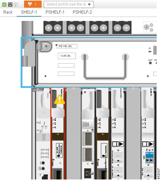
Overview of the Chassis View Window
Note | The Chassis View for Cisco NCS 2000 and Cisco ONS devices has a different look and feel. See Overview of the Cisco NCS 2000 and Cisco ONS Chassis View Window for an example. |
The following
illustration shows a Chassis View for a Cisco NCS 4009. In this example, the
user selected
0/5-PORT-7 from the port search drop-down list above
the Chassis View graphic. The port pulsates in the Chassis View to help the
user locate it (note the concentric yellow circles around the port). When the
user double-clicked the containing line card module, the Chassis View brought
the module to the forefront (and rotated it) for easy viewing. The badges
displayed on the ports indicate the primary status of the port (see
Port and Interface States).
Some elements may be surrounded by colored lines to indicate their state (out
of service, pre-provisioned, and so forth). To open a key that explains the
meaning of the badges and these other indicators, click
![]() at the bottom right of the Chassis View.
at the bottom right of the Chassis View.
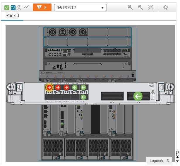
If a device has multiple chasses or shelves, each chassis or shelf is displayed in a separate tab (for an example, see View Mixed Chassis, Multi-Chassis, and Multi-Shelf Devices in the Chassis View). If a card image cannot be retrieved, the Chassis View displays a question mark alongside the card name.
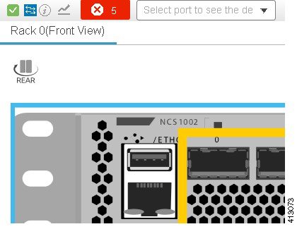
Some devices support front and rear views, as shown in the following example (note the "rear" icon above the Chassis View graphic). Clicking the "rear" icon toggles the image to the front view, and vice versa.
The icons at the top left of the Chassis View provide basic device health information and launch points for tools that can provide more details.
|
Device Information Icon |
Description |
|---|---|
|
|
Device reachability state (see Device Reachability and Admin States). The green check means the device is reachable. |
|
|
Device administrative status (see Device Reachability and Admin States). The blue icon means the device is managed. |
|
|
Launch point for Device 360 view. |
|
Launch point for device performance graphs. The graphs provide CPU and memory utilization data (performance graphs are not supported on Cisco NCS 2000 and Cisco ONS devices). |
|
|
Summary of device alarms (click to open Alarm Summary popup window). |
|
|
|
Device ports search field. Choose a port from the drop-down list or enter a partial string to locate a port (it will blink in the Chassis View). |
|
Front and rear view toggle (currently supported on Cisco NCS 1002, Cisco ASR 901S, and Cisco cBR-8 devices only). |
You can also:
- Enable and disable alarm
pulsating—Click
 at the top right of the Chassis View.
- Zoom in, zoom out, and open
a full-page Chassis View—Use the tools at the top right of the Chassis View.
Clicking
 opens
a full-page Chassis View.
opens
a full-page Chassis View.
- Open a key that explains
the significance of badges and colored lines—Click
 at the bottom right of the Chassis View.
Note | The colors rendered in the Chassis View may not match your physical device because the Chassis View displays a generic image that is packaged with Cisco EPN Manager . |
Overview of the Cisco NCS 2000 and Cisco ONS Chassis View Window
The Chassis View window for Cisco NCS 2000 and Cisco ONS devices has a different look and feel than the Chassis View for other devices. To open this view, use one of the launch points documented in Open the Chassis View.
Note | The colors rendered in the Chassis View may not match your physical device because the Chassis View displays a generic image that is packaged with Cisco EPN Manager. |
The following table describes the Chassis View’s components and their function:
|
Chassis View Component |
Description |
|---|---|
 |
Opens a field you can use to search for a particular rack, shelf, module, or interface on a device. |
 |
Opens the Chassis Explorer. See Chassis Explorer Overview. |
 |
Indicates the device’s reachability state (see Device Reachability and Admin States). This example indicates the device is reachable. |
 |
Indicates the device’s administrative status (see Device Reachability and Admin States). This example indicates the device is managed. |
 |
Opens the device’s Device 360 view. See Get Basic Device Information: Device 360 View. |
| Launch Configuration link | Opens the device’s Device Details page. The tabs displayed on this page will vary, depending on whether a device, module, or port is currently selected in the Chassis View. See Device Details Page for Cisco NCS 2000 and Cisco ONS Devices. |
 |
Adds a shortcut to the device’s Chassis View in the Dock window. See Customize the Dock Window. |
 |
Closes the Chassis View. |
 |
Zooms in on an image. |
 |
Zooms out from an image. |
 |
Resizes an image so it can be viewed in its entirety within the Chassis View. |
|
Toggles between the front and rear Chassis View for a device. This feature is supported by the following Cisco devices:
|
|
 |
Rotates the image of the module that is currently displayed. This icon is not available when an entire device is displayed. |
 |
Click to access the Enable Alarm Blinking check box. When checked, any alarm badges displayed for a module or port will blink in order to draw attention to them and make them easier to locate. |
 |
Opens a key that explains the significance of badges and colored lines displayed in the Chassis View. |
Chassis Explorer Overview
The Chassis Explorer enhances the functionality of the Chassis View for Cisco NCS 2000 and Cisco ONS devices in a number of ways. To quickly locate a particular module, place your cursor over its listing in the Chassis Explorer and the Chassis View highlights it. Say you want to focus your troubleshooting efforts on a particular shelf. Click its Chassis Explorer listing and the Chassis View updates, displaying only that shelf. When a device's Device Details page is open, click a module's i (information) icon to open a pop-up window that displays summary information for that module and provides links that allow you to reset or delete that card. And if you open the same pop-up window for an empy card slot, it gives you the option to add a new card.
Note | For more information about adding, resetting, and deleting cards, see the following topics: |
By default, the Chassis Explorer opens whenever you open the Chassis View for a Cisco NCS 2000 and Cisco ONS device. If it obscures a Chassis View area you need to look at, click the Chassis Explorer and hold down your mouse while you move it to another location.
Device Support for the Chassis View in This Release of Cisco EPN Manager
The following table lists the Chassis View features and the devices on which they are supported. This means the feature has been tested and verified on that device. While you can launch the Chassis View from other devices, it has only been verified on the devices below.
Note | The Chassis View for Cisco NCS 2000 and Cisco ONS devices has a different look and feel from the Chassis View for all other devices. An example of the Cisco NCS 2000 Chassis View is provided in Overview of the Cisco NCS 2000 and Cisco ONS Chassis View Window. |
|
Feature |
Supported on: |
|
General features |
Cisco NCS 1002 device Cisco NCS 2000 devices Cisco NCS 4000 and 4200 devices Cisco ONS devices Cisco ASR 900 devices Cisco ASR 9000 devices Cisco cBR-8 device |
|
Multi-chassis information |
Cisco NCS 2000 devices Cisco ONS devices Cisco ASR 9000 devices |
|
Operational States |
Cisco NCS 1002 device Cisco NCS 2000 devices Cisco NCS 4000 and 4200 devices Cisco ONS devices Cisco ASR 900 devices Cisco ASR 9000 devices Cisco cBR-8 device |
|
Alarms |
Cisco NCS 1002 device—Port, card, module, equipment alarms Cisco NCS 2000 devices—Port, card, module, equipment alarms Cisco NCS 4000 and 4200 devices—Port alarms Cisco ONS devices Cisco ASR 900 devices—Port, card, module, equipment alarms Cisco ASR 9000 devices—Port, card, module, equipment alarms Cisco cBR-8 device |
View Network Element State Information in the Chassis View
Badges, lines, and colors provide state information about elements and components in a device. To display a key that lists what the badges, lines, and colors mean, click the Legends icon at the bottom right of the Chassis View.
See these topics for more information:Note | Port state information is not shown for the CFP ports on an A9K-400G-DWDM-TR line card as these ports are not yet supported. |
Equipment Operational States (Chassis View)
Equipment Operational State—The equipment operational state represents the running state of the network element.
Port and Interface States
Port/Interface Primary States—A port/interface's primary state conveys the most important state information for a port/interface by combining the admin and operational states. The Multilayer Trace displays either a port primary state or alarm status. For the Chassis View, if an element in the Chassis View does not support changing color to indicate a state change, you can still get the state change information from the alarm that is generated for the state change.
|
Port/Interface Primary State |
Icon |
Admin Status |
Operational State |
|
Unknown |
|
Unknown |
Unknown |
|
Down |
|
Up |
Down |
|
Test |
|
Test |
— |
|
Admin Down |
|
Admin Down |
— |
|
Up |
|
Up |
Up |
|
Auto Up |
|
Up |
Auto Up |
Port/Interface Admin Status—The port/interface admin status represents the configured state of the port or interface (for example, if an administrator has manually shut down a port).
|
Port/Interface Admin Status |
Icon |
Description |
|
Unknown |
|
Port/interface admin status is unknown. There is no response (or insufficient response) from the device. |
|
Admin Down |
|
Port/interface was manually shut down by the administrator. |
|
Up |
|
Port/interface is enabled by administrator. |
|
Test |
|
Port/interface is being tested by the administrator. |
Port/Interface Operational State—A port/interface's operational state conveys the port or interface's running state and whether it is working properly.
|
Port/Interface Operational State |
Icon |
Description |
|
Unknown |
|
Port/interface operational state is unknown. There is no response (or insufficient response) from the device. |
|
Down |
|
Port/interface is not working properly. |
|
Up |
|
Port/interface is receiving and transmitting data. |
|
Auto Up |
|
Port/interface is receiving and transmitting data (only certain devices support this state; other devices use "Up"). |
View Mixed Chassis, Multi-Chassis, and Multi-Shelf Devices in the Chassis View
If a device has multiple shelves or chassis, the Chassis View displays each shelf or chassis on a separate tab. When you select a tab, you can view the details of that specific shelf or chassis. For mixed-chassis, multi-chassis, and multi-shelf devices, Cisco EPN Manager aggregates alarms to a chassis or shelf as explained in View Alarms in the Chassis View.
The following figure shows the Chassis View for a Cisco ASR 9001 device with a Cisco ASR 9000v dedicated satellite device. You can toggle between the Chassis View for the two devices by clicking the tabs at the top of the window. (The Chassis View window for Cisco NCS 2000 and Cisco ONS devices has a different look and feel; see Overview of the Cisco NCS 2000 and Cisco ONS Chassis View Window.)
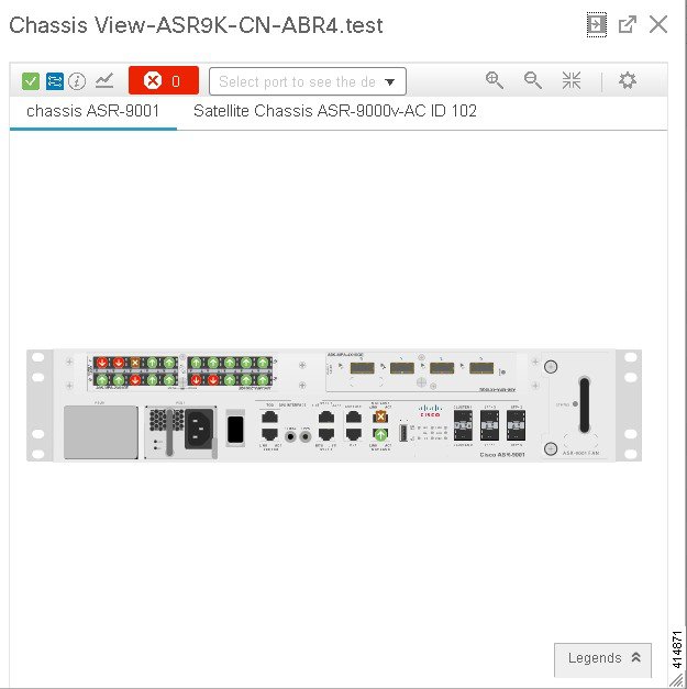
For multi-chassis devices in a cluster, the Device 360 view's Chassis tab identifies which chassis is the primary and which is the backup.
This example shows a mixed Chassis View that has both Cisco NCS 2000 and Cisco ONS 15454 chassis. Shelf numbers are not consecutive because of the different types of chassis.
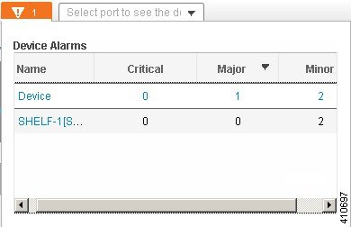
View Alarms in the Chassis View
An alarm badge in the Chassis View represents one or more alarms that have been localized to a piece of equipment. For an element with multiple alarms, the badge icon will convey the most severe alarm. (The Chassis View window for Cisco NCS 2000 and Cisco ONS devices has a different look and feel; see Overview of the Cisco NCS 2000 and Cisco ONS Chassis View Window.)
You can customize
the Chassis View so that alarm icons will blink. Choose
![]() at the top right of the window, then select
Enable
Alarm Blinking.
at the top right of the window, then select
Enable
Alarm Blinking.
The information displayed in a Chassis View Alarm Summary depends on from where you launch the Alarm Summary:
| Launching the Chassis View from here: |
Displays: |
|
Top left of Chassis View window (device information area) |
Alarms on the device. An example Alarm Summary for a multi-shelf device is provided after this table. |
|
Hovering over an alarm badge within the Chassis View |
Alarms aggregated to that piece of equipment. |
When you launch the device Alarm Summary for a multi-chassis, mixed-chassis, or multi-shelf devices, the Alarm Summary shows the total device alarms and the total alarm count for each shelf or chassis.
Note | Launching the Alarm Summary is not supported on Cisco NCS 2000 and Cisco ONS devices. |
Configure Interfaces from the Chassis View
To configure a device interface from the Chassis View, complete one of the following procedures. The procedure you need to complete depends on whether you are using the Chassis View for a Cisco NCS 2000 or Cisco ONS device.
Cisco NCS 2000 and Cisco ONS Devices
| Step 1 | With a device’s Chassis View open, click the Launch Configuration link.
The Device Details page opens. |
| Step 2 | Click the Logical View tab. |
| Step 3 | From the Features pane, choose Interfaces > the interface type you want to configure. |
| Step 4 | Complete the instructions specific to the interface type you chose to add or edit an interface.
For example, if you are adding a new loopback interface, you would complete the instructions described in Configure Loopback Interfaces. |
Non-Cisco NCS 2000 and Cisco ONS Devices
| Step 1 | With a device’s Chassis View open, click the Go to Full Page icon from the top right corner.
The Device Details page opens. | ||
| Step 2 | Click the Configuration tab.
Note the two side tabs: Logical View and Chassis View. | ||
| Step 3 | Click the Chassis View side tab.
The right side of the page updates, displaying the Ethernet table.
| ||
| Step 4 | Do one of the following:
| ||
| Step 5 | Click the zoom tool in the top right corner of the Chassis View to enlarge the image, then locate the module that the interface you want to configure resides on/will reside on. | ||
| Step 6 | Click the port associated with the interface you want to configure.
The attributes for the interfaces already configured on that port are displayed. | ||
| Step 7 | Complete the instructions specific to the interface type you chose to add or edit an interface.
For example, if you are adding an Ethernet interface, follow the instructions in Configure Ethernet Interfaces and Subinterfaces. |
View Device Ports
You can get in-depth information about a device's physical ports from the Device Details page. You can also get basic port information from various 360 views.
To view a device chassis with its modules and ports, use the Chassis View. See Open the Chassis View.
|
To view this port information: |
Do the following: |
|
All Physical ports on a device (including port alias and residing module) |
|
|
An interface's ports |
Check the Interface tab on a 360 view |
|
Ports connected to a module |
Check the Modules tab on a Device 360 view |
|
Ports connected to a neighbor |
Check the Neighbors tab on a Device 360 view |
For a matrix of ports states and icons, see Port and Interface States.
View Device Interfaces
Cisco EPN Manager provides the following ways to view device interfaces:
|
Ways to View Interfaces |
For more information, see: |
|
View details about a specific interface |
|
|
View a specific device's interfaces |
View a Specific Device's Interfaces: Device 360 View Get Comprehensive Information About a Device's Interfaces Using the Device Details Page |
- View a Specific Device's Interfaces: Device 360 View
- Get a Quick Look at a Device Interface: Interface 360 View
- Get Comprehensive Information About a Device's Interfaces Using the Device Details Page
View a Specific Device's Interfaces: Device 360 View
Use the Device 360 view to quickly check the status of a device's interfaces.
Get a Quick Look at a Device Interface: Interface 360 View
The Interface 360 view gives you a quick details about a specified interface. In addition to status, performance, and general interface information, you can enable and disable the interface from the Interface 360 view. The Interfaces 360 view also provides ways to open 360 views for circuits/VCs (depending on the interface configuration).
You can launch the Interface 360 view wherever you see an "i" icon next to an interface name—for example, in an alarms table, or in the various 360 views under the Interfaces or Endpoints tabs.
You can also view a specific interface in the topology map by choosing (at the top right of the Interface 360 view).
The Interface 360 view provides general interface and performance information at the top of the view, and more detailed interface information in tabs in the lower part of the view. The information the Interface 360 view displays depends on the interface configuration.
|
Information Provided in Interface 360 View |
Description |
|
General information |
The interface name, status, description, type, device name; IP address, MAC address, and so forth. Using the menus in the top right of the popup window, you can also perform these tasks:
|
|
Performance data |
Graphs or charts reflecting various aspects of interface performance. |
|
Alarms |
Current alarms for the interface, including their severity, status, and the time they were generated. Also provides a launch point to the Alarm Browser. |
|
Interfaces |
Name, operational and admin status for each associated interface. Also provide a launch point for the Interface 360 view. |
|
Circuit/VCs |
(For interfaces that participate in provisioned circuits) Circuit/VC name, type, customer, status, and creation date. Also provides a launch point for the Circuit/VC 360 view. |
Get Comprehensive Information About a Device's Interfaces Using the Device Details Page
Use the Device Details page to get extensive information about all of the interfaces that are configured on a device. For easier navigation, interfaces are grouped together by type.
View Device Modules
To view device module information, choose Inventory > Device Management > Network Devices, then launch a Device 360 or Device Details page, depending on how much information you want.
|
To get this information: |
Use this navigation: |
|
Basic module information: Status, type, ports |
|
|
Module equipment type and power information |
From the Device Details page, choose System > Modules under the Device Details tab. |
View Environment Information (Power Supplies, Fans)
Environment-related information, such as details about power supplies and fans, is displayed in a device’s Device Details page. To access this information:
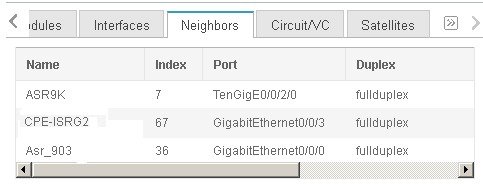
View Device Neighbors
Device neighbor information, such as the neighbor name, port number, index, and duplex setting, is displayed in a device’s Device 360 view.
For example:
Get More Information About Links
Cisco EPN Manager provides a variety of ways that you can view links and get more details about them:
|
To view link information for: |
See the procedures in: |
|
A specific link |
|
|
A specific link in a topology map |
|
|
A group in a topology map |
|
|
All of Cisco EPN Manager |
View Circuits/VCs
Cisco EPN Manager provides a variety of ways that you can view circuits/VCs:
|
To view circuit/VC information for: |
See the procedures in: |
|
A specific circuit/VC in a topology map, in a Circuit/VC 360 view, or in a Circuit/VC Details page |
Get Quick Information About a Circuit/VC: Circuit/VC 360 View Get Comprehensive Information About a Circuit/VC: Circuit/VC Details Window |
|
A device |
|
|
A device group in a topology map or in an expanded table |
|
|
All of Cisco EPN Manager |
View Satellites
Cisco EPN Manager provides the following ways to view satellite information for host-satellite configurations:
|
Ways to View Satellites |
For more information, see: |
|
View all satellites in a location group using a topology map |
View Cisco ASR 9000 Host-Satellite Topologies in the Topology Map |
|
View a specific device's satellites from a Device 360 view |
|
|
View details about a specific satellite, including the hosts it is connected to, using the Satellite 360 view |
 Feedback