Cisco CRS Carrier Routing System Multishelf System Interconnection and Cabling Guide
Bias-Free Language
The documentation set for this product strives to use bias-free language. For the purposes of this documentation set, bias-free is defined as language that does not imply discrimination based on age, disability, gender, racial identity, ethnic identity, sexual orientation, socioeconomic status, and intersectionality. Exceptions may be present in the documentation due to language that is hardcoded in the user interfaces of the product software, language used based on RFP documentation, or language that is used by a referenced third-party product. Learn more about how Cisco is using Inclusive Language.
- Updated:
- November 6, 2016
Chapter: Cabling the Control Network Using 22-Port Shelf Controller Gigabit Ethernet Cards
Cabling the Control
Network Using 22-Port Shelf Controller Gigabit Ethernet Cards
Cabling the Control Network Using 22-Port Shelf Controller Gigabit Ethernet Cards
This chapter describes how to connect cables between two 22-port SCGE cards and the other components of a multishelf system. These connections establish control network connectivity for the multishelf system.
 Note | These procedures are for a new multishelf system installation. If you are converting a Cisco Catalyst-based control network over to a 22-port SCGE card control network, see the Cisco CRS Carrier Routing System Multishelf System Upgrade and Conversion Guide. |
Control Network Cabling
This section describes cabling assignments for various multishelf system configurations. The following sub-sections are included:
The multishelf system is connected between LCC and FCC with four paths per LCC (two per each RP connection). Each of the two paths have Gigabit Ethernet (GE) connections (on each RP) that are connected to two connections on each GE (on the 22-port SCGE cards) in the FCCs. The 22-port SCGE card provides the GE path, or control Ethernet network, between all chassis.
 Caution | A multishelf system will operate with only one 22-port SCGE card installed, but Cisco strongly suggests using two cards for redundancy. If you operate the multishelf system with a single card and that card fails, the multishelf system has no control network connectivity and the router fails. |
Note the following connection tips:
- Any GE ports can be used, in any sequence, but we suggest using ports in sequence as a convention to enable easier maintenance.
- SCGE0 is the 22-port SCGE card in the FCC upper card cage. SCGE1 is the 22-port SCGE card in the FCC lower card cage.
Caution | Do not remove the plugs from the GE optical bores or the fiber-optic cable until you are ready to connect the cable. The plugs protect the bores and cable from contamination. |
- Prerequisites
- Connections for a Single-FCC System
- Connections for a Two-FCC System
- Connections for a Four-FCC System
Prerequisites
- Before cabling the system, install each line card chassis (LCC) and fabric card chassis (FCC) in the planned location.
For information on installing the LCCs and FCCs, see the following documents:
-
- Cisco CRS Carrier Routing System Fabric Card Chassis Installation Guide
- Cisco CRS Carrier Routing System 16-Slot Line Card Chassis Installation Guide
- All connections are made using single-mode LC to LC fiber cables.
-
Determine the required amount of cabling based on the configuration in use:
- Single-FCC system requires 9 cables—8 RP to SCGE cables and 1 mesh cable
- Two-FCC system requires 14 cables—8 RP to SCGE cables and 6 mesh cables
- Four-FCC system requires 36 cables—8 RP to SCGE cables and 28 mesh cables
Connections for a Single-FCC System
The figure below shows the cabling scheme for a single-FCC system. The table below lists the cabling connections that must be completed between the RPs and the 22-port SCGE cards and Table 2 lists the mesh connection in a single-FCC system.
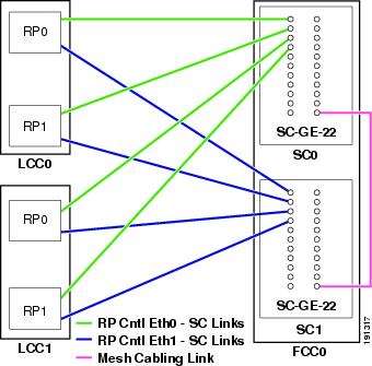
Note that, while Figure 3-1 describes a two-LCC multishelf system, up to eight LCCs can be added to a single FCC multishelf system. The same level of expansion is possible in a two- or four-FCC multishelf system even though Figure 3-3 and Figure 3-5 show two LCCs. Table 3-1 and Table 3-3 map out eight LCCs.
|
From Chassis |
From RP Port |
To 22-Port SCGE Card Number |
To 22-Port SCGE Card Port Number |
|
LCC0 |
RP0, Cntl Eth 0 |
SC0 |
GE0 |
|
RP0, Cntl Eth 1 |
SC1 |
GE0 |
|
|
RP1, Cntl Eth 0 |
SC0 |
GE1 |
|
|
RP1, Cntl Eth 1 |
SC1 |
GE1 |
|
|
LCC1 |
RP0, Cntl Eth 0 |
SC0 |
GE2 |
|
RP0, Cntl Eth 1 |
SC1 |
GE2 |
|
|
RP1, Cntl Eth 0 |
SC0 |
GE3 |
|
|
RP1, Cntl Eth 1 |
SC1 |
GE3 |
|
|
LCC2 |
RP0, Cntl Eth 0 |
SC0 |
GE4 |
|
RP0, Cntl Eth 1 |
SC1 |
GE4 |
|
|
RP1, Cntl Eth 0 |
SC0 |
GE5 |
|
|
RP1, Cntl Eth 1 |
SC1 |
GE5 |
|
|
LCC3 |
RP0, Cntl Eth 0 |
SC0 |
GE6 |
|
RP0, Cntl Eth 1 |
SC1 |
GE6 |
|
|
RP1, Cntl Eth 0 |
SC0 |
GE7 |
|
|
RP1, Cntl Eth 1 |
SC1 |
GE7 |
|
|
LCC4 |
RP0, Cntl Eth 0 |
SC0 |
GE8 |
|
RP0, Cntl Eth 1 |
SC1 |
GE8 |
|
|
RP1, Cntl Eth 0 |
SC0 |
GE9 |
|
|
RP1, Cntl Eth 1 |
SC1 |
GE9 |
|
|
LCC5 |
RP0, Cntl Eth 0 |
SC0 |
GE10 |
|
RP0, Cntl Eth 1 |
SC1 |
GE10 |
|
|
RP1, Cntl Eth 0 |
SC0 |
GE11 |
|
|
RP1, Cntl Eth 1 |
SC1 |
GE11 |
|
|
LCC6 |
RP0, Cntl Eth 0 |
SC0 |
GE12 |
|
RP0, Cntl Eth 1 |
SC1 |
GE12 |
|
|
RP1, Cntl Eth 0 |
SC0 |
GE13 |
|
|
RP1, Cntl Eth 1 |
SC1 |
GE13 |
|
|
LCC7 |
RP0, Cntl Eth 0 |
SC0 |
GE14 |
|
RP0, Cntl Eth 1 |
SC1 |
GE14 |
|
|
RP1, Cntl Eth 0 |
SC0 |
GE15 |
|
|
RP1, Cntl Eth 1 |
SC1 |
GE15 |
|
Originating Chassis |
22-Port SCGE Card Number |
22-Port SCGE Card Port Number |
Destination Chassis |
22-Port SCGE Card Number |
22-Port SCGE Card Port Number |
|
FCC0 |
SC0 |
GE21 |
FCC1 |
SC1 |
GE21 |
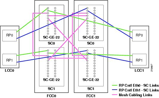
Connections for a Two-FCC System
The figure below shows the cabling scheme for a two-FCC system. The below table lists the cabling connections that must be completed between the RPs and the 22-port SCGE cards and Table 2 lists the mesh cabling connections in a two-FCC system.
|
From Chassis |
From RP Port |
FCC |
To 22-Port SCGE Card Number |
To 22-Port SCGE Card Port Number |
|
LCC0 |
RP0, Cntl Eth 0 |
FCC0 |
SC0 |
GE0 |
|
RP0, Cntl Eth 1 |
FCC1 |
SC0 |
GE0 |
|
|
RP1, Cntl Eth 0 |
FCC0 |
SC1 |
GE0 |
|
|
RP1, Cntl Eth 1 |
FCC1 |
SC1 |
GE0 |
|
|
LCC1 |
RP0, Cntl Eth 0 |
FCC0 |
SC0 |
GE1 |
|
RP0, Cntl Eth 1 |
FCC1 |
SC0 |
GE1 |
|
|
RP1, Cntl Eth 0 |
FCC0 |
SC1 |
GE1 |
|
|
RP1, Cntl Eth 1 |
FCC1 |
SC1 |
GE1 |
|
|
LCC2 |
RP0, Cntl Eth 0 |
FCC0 |
SC0 |
GE2 |
|
RP0, Cntl Eth 1 |
FCC1 |
SC0 |
GE2 |
|
|
RP1, Cntl Eth 0 |
FCC0 |
SC1 |
GE2 |
|
|
RP1, Cntl Eth 1 |
FCC1 |
SC1 |
GE2 |
|
|
LCC3 |
RP0, Cntl Eth 0 |
FCC0 |
SC0 |
GE3 |
|
RP0, Cntl Eth 1 |
FCC1 |
SC0 |
GE3 |
|
|
RP1, Cntl Eth 0 |
FCC0 |
SC1 |
GE3 |
|
|
RP1, Cntl Eth 1 |
FCC1 |
SC1 |
GE3 |
|
|
LCC4 |
RP0, Cntl Eth 0 |
FCC0 |
SC0 |
GE4 |
|
RP0, Cntl Eth 1 |
FCC1 |
SC0 |
GE4 |
|
|
RP1, Cntl Eth 0 |
FCC0 |
SC1 |
GE4 |
|
|
RP1, Cntl Eth 1 |
FCC1 |
SC1 |
GE4 |
|
|
LCC5 |
RP0, Cntl Eth 0 |
FCC0 |
SC0 |
GE5 |
|
RP0, Cntl Eth 1 |
FCC1 |
SC0 |
GE5 |
|
|
RP1, Cntl Eth 0 |
FCC0 |
SC1 |
GE5 |
|
|
RP1, Cntl Eth 1 |
FCC1 |
SC1 |
GE5 |
|
|
LCC6 |
RP0, Cntl Eth 0 |
FCC0 |
SC0 |
GE6 |
|
RP0, Cntl Eth 1 |
FCC1 |
SC0 |
GE6 |
|
|
RP1, Cntl Eth 0 |
FCC0 |
SC1 |
GE6 |
|
|
RP1, Cntl Eth 1 |
FCC1 |
SC1 |
GE6 |
|
|
LCC7 |
RP0, Cntl Eth 0 |
FCC0 |
SC0 |
GE7 |
|
RP0, Cntl Eth 1 |
FCC1 |
SC0 |
GE7 |
|
|
RP1, Cntl Eth 0 |
FCC0 |
SC1 |
GE7 |
|
|
RP1, Cntl Eth 1 |
FCC1 |
SC1 |
GE7 |
|
Originating Chassis |
22-Port SCGE Card Number |
22-Port SCGE Card Port Number |
Destination Chassis |
22-Port SCGE Card Number |
22-Port SCGE Card Port Number |
|
FCC0 |
SC0 |
GE19 |
FCC0 |
SC1 |
GE19 |
|
FCC1 |
SC0 |
GE19 |
FCC1 |
SC1 |
GE19 |
|
FCC0 |
SC0 |
GE20 |
FCC1 |
SC0 |
GE20 |
|
FCC0 |
SC1 |
GE20 |
FCC1 |
SC1 |
GE20 |
|
FCC0 |
SC0 |
GE21 |
FCC1 |
SC1 |
GE21 |
|
FCC0 |
SC1 |
GE21 |
FCC1 |
SC0 |
GE21 |
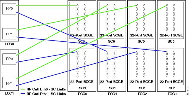
Connections for a Four-FCC System
The figure below shows the cabling scheme for a four-FCC system, but unlike Table 1 and Table 2, does not show the mesh cabling connections in a four-FCC system. Refer to Mesh Cabling (Four-FCC System), cabling connections in a four-FCC system. The table below lists the cabling connections that must be completed between the RPs and the 22-port SCGE cards. Table 1 lists the mesh cabling connections in a four-FCC system.
|
From Chassis |
From RP Port |
FCC |
To 22-Port SCGE Card Number |
To 22-Port SCGE Card Port Number |
|
LCC0 |
RP0, Cntl Eth 0 |
FCC0 |
SC0 |
GE0 |
|
RP0, Cntl Eth 1 |
FCC1 |
SC1 |
GE0 |
|
|
RP1, Cntl Eth 0 |
FCC2 |
SC0 |
GE0 |
|
|
RP1, Cntl Eth 1 |
FCC3 |
SC1 |
GE0 |
|
|
LCC1 |
RP0, Cntl Eth 0 |
FCC1 |
SC0 |
GE0 |
|
RP0, Cntl Eth 1 |
FCC0 |
SC1 |
GE0 |
|
|
RP1, Cntl Eth 0 |
FCC3 |
SC0 |
GE0 |
|
|
RP1, Cntl Eth 1 |
FCC2 |
SC1 |
GE0 |
|
|
LCC2 |
RP0, Cntl Eth 0 |
FCC0 |
SC0 |
GE1 |
|
RP0, Cntl Eth 1 |
FCC1 |
SC1 |
GE1 |
|
|
RP1, Cntl Eth 0 |
FCC2 |
SC0 |
GE1 |
|
|
RP1, Cntl Eth 1 |
FCC3 |
SC1 |
GE1 |
|
|
LCC3 |
RP0, Cntl Eth 0 |
FCC1 |
SC0 |
GE1 |
|
RP0, Cntl Eth 1 |
FCC0 |
SC1 |
GE1 |
|
|
RP1, Cntl Eth 0 |
FCC3 |
SC0 |
GE1 |
|
|
RP1, Cntl Eth 1 |
FCC2 |
SC1 |
GE1 |
|
|
LCC4 |
RP0, Cntl Eth 0 |
FCC0 |
SC0 |
GE2 |
|
RP0, Cntl Eth 1 |
FCC1 |
SC1 |
GE2 |
|
|
RP1, Cntl Eth 0 |
FCC2 |
SC0 |
GE2 |
|
|
RP1, Cntl Eth 1 |
FCC3 |
SC1 |
GE2 |
|
|
LCC5 |
RP0, Cntl Eth 0 |
FCC1 |
SC0 |
GE2 |
|
RP0, Cntl Eth 1 |
FCC0 |
SC1 |
GE2 |
|
|
RP1, Cntl Eth 0 |
FCC3 |
SC0 |
GE2 |
|
|
RP1, Cntl Eth 1 |
FCC2 |
SC1 |
GE2 |
|
|
LCC6 |
RP0, Cntl Eth 0 |
FCC0 |
SC0 |
GE3 |
|
RP0, Cntl Eth 1 |
FCC1 |
SC1 |
GE3 |
|
|
RP1, Cntl Eth 0 |
FCC2 |
SC0 |
GE3 |
|
|
RP1, Cntl Eth 1 |
FCC3 |
SC1 |
GE3 |
|
|
LCC7 |
RP0, Cntl Eth 0 |
FCC1 |
SC0 |
GE3 |
|
RP0, Cntl Eth 1 |
FCC0 |
SC1 |
GE3 |
|
|
RP1, Cntl Eth 0 |
FCC3 |
SC0 |
GE3 |
|
|
RP1, Cntl Eth 1 |
FCC2 |
SC1 |
GE3 |
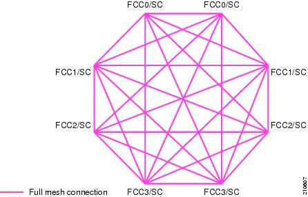
Mesh Cabling (Four-FCC System)
To complete the cabling of a four-FCC system, all of the 22-port SCGE cards in the FCCs must be connected to each other in a full mesh configuration. This provides a great amount of redundancy, so in the event that one of the nodes fails, network traffic is directed to any of the other nodes. The figure below shows a graphical view of the full mesh configuration.
|
Originating Chassis |
22-Port SCGE Card Number |
22-Port SCGE Card Port Number |
Destination Chassis |
22-Port SCGE Card Number |
22-Port SCGE Card Port Number |
|
FCC0 |
SC0 |
GE21 |
FCC0 |
SC1 |
GE21 |
|
SC0 |
GE15 |
FCC1 |
SC0 |
GE15 |
|
|
SC0 |
GE16 |
FCC1 |
SC1 |
GE15 |
|
|
SC0 |
GE17 |
FCC2 |
SC0 |
GE15 |
|
|
SC0 |
GE18 |
FCC2 |
SC1 |
GE15 |
|
|
SC0 |
GE19 |
FCC3 |
SC0 |
GE15 |
|
|
SC0 |
GE20 |
FCC3 |
SC1 |
GE15 |
|
|
FCC0 |
SC1 |
GE15 |
FCC1 |
SC0 |
GE16 |
|
SC1 |
GE16 |
FCC1 |
SC1 |
GE16 |
|
|
SC1 |
GE17 |
FCC2 |
SC0 |
GE16 |
|
|
SC1 |
GE18 |
FCC2 |
SC1 |
GE16 |
|
|
SC1 |
GE19 |
FCC3 |
SC0 |
GE16 |
|
|
SC1 |
GE20 |
FCC3 |
SC1 |
GE16 |
|
|
FCC1 |
SC0 |
GE21 |
FCC1 |
SC1 |
GE21 |
|
SC0 |
GE17 |
FCC2 |
SC0 |
GE17 |
|
|
SC0 |
GE18 |
FCC2 |
SC1 |
GE17 |
|
|
SC0 |
GE19 |
FCC3 |
SC0 |
GE17 |
|
|
SC0 |
GE20 |
FCC3 |
SC1 |
GE17 |
|
|
FCC1 |
SC1 |
GE17 |
FCC2 |
SC0 |
GE18 |
|
SC1 |
GE18 |
FCC2 |
SC1 |
GE18 |
|
|
SC1 |
GE19 |
FCC3 |
SC0 |
GE18 |
|
|
SC1 |
GE20 |
FCC3 |
SC1 |
GE18 |
|
|
FCC2 |
SC0 |
GE21 |
FCC2 |
SC1 |
GE21 |
|
SC0 |
GE19 |
FCC3 |
SC0 |
GE19 |
|
|
SC0 |
GE20 |
FCC3 |
SC1 |
GE19 |
|
|
FCC2 |
SC1 |
GE19 |
FCC3 |
SC0 |
GE20 |
|
SC1 |
GE20 |
FCC3 |
SC1 |
GE20 |
|
|
FCC3 |
SC0 |
GE21 |
FCC3 |
SC1 |
GE21 |
What to Do Next
After you cable the control network, configure the 22-port SCGE cards, as described in Cisco IOS XR Getting Started Guide . The control network must be brought up to enable communications between the racks and to support software downloads from the DSC rack to the other racks.
The final step in cabling the multishelf system is to cable the system fabric, as described in Cabling the Fabric chapter.
 Feedback