Cisco CRS Carrier Routing System Multishelf System Interconnection and Cabling Guide
Bias-Free Language
The documentation set for this product strives to use bias-free language. For the purposes of this documentation set, bias-free is defined as language that does not imply discrimination based on age, disability, gender, racial identity, ethnic identity, sexual orientation, socioeconomic status, and intersectionality. Exceptions may be present in the documentation due to language that is hardcoded in the user interfaces of the product software, language used based on RFP documentation, or language that is used by a referenced third-party product. Learn more about how Cisco is using Inclusive Language.
- Updated:
- November 6, 2016
Chapter: Introduction to Multishelf System Cabling
Introduction to
Multishelf System Cabling
Introduction to Multishelf System Cabling
This chapter provides an overview of the Cisco CRS Carrier Routing System Multishelf System and describes what is required to interconnect system components. The Cisco CRS Carrier Routing System Multishelf System is also called the Cisco CRS Multishelf system or multishelf system .
The multishelf system is a highly scalable routing platform designed for service providers to build next generation multi-service networks that provide video, data and voice services. The multishelf system consists of two major components: 16-slot line card chassis (commonly referred to as LCC) and fabric card chassis (commonly referred to as FCC). The current Cisco IOS XR software release supports up to eight LCCs and one, two, or four FCCs.
 Note | This cabling guide is for a new multishelf system installation. If you are upgrading a Cisco CRS 16-Slot Line Card Chassis to become part of a Cisco CRS Multishelf System, see the Cisco CRS Carrier Routing System Multishelf System Upgrade and Conversion Guide. Also see the Cisco CRS Carrier Routing System Multishelf System Upgrade and Conversion Guide if you are converting a multishelf system from a Cisco Catalyst-based system to a 22-port shelf controller Gigabit Ethernet (22-port SCGE) system. |
The chapter covers the following topics:
- Multishelf System Overview
- Cabling Overview
- General Cabling Prerequisites
- Cable Routing Considerations
- General Cabling Procedures
- Safety Guidelines
Multishelf System Overview
Multishelf system configurations are available with one, two, or four fabric card chassis (FCCs). The single-FCC multishelf system requires a smaller investment, while the two- or four-FCC systems provide additional fault tolerance because the failure of a single FCC does not shut down the system.
These systems are introduced in the following sections:
 Tip | For a complete introduction to multishelf systems, see Cisco CRS Carrier Routing System Multishelf System Description . |
Single-FCC Multishelf System
The Cisco CRS Carrier Routing System is the first carrier routing system in the industry to offer continuous system operation, unprecedented service flexibility, and system longevity. The system is powered by Cisco IOS XR software, a unique self-healing and self-defending operating system designed for continual operation while scaling system capacity from 4.88 Terabits per second (Tbps) for each line card chassis (LCC) up to 322 terabits per second (Tbps) for a fully-loaded multishelf system (MSS). The multishelf system design supports from 2 to 8 LCCs and from 1 to 4 FCCs, for a total switching capacity of up to 322 Tbps.
Note | Refer to the appropriate Cisco IOS XR software release notes online to confirm the multishelf system capacity supported by the Cisco IOS XR software release you have loaded. Currently the upper range of multishelf system capacity supported by Cisco IOS XR software is eight LCCs and four FCCs. |
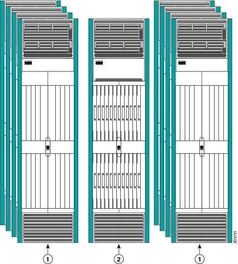
The figure below shows the single-FCC multishelf system, which contains the following major components:
Note | The single-FCC multishelf system also supports up to two 22-port shelf controller Gigabit Ethernet (22-port SCGE) cards per fabric card chassis. |
|
1 |
Cisco CRS 16-Slot Line Card Chassis ( eight shown) |
2 |
Cisco CRS-Fabric Card Chassis (one shown) |
Two-FCC Multishelf System
The figure below shows the two-FCC multishelf system, which contains the following major components:
|
1 |
Cisco CRS 16-Slot Line Card Chassis ( eight shown) |
2 |
Cisco CRS Fabric Card Chassis ( two shown) |
Four-FCC Multishelf System
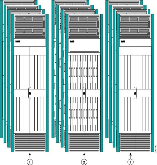
The figure below shows the four-FCC multishelf system, which contains the following major components:
|
1 |
Cisco CRS 16-Slot Line Card Chassis ( eight shown) |
2 |
Cisco CRS Fabric Card Chassis ( four shown) |
Cabling Overview
Multishelf system cabling can be divided into the following groups, and a multishelf system should be cabled in this approximate order:
- System Management, Alarm, and Network Clock Cabling
- Control Network Cabling Using 22-Port SCGE Cards
- Fabric Cabling
- PLIM Port Cabling
System Management, Alarm, and Network Clock Cabling
The Cabling for System Management, Alarms, and Network Clocking chapter describes the cabling for system management connections, the optional network clock feature, and the optional external alarm feature. At least one form of system management connection must be cabled before system configuration can start.
Control Network Cabling Using 22-Port SCGE Cards
The chapter Cabling the Control Network Using 22-Port Shelf Controller Gigabit Ethernet Cards describes the cabling for the control network, which links all racks together and enables the designated shelf controller (DSC) rack to control the other racks in the system. The DSC also uses the control network to download software to the other racks in the system and receive messages on rack status. The control network must be cabled before the system can become operational.
Fabric Cabling
The chapter Cabling the Fabric describes the cabling between the fabric components in the LCCs and the fabric components in the FCCs. The fabric provides the data connection for router traffic between all the modular services card (MSC) ports in the LCCs. The fabric cabling must be completed to enable data communications through the multishelf system.There are two types of fabric cable, Trimese and Riser.
PLIM Port Cabling
All router data traffic enters the multishelf system through lines connected to the physical layer interface modules (PLIMs). For information about PLIM cards and connectors, see the PLIM notes and installation guides on http://cisco.com
General Cabling Prerequisites
The prerequisites for installing a multishelf system include having adequate floor space to cable the system, an environment that meets specifications, the minimum system components needed to create a multishelf system, the tools required to perform the installation, and the proper cables needed to interconnect the chassis to each other, the 22-port SCGE cards, and their power sources. These prerequisites are explained in the following sections:
Space and Environmental Considerations
Space, power, and environmental specifications are cited in the following online guides:
- Cisco CRS Carrier Routing System Multishelf System Site Planning Guide
- Cisco CRS Carrier Routing System 16-Slot Line Card Chassis Site Planning Guide
Tools and Supplies Required
The following tools and supplies are required to cable the multishelf system:
- ESD (ElectroStatic Discharge) wrist strap (for inserting an SFP module)
- 2.5-mm Allen wrench (to screw or unscrew the hex screws on the unistrut)
- Torx T6 wrench (to screw or unscrew the bolt on the fabric cable connector to the OIM or S13 fabric card)
- Medium (number 2) Phillips screwdriver
- Medium flat-blade screwdriver (1/4 inch [60 to 70 mm]). This screwdriver is optional; it’s used for opening the bale latches on small form-factor pluggable [SFP] or Gigabit Interface Converter [GBIC] transceivers.
- Turn collars (to provide support and strain relief for fabric cable connections). The turn collars are supplied with the cable.
- Supply of Velcro tie wraps (to bundle cables)
- Ladder
Cables Required
The cables listed in the below table are required for each LCC in a multishelf system installation.
|
Cable Product ID |
Description |
Purpose |
||
|---|---|---|---|---|
|
Trimese: LCC/M-FC-FBR-xx = (where xx is the length in meters) Riser: LCC/M-FC-FBR-xx R= (where xx is the length in meters) |
Line Card Chassis/Multishelf - Fabric Chassis - Fiber |
To interconnect fabric cards between the LCCs and one or more FCCs.
|
||
|
72-1258-01 |
Gigabit Ethernet cables (green) |
To connect the route processor (RP) cards and shelf controller Gigabit Ethernet (SCGE) cards To connect console cables to the router |
||
|
— |
22-port SCGE card LC to LC Ethernet cable (single mode) |
To connect the DSC RP cards RP0 and RP1 MGMT ETH ports to the 22-port SCGE cards.1 |
For more information on the range of lengths available for the Cisco CRS fabric cables, refer to Cisco Systems Fabric Cables in Cabling the Fabric chapter. Table 1the product ID numbers for Cisco CRS fabric cables. Evaluate your installation for the appropriate length of fabric cable needed before ordering.
Cable Routing Considerations
The elements of the multishelf system that need to be cabled together include:
- Two 22-port SCGE cards per fabric card chassis.
- One, two, or four fabric card chassis
- Two or more line card chassis
Whether the cables will be run overhead or under the floor, consider the airflow and cable characteristics of the combined cable sets to ensure that your cable management structures match or exceed the total capacity of cables for the multishelf system installation.
The following sections provide some cable routing guidelines:
Tip | See the Cisco CRS Carrier Routing System Multishelf System Site Planning Guide for information on planning component locations and cable runs. |
Raised Floor Installations
To plan cable routing in an installation with a raised floor, consider all the characteristics of each cable required for the installation. Allow slack for cabling so that cables can be pooled under the floor for future expansion without exceeding bend radius or cable length limitations. Only use Riser cables in an installation with a raised floor. Riser cables are not rated for installation in air plenum passages, nor are they designed for use in LSZH (low smoke zero halogen) applications.
Cable Characteristics
To plan your cable runs, consider the characteristics of each cable, such as the cable length limitations, combined diameter of bundled cables (such as power cables), weight of the cable groups, and bend radius of the cable or cables. Couple these considerations with the cable infrastructure available (or needed) at your facility. The infrastructure could include structures like the overhead cabling monorail or J-hook system, sleeve and riser diameters, and distances between floors or elements of the multishelf system.
Analyze the cabling infrastructures, risers, and racking available in your facility to determine if the capacity of the cabling management systems at your facility will accommodate the required capacities of the multishelf system cabling.
Note | Trimese fabric cables carry a dual flame rating: general purpose and LSZH (low smoke zero halogen). These cables are designed to connect between an LCC and FCC in the free air of the room. Fabric cables must be routed within a room. Fabric cables are not rated for installation above ceilings, below floors, or through walls. |
Note | Riser fabric cables (LCC-M-C-FBR-xxR) meet the OFNR riser cable flame rating. These cables are designed to connect between an LCC and an FCC, either in the free air within a room, or, through a riser access between building floors. Riser cables are not rated for installation in air plenum passages, nor are they designed for use in LSZH (low smoke zero halogen) applications. |
Cable Length
The limit of the cables is 100 meters (328 feet). Consider this distance when planning the physical locations of the LCCs and FCCs. For more information on the range of lengths available for the Cisco CRS fabric cables, refer to “Cisco Systems Fabric Cables” in the cabling the Fabirc chapter . The Table 1 lists the product ID numbers for Cisco CRS fabric cables. Evaluate your installation for the appropriate length of fabric cable needed before ordering.
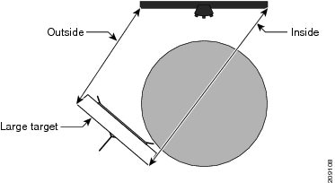
Cable Bend Radius
Exceeding the bend radius allowed for a cable can break the glass in the cable or cause attenuation or loss of signal. Do not bend a cable more than the allowable bend radius.
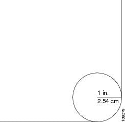
The figure below shows an example of how a bend radius is measured for Trimese cables. In this figure, the cable has a 1-inch (2.54-cm) radius. If the cable is specified to wrap around the arc formed by the circle with the 1-inch radius, the cable is said to have a 1-inch bend radius .
At any time, the bend radius should not be less than 1.25" and less than 2" bend radius for Trimese cables and should not be less than 2” bend radius for Riser cables or should not exceed the bend established by the strain relief collars.
General Cabling Procedures
Observe these procedures as you attach every cable:
- Before you start, determine whether you will route the interconnection cables upward or downward from the fabric card. The direction determines whether you will install the fabric cable turn collar (see ) pointing up or down.
- For horizontal cable management, the rear of the line card chassis has a single horizontal cable manager located between the two shelves. The rear of the fabric card chassis has a horizontal cable manager above the top shelf and above and below the bottom shelf. Strap cable bundles to these brackets.
Handle all cables carefully. Fiber-optic cables require special care as follows:
- Do not allow a fiber-optic cable to bend in a radius smaller than the allowable bend radius specified for that cable type.
- Fiber-optic cables are glass. Do not step on fiber-optic cables or handle them roughly. Do not twist or stretch the cables.
- To keep optical connections clean, do not remove the cable dust cover until immediately before you install the cable. See Cisco CRS Carrier Routing System Optical Cleaning Guide for details.
- After you install a cable, immediately reserve each dust cover for storage by office personnel in a dust-free storage area. After all of the cables have been installed ensure that all the reserved dust covers are stored by office personnel in a dust free area for future use.
- Install clean dust covers on every unused connection.
- Consider labeling the chassis interconnection cables or creating a diagram of the cabling to ensure that the cables are connected correctly during system installation.
- Consider labeling the chassis. Consider whether each chassis need to be physically positioned in sequence. Label each cable with the location of each termination as you install each cable. Refer to the Multimodule Horizontal Cabling Planschapter for examples of multimodule cabling plans.
Safety Guidelines
The following sections describe safety guidelines:
General Safety Guidelines
Before you perform any procedure in this document, review the safety guidelines in this section to avoid injuring yourself or damaging the equipment.
The following guidelines are for your safety and to protect equipment. The guidelines do not include all hazards. Be alert.
Note | Review the Document Conventions section and the Understanding Warning Statement Numbers sections. In addition, review the safety warnings listed in Regulatory Compliance and Safety Information for the Cisco CRS Carrier Routing System before installing, configuring, or troubleshooting any installed card. That booklet shipped with your system. |
- Never attempt to lift an object that might be too heavy for you to lift by yourself.
- Keep the work area clear and dust free during and after installation. Do not allow dirt or debris to enter into any laser-based components.
- Keep tools and router components away from walk areas.
- Do not wear loose clothing, jewelry, or other items that could get caught in the router while working with cards, modules, and their associated components.
- Cisco equipment operates safely when used in accordance with its specifications and product-usage instructions.
- Do not work alone if potentially hazardous conditions exist.
- The installation must follow national and local electrical codes: in the United States, National Fire Protection Association (NFPA) 70, United States National Electrical Code; in Canada, Canadian Electrical Code, part I, CSA C22.1; in other countries, International Electrotechnical Commission (IEC) 60364, part 1 through part 7.
 Feedback