Cisco CRS Carrier Routing System Multishelf System Interconnection and Cabling Guide
Bias-Free Language
The documentation set for this product strives to use bias-free language. For the purposes of this documentation set, bias-free is defined as language that does not imply discrimination based on age, disability, gender, racial identity, ethnic identity, sexual orientation, socioeconomic status, and intersectionality. Exceptions may be present in the documentation due to language that is hardcoded in the user interfaces of the product software, language used based on RFP documentation, or language that is used by a referenced third-party product. Learn more about how Cisco is using Inclusive Language.
- Updated:
- November 6, 2016
Chapter: Cabling the Fabric
Cabling the
Fabric
Cabling the Fabric
The cables used to interconnect the multishelf system chassis are optical array cables called fabric cables. This chapter describes how to physically cable the fabric planes between each line card chassis (LCC) and fabric card chassis (FCC) in a multishelf system and card placement for high availability. This chapter is organized into the following sections:
 Note | This procedure is for a first-time installation of the multishelf system. If you are upgrading a Cisco CRS 16-Slot Line Card Chassis that is carrying live traffic, see Cisco CRS Carrier Routing System Multishelf System Upgrade and Conversion Guide for details. |
- About Fabric Cabling
- Planning Fabric Cabling
- Cabling the Fabric
- General Fabric Cabling Procedures
- What to Do Next
About Fabric Cabling
The multishelf fabric cabling requires 24 fiber fabric cables per LCC. This cabling enables interchassis communication, which is accomplished using fiber-optic bundles. This section describes the following topics:
About Fabric Planes in the Multishelf System
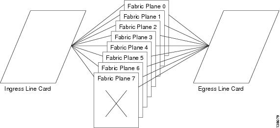
The multishelf system has eight fabric planes that support data traffic between the lines connected to the LCCs. The figure below shows a simplified view of the relationship between the line cards and the fabric.
Each fabric plane is divided into three components or stages, which are numbered S1, S2, and S3. Data arrives at the S1 stage in an LCC, passes over the fabric cables to the S2 stage in an FCC, and then passes over the fabric cables again to the S3 stage in the destination LCC. The figure below shows a simplified view of the relationship between the line cards and the fabric. Refer to Figure 1 and Figure 2 for physical vertical and horizontal cabling examples.
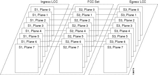
In each LCC, eight S13 fabric cards provide stages S1 and S3 for each of the eight fabric planes. All ingress traffic enters through the S1 component of the ingress S13 card, travels over the fabric cables and S2 fabric component, and exits through the S3 component on an S13 fabric card. Data traffic can enter through the S1 component of one card, pass through the S2 component, and then exit the S3 component of the same card.
The S2 cards are distributed between one, two, or four FCCs. The S2 cards for all fabric planes can be installed in a single FCC, but distributing the planes between FCCs prevents a failure in one FCC from disrupting traffic in all eight planes.
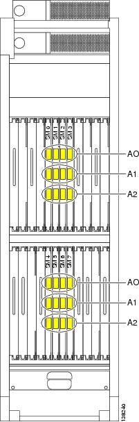
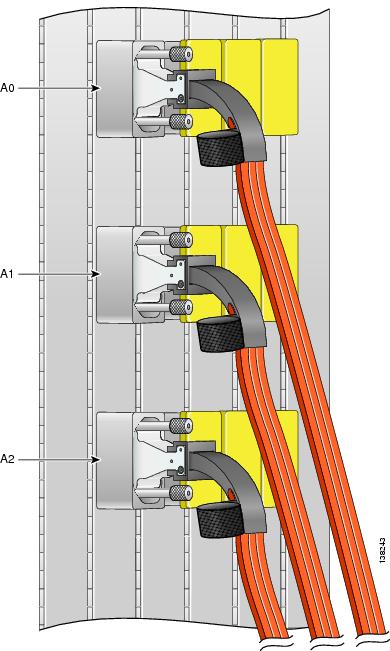
Figure 4 the location of the S13 fabric cards in the LCC and how the connectors are labeled on those cards. The fabric planes are numbered 0 through 7 and are installed in slot numbers SM 0 through SM 7, respectively. Each fabric card has three connectors, which are labeled A0, A1, and A2. Each fabric cable connects to all three S13 card connectors and to one or more S2 cards in an FCC.
The figure below shows eight S2 cards installed in an FCC and how the connectors are labeled on those cards. Unlike the fabric planes in an LCC, the FCC slots are not preconfigured for specific plane numbers. The plane number served by a slot is defined during system configuration. This approach provides the flexibility to distribute the fabric planes between FCCs and distribute the planes in different power zones within an FCC.

|
1 |
OIM in slot FM 0 |
5 |
OIM in slot FM 12 |
|
2 |
OIM in slot FM 3 |
6 |
OIM in slot FM 15 |
|
3 |
OIM in slot FM 6 |
7 |
OIM in slot FM 18 |
|
4 |
OIM in slot FM 9 |
8 |
OIM in slot FM 21 |

|
1 |
OIM in slot FM 0 |
9 |
OIM in slot FM 8 |
17 |
OIM in slot FM 16 |
|
2 |
OIM in slot FM 1 |
10 |
OIM in slot FM 9 |
18 |
OIM in slot FM 17 |
|
3 |
OIM in slot FM 2 |
11 |
OIM in slot FM 10 |
19 |
OIM in slot FM 18 |
|
4 |
OIM in slot FM 3 |
12 |
OIM in slot FM 11 |
20 |
OIM in slot FM 19 |
|
5 |
OIM in slot FM 4 |
13 |
OIM in slot FM 12 |
21 |
OIM in slot FM 20 |
|
6 |
OIM in slot FM 5 |
14 |
OIM in slot FM 13 |
22 |
OIM in slot FM 21 |
|
7 |
OIM in slot FM 6 |
15 |
OIM in slot FM 14 |
23 |
OIM in slot FM 22 |
|
8 |
OIM in slot FM 7 |
16 |
OIM in slot FM 15 |
24 |
OIM in slot FM 23 |
Cisco Systems Fabric Cables
The table below lists the product ID numbers for Cisco CRS fabric cables. The cables listed in the below table can be ordered. The interconnection cables listed are shipped as a set of 24 in the meter length specified. Evaluate your installation for the appropriate length of fabric cable needed before ordering. You should try to avoid long runs of coiled cables.
In the table below, the cable name LCC/M-FC-FBR-XX means the following:
- LCC/M is “Line Card Chassis/Multishelf System.”
- FC is Fabric (Card) Chassis.
- FBR is Fiber.
- xx is the length of the cable in meters.
Note | The = symbol at the end of a product ID number indicates that the part is a spare , which means the part can be ordered. |
Note | The R symbol at the end of a product ID number indicates that the part is a riser rated fiber cable. |
|
Fabric Cable Product ID |
Description and Length |
|
LCC/M-FC-FBR-10= |
Cisco CRS Line Card Chassis-Fabric Chassis Fiber 10 meters (32.8 feet) |
|
LCC/M-FC-FBR-15= |
Cisco CRS Line Card Chassis-Fabric Chassis Fiber 15 meters (49.2 feet) |
|
LCC/M-FC-FBR-20= |
Cisco CRS Line Card Chassis-Fabric Chassis Fiber 20 meters (65.6 feet) |
|
LCC/M-FC-FBR-25= |
Cisco CRS Line Card Chassis-Fabric Chassis Fiber 25 meters (82 feet) |
|
LCC/M-FC-FBR-30= |
Cisco CRS Line Card Chassis-Fabric Chassis Fiber 30 meters (98.43) |
|
LCC/M-FC-FBR-40= |
Cisco CRS Line Card Chassis-Fabric Chassis Fiber 40 meters (131.2 feet) |
|
LCC/M-FC-FBR-50= |
Cisco CRS Line Card Chassis-Fabric Chassis Fiber 50 meters (164 feet) |
|
LCC/M-FC-FBR-60= |
Cisco CRS Line Card Chassis-Fabric Chassis Fiber 60 meters (197 feet) |
|
LCC/M-FC-FBR-70= |
Cisco CRS Line Card Chassis-Fabric Chassis Fiber 70 meters (229.7) |
|
LCC/M-FC-FBR-80= |
Cisco CRS Line Card Chassis-Fabric Chassis Fiber 80 meters (262.5 feet) |
|
LCC/M-FC-FBR-90= |
Cisco CRS Line Card Chassis-Fabric Chassis Fiber 90 meters (295.3feet) |
|
LCC/M-FC-FBR-100= |
Cisco CRS Line Card Chassis-Fabric Chassis Fiber 100 meters (328 feet) |
|
LCC/M-FC-FBR-10R= |
Cisco CRS Line Card Chassis-Fabric Chassis Riser 10 meters (32.8 feet) |
|
LCC/M-FC-FBR-15R= |
Cisco CRS Line Card Chassis-Fabric Chassis Riser 15 meters (49.2 feet) |
|
LCC/M-FC-FBR-20R= |
Cisco CRS Line Card Chassis-Fabric Chassis Riser 20 meters (65.6) |
|
LCC/M-FC-FBR-25R= |
Cisco CRS Line Card Chassis-Fabric Chassis Riser 25 meters (82 feet) |
|
LCC/M-FC-FBR-30R= |
Cisco CRS Line Card Chassis-Fabric Chassis Riser 30 meters (98.43 feet) |
|
LCC/M-FC-FBR-40R= |
Cisco CRS Line Card Chassis-Fabric Chassis Riser 40 meters (131.2 feet) |
|
LCC/M-FC-FBR-50R= |
Cisco CRS Line Card Chassis-Fabric Chassis Riser 50 meters (164 feet) |
|
LCC/M-FC-FBR-60R= |
Cisco CRS Line Card Chassis-Fabric Chassis Riser 60 meters (197 feet) |
|
LCC/M-FC-FBR-70R= |
Cisco CRS Line Card Chassis-Fabric Chassis Riser 70 meters (229.7) |
|
LCC/M-FC-FBR-80R= |
Cisco CRS Line Card Chassis-Fabric Chassis Riser 80 meters (262.5 feet) |
|
LCC/M-FC-FBR-90R= |
Cisco CRS Line Card Chassis-Fabric Chassis Riser 90 meters (295.3 feet) |
|
LCC/M-FC-FBR-100R= |
Cisco CRS Line Card Chassis-Fabric Chassis Riser 100 meters (328 feet) |
Planning Fabric Cabling
There are several components to planning the fabric cabling:
Planning S2 Fabric Card Placement and Cable Connections
The following sections describe and illustrate what you need to know to plan the S2 fabric card placement and fabric cable connections:
Rules for Fabric Connectivity
The following rules and characteristics define the requirements for positioning S2 optical interface modules (OIMs) in the multishelf system and connecting them to the S13 cards in the LCCs.
- Each S2 fabric card can support only one plane. For vertical cabling, eight S2 fabric cards are required. For horizontal cabling, 24 S2 fabric cards are required.
- If a multishelf system uses more than one FCC, the S2 fabric cards should be equally distributed among the FCCs.
- The FCC power
distribution system divides the 24 S2 fabric card slots into several power
zones. In certain multiple-failure scenarios, all the cards in one zone could
lose power. For a multishelf system to operate, one odd-numbered plane and one
even-numbered plane must be active. For maximum fault tolerance, S2 fabric
cards should be distributed among power zones so that the loss of one zone does
not disable all odd-numbered or all even-numbered fabric planes. The power
zones are described in the following documents:
- Cisco CRS Carrier Routing System Multishelf System Description
- Cisco CRS Carrier Routing System 16-Slot Line Card Chassis System Description
- At the LCC end of a fabric cable, the plane number is determined by the slot to which the cable is connected. The other end of each fabric cable must connect to an FCC S2 fabric card designated for the same plane number.
- For vertical cabling, when connecting fabric cables for an LCC to an S2 fabric card, the three cable connectors for each plane should connect to the same ports on every S2 card. For example, the connectors for Rack 0 connect to connectors J0 through J2 on the S2 cards for all planes.
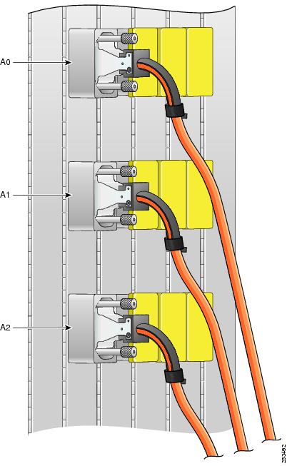
- For horizontal cabling, when connecting fabric cables for an LCC to a series of S2 fabric cards, the three cable connectors for each plane should connect to the same port on each S2 card. For example, the connectors for Rack 0 connect to connector J0 on each S2 card for all planes.
- The connector sequence on the S13 cards must match the connector sequence on the S2 cards. Rack 1 connectors connect to S2 connectors J3 through J5, S13 card connector A0 must connect to S2 connector J3, S13 card connector A1 must connect to S2 connector J4, and S13 card connector A2 must connect to S2 connector J5. [refer to vertical and horizontal cabling plans]
- A single-FCC system stops if the FCC fails, but a two- or four-FCC system can operate as long as one of the FCCs is operational. [not redundant - degraded operation - refer to Cisco CRS Carrier Routing System Multishelf System Description ]
The fabric cabling plans in the chapter Vertical Cabling Plans conform to these rules.
Chassis Cable Routing
After you have determined the placement of the S2 cards and the cable connections, it is time to plan the cable routing.
Plan your cabling runs as suggested in Cisco CRS Carrier Routing System Multishelf System Site Planning Guide. For example, it is convenient when cables are planned, labeled, and hung from overhead cable troughs so that the end of the cable is almost touching the floor. Allow more or less slack as cables are connected. Allow about 0.9 meters (3 feet) of additional cable length for fabric card chassis cable routing.
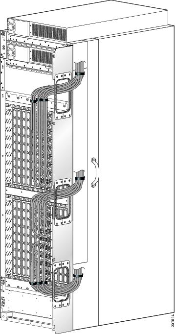
The figure below shows a vertical cabling routing plan for a single-FCC multishelf system. Before you begin cabling, develop a cabling plan for your multishelf system. The example in the figure below routes cables upward to a monorail system and conforms to the following guidelines:
- In the top shelf of the line card chassis, cables are routed downward, toward the side of the chassis, then up and out of the vertical troughs.
- In the bottom shelf of the line card chassis, cables are routed upward, toward the side of the chassis, then up and out of the vertical troughs.
- In the top shelf of the fabric card chassis, cables are routed upward, toward the sides, then up and out the vertical troughs.
- In the bottom shelf of the fabric card chassis, for Vertical Cabling, cables are routed upward, towards the side, then up and out the vertical troughs. Note that for Horizontal Cabling the upper half of the bottom shelf routes upward and the bottom half routes downward.
- When routing riser cables or horizontal cabling, cables need to route outside of the vertical troughs. Figure Cables passing through Cut-Out Slots shows the openings in the side of the vertical troughs where riser cables can pass through. Remove the blank plates and replace with the cable pass through accessory plates.

When preparing to cable the multishelf system, consider the following information:
- For the recommended plan for a single-FCC system, cable planes in this order: 1, 0, 3, 2, 5, 4, 7, 6. This sequence simplifies turn collar installation and cable maintenance because space is tight on the S13 fabric cards (SM slots).
- You can connect the planes in any order. For example, you can start connecting plane 7 to plane 7 first.
- The bend radius of each fabric cable should be no smaller than the arc of the turn collar support.
- Adding new connections later will be easier if the open slots are on the outside of the shelf, so we recommend cabling from the interior out.
- Always put the turn collar on the fabric cable before inserting the cable connector into the OIM connector, as described in the Installing Turning Collars section .
- When you install a fabric cable connector into a OIM card connector, hand-tighten the screws. After you have installed all the fabric cable connectors that go on a OIM card, bundle the cables gently, in sequence, using the Velcro tie wrap on each turn collar. Use additional Velcro tie wraps as needed to route the cables around the support brackets and up the vertical troughs, as shown in the above figure.
- Fabric cables have dust covers, held on by two screws. Fabric card connectors have yellow dust covers that snap on and off. When you take dust covers off, do not put them where they can collect dust. Store unused dust covers in a clean, dust-free area.
- Velcro tie wraps arrive installed in the vertical troughs. Support brackets have slots that allow Velcro tie wraps to attach the cables to the bracket. The figure Closeup of Riser Cables Attached to Ports A0, A1, and A2 on an S13 Card in a Line Card Chassis shows the Velcro straps on an S13 card.
- The figure below shows horizontal cabling routing for a single-FCC two LCC multishelf system. Refer to the Multimodule Horizontal Cabling Plans chapter.

Planning Cable Labels
Label cables as you unpack them. With a felt-tip pen, mark cables as 1, 2, 3 , and so on. Create a consistent labeling scheme. This section suggests a labeling scheme.
Use a label size that works best at your installation. Each label should contain the from and to port location at which either end of the cable is attached. For example, a label could contain the following information:
From:
Bay [row number (for example, a FIC code)]
Rack #
Slot #/Port #
To:
Bay [row number (for example, a FIC code)]
Rack #
Slot #/Port #
where:
- Bay is a row number (for example, a FIC code) or whatever term is appropriate for your site layout.
- Rack # is the rack number for the LCC or FCC.
- Slot #/Port # are slot and port numbers (for example, FM3/A0, which means slot FM3, connector A0). To further explain:
Thus, a label on the Figure 4 might be as shown:
From:
FIC 060184.03 (this means 6th floor, line up 184, bay number 3)
FCC 0
FM14/J5 (this means slot FM 14, port J5)
To:
FIC 060184.05 (this means 6th floor, line up 184, bay number 5)
LCC 5
SM4/A2 (this means slot SM 4, port A2)
Label Schema Example
We suggest that you use a labeling schema, for example, with an Excel spreadsheet. The sample label schema shown in the table below uses the following conventions:
- Each cable should have a minimum of two labels, one label for each end.
- The upper part of the label describes the end at which the label is attached; the lower part describes the other end of the cable.
- Left side or right side refers to the side of the chassis the cable enters the chassis.
- The port number is rack_name /slot_name /port_name .
- The directions in italics are to assist proper placement of the label; they are not part of the label.
- Do not apply the label within 2.5 inches (6.4 cm) from the point at which the cable meets the connector, or the label will be covered by the turn collar. In addition, if the label is farther than 3.5 inches (8.9 cm) from the point at which the cable meets the connector, it might be obscured by the collar of an adjacent cable when installed. Sample label placement is shown in the figure below and Figure 1. A turn collar is shown in Figure 1.
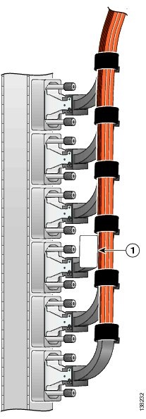
|
1 |
Sample label placement |

|
1 |
Sample label placement |
|
Plane / Label |
Label |
Label |
Label |
Label |
Label |
Plane and LCC or FCC End |
|
Plane number 0 |
||||||
|
Bay 541 |
Bay 541 |
Bay 541 |
Bay 543 |
Bay 543 |
Bay 543 |
Plane 0–LC end |
|
Left side |
Left side |
Left side |
Left side |
Left side |
Left side |
|
|
0/SM0/A0 |
0/SM0/A1 |
0/SM0/A2 |
1/SM0/A0 |
1/SM0/A1 |
1/SM0/A2 |
|
|
Bay 542 |
Bay 542 |
Bay 542 |
Bay 542 |
Bay 542 |
Bay 542 |
|
|
F0/OIM10/J0 |
F0/OIM10/J1 |
F0/OIM10/J2 |
F0/OIM10/J3 |
F0/OIM10/J4 |
F0/OIM10/J5 |
|
|
Flat side to right |
Flat side to right |
Flat side to right |
Flat side to right |
Flat side to right |
Flat side to right |
|
|
Cable turns down |
Cable turns down |
Cable turns down |
Cable turns down |
Cable turns down |
Cable turns down |
|
|
|
|
|
|
|
|
|
|
Bay 542 |
Bay 542 |
Bay 542 |
Bay 542 |
Bay 542 |
Bay 542 |
Plane 0–FC end |
|
Left side |
Left side |
Left side |
Left side |
Left side |
Left side |
|
|
F0/OIM10/J0 |
F0/OIM10/J1 |
F0/OIM10/J2 |
F0/OIM10/J3 |
F0/OIM10/J4 |
F0/OIM10/J5 |
|
|
Bay 541 |
Bay 541 |
Bay 541 |
Bay 543 |
Bay 543 |
Bay 543 |
|
|
0/SM0/A0 |
0/SM0/A1 |
0/SM0/A2 |
1/SM0/A0 |
1/SM0/A1 |
1/SM0/A2 |
|
|
Flat side to left |
Flat side to left |
Flat side to left |
Flat side to left |
Flat side to left |
Flat side to left |
|
|
Cable turns up |
Cable turns up |
Cable turns up |
Cable turns up |
Cable turns up |
Cable turns up |
|
|
Plane number 1 |
||||||
|
Bay 541 |
Bay 541 |
Bay 541 |
Bay 543 |
Bay 543 |
Bay 543 |
Plane 1–LC end |
|
Left side |
Left side |
Left side |
Left side |
Left side |
Left side |
|
|
0/SM1/A0 |
0/SM1/A1 |
0/SM1/A2 |
1/SM1/A0 |
1/SM1/A1 |
1/SM1/A2 |
|
|
Bay 542 |
Bay 542 |
Bay 542 |
Bay 542 |
Bay 542 |
Bay 542 |
|
|
F0/OIM7/J0 |
F0/OIM7/J1 |
F0/OIM7/J2 |
F0/OIM7/J3 |
F0/OIM7/J4 |
F0/OIM7/J5 |
|
|
Flat side to right |
Flat side to right |
Flat side to right |
Flat side to right |
Flat side to right |
Flat side to right |
|
|
Cable turns down |
Cable turns down |
Cable turns down |
Cable turns down |
Cable turns down |
Cable turns down |
|
|
|
|
|
|
|
|
|
|
Bay 542 |
Bay 542 |
Bay 542 |
Bay 542 |
Bay 542 |
Bay 542 |
Plane 1–FC end |
|
Left side |
Left side |
Left side |
Left side |
Left side |
Left side |
|
|
F0/OIM7/J0 |
F0/OIM7/J1 |
F0/OIM7/J2 |
F0/OIM7/J3 |
F0/OIM7/J4 |
F0/OIM7/J5 |
|
|
Bay 541 |
Bay 541 |
Bay 541 |
Bay 543 |
Bay 543 |
Bay 543 |
|
|
0/SM1/A0 |
0/SM1/A1 |
0/SM1/A2 |
1/SM1/A0 |
1/SM1/A1 |
1/SM1/A2 |
|
|
Flat side to left |
Flat side to left |
Flat side to left |
Flat side to left |
Flat side to left |
Flat side to left |
|
|
Cable turns up |
Cable turns up |
Cable turns up |
Cable turns up |
Cable turns up |
Cable turns up |
|
|
Plane number 2 |
||||||
|
Bay 541 |
Bay 541 |
Bay 541 |
Bay 543 |
Bay 543 |
Bay 543 |
Plane 2–LC end |
|
Right side |
Right side |
Right side |
Right side |
Right side |
Right side |
|
|
0/SM2/A0 |
0/SM2/A1 |
0/SM2/A2 |
1/SM2/A0 |
1/SM2/A1 |
1/SM2/A2 |
|
|
Bay 542 |
Bay 542 |
Bay 542 |
Bay 542 |
Bay 542 |
Bay 542 |
|
|
F0/OIM4/J0 |
F0/OIM4/J1 |
F0/OIM4/J2 |
F0/OIM4/J3 |
F0/OIM4/J4 |
F0/OIM4/J5 |
|
|
Flat side to right |
Flat side to right |
Flat side to right |
Flat side to right |
Flat side to right |
Flat side to right |
|
|
Cable turns down |
Cable turns down |
Cable turns down |
Cable turns down |
Cable turns down |
Cable turns down |
|
|
|
|
|
|
|
|
|
|
Bay 542 |
Bay 542 |
Bay 542 |
Bay 542 |
Bay 542 |
Bay 542 |
Plane 2–FC end |
|
Right side |
Right side |
Right side |
Right side |
Right side |
Right side |
|
|
F0/OIM4/J0 |
F0/OIM4/J1 |
F0/OIM4/J2 |
F0/OIM4/J3 |
F0/OIM4/J4 |
F0/OIM4/J5 |
|
|
Bay 541 |
Bay 541 |
Bay 541 |
Bay 543 |
Bay 543 |
Bay 543 |
|
|
0/SM2/A0 |
0/SM2/A1 |
0/SM2/A2 |
1/SM2/A0 |
1/SM2/A1 |
1/SM2/A2 |
|
|
Flat side to left |
Flat side to left |
Flat side to left |
Flat side to left |
Flat side to left |
Flat side to left |
|
|
Cable turns up |
Cable turns up |
Cable turns up |
Cable turns up |
Cable turns up |
Cable turns up |
|
|
Plane number 3 |
||||||
|
Bay 541 |
Bay 541 |
Bay 541 |
Bay 543 |
Bay 543 |
Bay 543 |
Plane 3–LC end |
|
Right side |
Right side |
Right side |
Right side |
Right side |
Right side |
|
|
0/SM3/A0 |
0/SM3/A1 |
0/SM3/A2 |
1/SM3/A0 |
1/SM3/A1 |
1/SM3/A2 |
|
|
Bay 542 |
Bay 542 |
Bay 542 |
Bay 542 |
Bay 542 |
Bay 542 |
|
|
F0/OIM1/J0 |
F0/OIM1/J1 |
F0/OIM1/J2 |
F0/OIM1/J3 |
F0/OIM1/J4 |
F0/OIM1/J5 |
|
|
Flat side to right |
Flat side to right |
Flat side to right |
Flat side to right |
Flat side to right |
Flat side to right |
|
|
Cable turns down |
Cable turns down |
Cable turns down |
Cable turns down |
Cable turns down |
Cable turns down |
|
|
|
|
|
|
|
|
|
|
Bay 542 |
Bay 542 |
Bay 542 |
Bay 542 |
Bay 542 |
Bay 542 |
Plane 3–FC end |
|
Right side |
Right side |
Right side |
Right side |
Right side |
Right side |
|
|
F0/OIM1/J0 |
F0/OIM1/J1 |
F0/OIM1/J2 |
F0/OIM1/J3 |
F0/OIM1/J4 |
F0/OIM1/J5 |
|
|
Bay 541 |
Bay 541 |
Bay 541 |
Bay 543 |
Bay 543 |
Bay 543 |
|
|
0/SM3/A0 |
0/SM3/A1 |
0/SM3/A2 |
1/SM3/A0 |
1/SM3/A1 |
1/SM3/A2 |
|
|
Flat side to left |
Flat side to left |
Flat side to left |
Flat side to left |
Flat side to left |
Flat side to left |
|
|
Cable turns up |
Cable turns up |
Cable turns up |
Cable turns up |
Cable turns up |
Cable turns up |
|
|
Plane number 4 |
||||||
|
Bay 541 |
Bay 541 |
Bay 541 |
Bay 543 |
Bay 543 |
Bay 543 |
Plane 4–LC end |
|
Left side |
Left side |
Left side |
Left side |
Left side |
Left side |
|
|
0/SM4/A0 |
0/SM4/A1 |
0/SM4/A2 |
1/SM4/A0 |
1/SM4/A1 |
1/SM4/A2 |
|
|
Bay 542 |
Bay 542 |
Bay 542 |
Bay 542 |
Bay 542 |
Bay 542 |
|
|
F0/OIM22/J0 |
F0/OIM22/J1 |
F0/OIM22/J2 |
F0/OIM22/J3 |
F0/OIM22/J4 |
F0/OIM22/J5 |
|
|
Flat side to right |
Flat side to right |
Flat side to right |
Flat side to right |
Flat side to right |
Flat side to right |
|
|
Cable turns up |
Cable turns up |
Cable turns up |
Cable turns up |
Cable turns up |
Cable turns up |
|
|
|
|
|
|
|
|
|
|
Bay 542 |
Bay 542 |
Bay 542 |
Bay 542 |
Bay 542 |
Bay 542 |
Plane 4–FC end |
|
Left side |
Left side |
Left side |
Left side |
Left side |
Left side |
|
|
F0/OIM22/J0 |
F0/OIM22/J1 |
F0/OIM22/J2 |
F0/OIM22/J3 |
F0/OIM22/J4 |
F0/OIM22/J5 |
|
|
Bay 541 |
Bay 541 |
Bay 541 |
Bay 543 |
Bay 543 |
Bay 543 |
|
|
0/SM4/A0 |
0/SM4/A1 |
0/SM4/A2 |
1/SM4/A0 |
1/SM4/A1 |
1/SM4/A2 |
|
|
Flat side to left |
Flat side to left |
Flat side to left |
Flat side to left |
Flat side to left |
Flat side to left |
|
|
Cable turns up |
Cable turns up |
Cable turns up |
Cable turns up |
Cable turns up |
Cable turns up |
|
|
Plane number 5 |
||||||
|
Bay 541 |
Bay 541 |
Bay 541 |
Bay 543 |
Bay 543 |
Bay 543 |
Plane 5–LC end |
|
Left side |
Left side |
Left side |
Left side |
Left side |
Left side |
|
|
0/SM5/A0 |
0/SM5/A1 |
0/SM5/A2 |
1/SM5/A0 |
1/SM5/A1 |
1/SM5/A2 |
|
|
Bay 542 |
Bay 542 |
Bay 542 |
Bay 542 |
Bay 542 |
Bay 542 |
|
|
F0/OIM19/J0 |
F0/OIM19/J1 |
F0/OIM19/J2 |
F0/OIM19/J3 |
F0/OIM19/J4 |
F0/OIM19/J5 |
|
|
Flat side to right |
Flat side to right |
Flat side to right |
Flat side to right |
Flat side to right |
Flat side to right |
|
|
Cable turns up |
Cable turns up |
Cable turns up |
Cable turns up |
Cable turns up |
Cable turns up |
|
|
|
|
|
|
|
|
|
|
Bay 542 |
Bay 542 |
Bay 542 |
Bay 542 |
Bay 542 |
Bay 542 |
Plane 5–FC end |
|
Left side |
Left side |
Left side |
Left side |
Left side |
Left side |
|
|
F0/OIM19/J0 |
F0/OIM19/J1 |
F0/OIM19/J2 |
F0/OIM19/J3 |
F0/OIM19/J4 |
F0/OIM19/J5 |
|
|
Bay 541 |
Bay 541 |
Bay 541 |
Bay 543 |
Bay 543 |
Bay 543 |
|
|
0/SM5/A0 |
0/SM5/A1 |
0/SM5/A2 |
1/SM5/A0 |
1/SM5/A1 |
1/SM5/A2 |
|
|
Flat side to left |
Flat side to left |
Flat side to left |
Flat side to left |
Flat side to left |
Flat side to left |
|
|
Cable turns up |
Cable turns up |
Cable turns up |
Cable turns up |
Cable turns up |
Cable turns up |
|
|
Plane number 6 |
||||||
|
Bay 541 |
Bay 541 |
Bay 541 |
Bay 543 |
Bay 543 |
Bay 543 |
Plane 6–LC end |
|
Right side |
Right side |
Right side |
Right side |
Right side |
Right side |
|
|
0/SM6/A0 |
0/SM6/A1 |
0/SM6/A2 |
1/SM6/A0 |
1/SM6/A1 |
1/SM6/A2 |
|
|
Bay 542 |
Bay 542 |
Bay 542 |
Bay 542 |
Bay 542 |
Bay 542 |
|
|
F0/OIM16/J0 |
F0/OIM16/J1 |
F0/OIM16/J2 |
F0/OIM16/J3 |
F0/OIM16/J4 |
F0/OIM16/J5 |
|
|
Flat side to right |
Flat side to right |
Flat side to right |
Flat side to right |
Flat side to right |
Flat side to right |
|
|
Cable turns up |
Cable turns up |
Cable turns up |
Cable turns up |
Cable turns up |
Cable turns up |
|
|
|
|
|
|
|
|
|
|
Bay 542 |
Bay 542 |
Bay 542 |
Bay 542 |
Bay 542 |
Bay 542 |
Plane 6–FC end |
|
Right side |
Right side |
Right side |
Right side |
Right side |
Right side |
|
|
F0/OIM16/J0 |
F0/OIM16/J1 |
F0/OIM16/J2 |
F0/OIM16/J3 |
F0/OIM16/J4 |
F0/OIM16/J5 |
|
|
Bay 541 |
Bay 541 |
Bay 541 |
Bay 543 |
Bay 543 |
Bay 543 |
|
|
0/SM6/A0 |
0/SM6/A1 |
0/SM6/A2 |
1/SM6/A0 |
1/SM6/A1 |
1/SM6/A2 |
|
|
Flat side to left |
Flat side to left |
Flat side to left |
Flat side to left |
Flat side to left |
Flat side to left |
|
|
Cable turns up |
Cable turns up |
Cable turns up |
Cable turns up |
Cable turns up |
Cable turns up |
|
|
Plane number 7 |
||||||
|
Bay 541 |
Bay 541 |
Bay 541 |
Bay 543 |
Bay 543 |
Bay 543 |
Plane 7–LC end |
|
Right side |
Right side |
Right side |
Right side |
Right side |
Right side |
|
|
0/SM7/A0 |
0/SM7/A1 |
0/SM7/A2 |
1/SM7/A0 |
1/SM7/A1 |
1/SM7/A2 |
|
|
Bay 542 |
Bay 542 |
Bay 542 |
Bay 542 |
Bay 542 |
Bay 542 |
|
|
F0/OIM13/J0 |
F0/OIM13/J1 |
F0/OIM13/J2 |
F0/OIM13/J3 |
F0/OIM13/J4 |
F0/OIM13/J5 |
|
|
Flat side to right |
Flat side to right |
Flat side to right |
Flat side to right |
Flat side to right |
Flat side to right |
|
|
Cable turns up |
Cable turns up |
Cable turns up |
Cable turns up |
Cable turns up |
Cable turns up |
|
|
|
|
|
|
|
|
|
|
Bay 542 |
Bay 542 |
Bay 542 |
Bay 542 |
Bay 542 |
Bay 542 |
Plane 7–FC end |
|
Right side |
Right side |
Right side |
Right side |
Right side |
Right side |
|
|
F0/OIM13/J0 |
F0/OIM13/J1 |
F0/OIM13/J2 |
F0/OIM13/J3 |
F0/OIM13/J4 |
F0/OIM13/J5 |
|
|
Bay 541 |
Bay 541 |
Bay 541 |
Bay 543 |
Bay 543 |
Bay 543 |
|
|
0/SM7/A0 |
0/SM7/A1 |
0/SM7/A2 |
1/SM7/A0 |
1/SM7/A1 |
1/SM7/A2 |
|
|
Flat side to left |
Flat side to left |
Flat side to left |
Flat side to left |
Flat side to left |
Flat side to left |
|
|
Cable turns up |
Cable turns up |
Cable turns up |
Cable turns up |
Cable turns up |
Cable turns up |
|
Cabling the Fabric
Precautions
Please observe all precautions listed in the General Safety Guidelines when you perform any procedure in this chapter. The following precautions are additional reminders before you begin cabling the multishelf system.
Because invisible radiation may be emitted from the aperture of the port when no fiber cable is connected, avoid exposure to radiation and do not stare into open apertures. Statement 125
During this procedure, wear grounding wrist straps to avoid ESD damage to the card. Do not directly touch the backplane with your hand or any metal tool, or you could shock yourself. Statement 94
Before working on equipment that is connected to power lines, remove jewelry (including rings, necklaces, and watches). Metal objects will heat up when connected to power and ground and can cause serious burns or weld the metal object to the terminals. Statement 43
If a chassis power is on, assume lasers are turned on.
Never look at the ends of the fiber cables unless you are certain the laser is powered off.
The S2 and S13 cards are Class 1M. Other optical cards are Class 1.
For diverging beams, viewing the laser output with certain optical instruments within a distance of 100 MM. may pose an eye hazard. For collimated beams, viewing the laser output with certain optical instruments designed for use at a distance may pose an eye hazard. Statement 282
Laser radiation. Do not view directly with optical instruments. Class 1M laser product. Statement 283
 Caution | Handle cables carefully, as described in the chapter Introduction to Multishelf System Cabling |
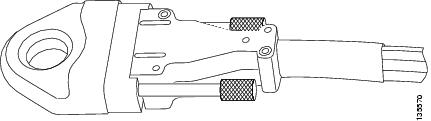
Caution | Cleanliness is critical to proper switch operation. To keep connections clean, do not remove the yellow dust cover from a port until you are ready to attach a cable. Do not remove the silver dust cover from a fabric cable until you are ready to attach the cable to the fabric card connector. Silver dust covers should be screwed on for security. Loosen the screws to remove the dust cover (see the figure below). Store dust covers in a dust-free location. |
Prerequisites
Cable connection procedures assume that all FCCs, LCCs, and their cards are installed in accordance with site planning guidelines and that appropriate interconnection cable lengths are ordered and ready to be connected.
Caution | All ports should have yellow dust covers on them as you begin this procedure, as shown in About Fabric Planes in the Multishelf System. |
How to Connect the Fabric Cables
The fabric cables are shipped separately from the fabric card chassis. These cables are shipped on a reel, similar to as shown in the figure below. This procedure begins with the assumption that the fabric cables have been unpacked and positioned or hung near the chassis to which they will be connected. Packaging for riser rated cables may differ from he figure below.

You will be attaching 24 fabric cables for each LCC. Ensure that each cable is labeled at both ends and then run each cable between the LCC(s) and the FCC. Use of the FCC vertical cable troughs or the side ports is determined by the cabling scheme (vertical or horizontal) and cable type (Trimese or Riser). Refer to Cabling scheme section.
Attach LCC(s)
The steps to take while attaching each cable to the LCC follow:
| Step 1 | Slide the turn collar support on in the direction shown below:Upper shelf - all turn collars go down. Lower shelf - all turn collars go up. |
| Step 2 | Gently position the connector in the correct orientation (fabric card connectors and fabric cable connectors are keyed). |
| Step 3 | Hand-tighten the thumbscrews on the connector. |
| Step 4 | Repeat Steps 1 through 3 to each cable. |
| Step 5 | Fully tighten every connection. |
| Step 6 | Gently drape and group cables behind the fabric card. Use Velcro straps to tie the growing bundles together. |
| Step 7 | Bundle the cables together and velcro them to the horizontal cable manager and the vertical trough. |
Attach FCC
The steps to take while attaching each cable to the FCC follow:
| Step 1 | Slide the turn collar support on in the direction shown below:Vertical Cabling: Upper or lower shelf - all turn collars go up. Horizontal Cabling: Upper shelf - all turn collars go up.Horizontal Cabling: Lower shelf - J0, J1, J2 and J3 turn collars go up. Horizontal Cabling: Lower shelf - J4, J5, J6, J7 and J8 turn collars go down. |
| Step 2 | Gently position the connector in the correct orientation (fabric card connectors and fabric cable connectors are keyed). |
| Step 3 | Hand-tighten the thumbscrews on the connector. |
| Step 4 | Repeat Steps 1 through 3 to each cable. |
| Step 5 | Fully tighten every connection. |
| Step 6 | Gently drape and group cables behind the fabric card. Use Velcro straps to tie the growing bundles together. |
| Step 7 | Bundle the cables together and velcro them to the horizontal cable manager. For vertical cabling with Trimese cables, bundle the cables together and velcro them to the vertical troughs. |
What to Do Next
General Fabric Cabling Procedures
The following are general fabric cabling procedures you might want to use when installing or maintaining the fabric cabling:
- Installing Turn Collars
- Cleaning Cables
- Verifying the Fabric1
- Fabric Chassis Power Zones and Card Placement for High Availability
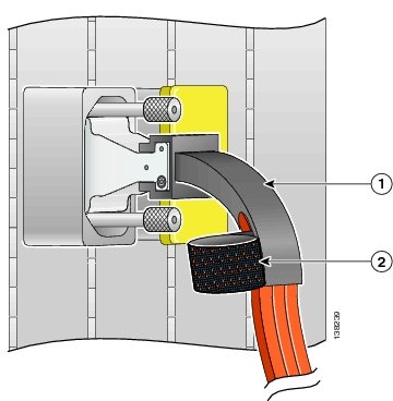
Installing Turn Collars
The turn collar protects the fabric cable bend radius and functions as a strain-relief support. It also has a Velcro strap attached to it to bundle the cables as the cables are installed.
Here are notes to help you install a turn collar:
- The connector is keyed. One side is flat, and the other side has a diagonal cut from the corners.
- Connectors in S13 cards have the flat side on the right; connectors on OIMs have the flat side on the left.
- Turn collars can be slipped onto either side of the connector, depending on whether the cable should turn up or down for proper routing through the chassis.
To install a turn collar:
What to Do Next
1
Turn
collar
2
Velcro
strap (to keep the fabric cable inside the turn collar and bundle fabric
cables)

Cleaning Cables
For information about cleaning fiber-optic cables, see Cisco CRS-1 Optical Cleaning Guide.
Verifying the Fabric1
This section describes, in table form, the processes for executing the commands required to verify the fabric. All commands in this mode will be run from admin mode.
| Step 1 | Execute the
command: show platform. The command will have output similar to below.
Specifically, note that there are 24 SM cards (SM0-23) and all are in IOS XR
RUN state. Also note the 8 LCC SM cards.
Example: Node Type PLIM State Config State ----------------------------------------------------------------------------- 0/RP0/CPU0 RP(Active) N/A IOS XR RUN PWR,NSHUT,MON 0/RP1/CPU0 RP(Standby) N/A IOS XR RUN PWR,NSHUT,MON 0/FC0/SP LCC-FAN-CT(SP) N/A IOS XR RUN PWR,NSHUT,MON 0/FC1/SP LCC-FAN-CT(SP) N/A IOS XR RUN PWR,NSHUT,MON 0/AM0/SP ALARM(SP) N/A IOS XR RUN PWR,NSHUT,MON 0/AM1/SP ALARM(SP) N/A IOS XR RUN PWR,NSHUT,MON 0/SM0/SP FC/M(SP) N/A IOS XR RUN PWR,NSHUT,MON 0/SM1/SP FC/M(SP) N/A IOS XR RUN PWR,NSHUT,MON 0/SM2/SP FC/M(SP) N/A IOS XR RUN PWR,NSHUT,MON 0/SM3/SP FC/M(SP) N/A IOS XR RUN PWR,NSHUT,MON 0/SM4/SP FC/M(SP) N/A IOS XR RUN PWR,NSHUT,MON 0/SM5/SP FC/M(SP) N/A IOS XR RUN PWR,NSHUT,MON 0/SM6/SP FC/M(SP) N/A IOS XR RUN PWR,NSHUT,MON 0/SM7/SP FC/M(SP) N/A IOS XR RUN PWR,NSHUT,MON 1/RP0/CPU0 RP(Active) N/A IOS XR RUN PWR,NSHUT,MON 1/RP1/CPU0 RP(Standby) N/A IOS XR RUN PWR,NSHUT,MON 1/FC0/SP LCC-FAN-CT(SP) N/A IOS XR RUN PWR,NSHUT,MON 1/FC1/SP LCC-FAN-CT(SP) N/A IOS XR RUN PWR,NSHUT,MON 1/AM0/SP ALARM(SP) N/A IOS XR RUN PWR,NSHUT,MON 1/AM1/SP ALARM(SP) N/A IOS XR RUN PWR,NSHUT,MON 1/SM0/SP FC/M(SP) N/A IOS XR RUN PWR,NSHUT,MON 1/SM1/SP FC/M(SP) N/A IOS XR RUN PWR,NSHUT,MON 1/SM2/SP FC/M(SP) N/A IOS XR RUN PWR,NSHUT,MON 1/SM3/SP FC/M(SP) N/A IOS XR RUN PWR,NSHUT,MON 1/SM4/SP FC/M(SP) N/A IOS XR RUN PWR,NSHUT,MON 1/SM5/SP FC/M(SP) N/A IOS XR RUN PWR,NSHUT,MON 1/SM6/SP FC/M(SP) N/A IOS XR RUN PWR,NSHUT,MON 1/SM7/SP FC/M(SP) N/A IOS XR RUN PWR,NSHUT,MON F0/SM0/SP FCC-SFC(SP) FCC-FM-1S IOS XR RUN PWR,NSHUT,MON F0/SM1/SP FCC-SFC(SP) FCC-FM-1S IOS XR RUN PWR,NSHUT,MON F0/SM2/SP FCC-SFC(SP) FCC-FM-1S IOS XR RUN PWR,NSHUT,MON F0/SM3/SP FCC-SFC(SP) FCC-FM-1S IOS XR RUN PWR,NSHUT,MON F0/SM4/SP FCC-SFC(SP) FCC-FM-1S IOS XR RUN PWR,NSHUT,MON F0/SM5/SP FCC-SFC(SP) FCC-FM-1S IOS XR RUN PWR,NSHUT,MON F0/SM6/SP FCC-SFC(SP) FCC-FM-1S IOS XR RUN PWR,NSHUT,MON F0/SM7/SP FCC-SFC(SP) FCC-FM-1S IOS XR RUN PWR,NSHUT,MON F0/SM8/SP FCC-SFC(SP) FCC-FM-1S IOS XR RUN PWR,NSHUT,MON F0/SM9/SP FCC-SFC(SP) FCC-FM-1S IOS XR RUN PWR,NSHUT,MON F0/SM10/SP FCC-SFC(SP) FCC-FM-1S IOS XR RUN PWR,NSHUT,MON F0/SM11/SP FCC-SFC(SP) FCC-FM-1S IOS XR RUN PWR,NSHUT,MON F0/SM12/SP FCC-SFC(SP) FCC-FM-1S IOS XR RUN PWR,NSHUT,MON F0/SM13/SP FCC-SFC(SP) FCC-FM-1S IOS XR RUN PWR,NSHUT,MON F0/SM14/SP FCC-SFC(SP) FCC-FM-1S IOS XR RUN PWR,NSHUT,MON F0/SM15/SP FCC-SFC(SP) FCC-FM-1S IOS XR RUN PWR,NSHUT,MON F0/SM16/SP FCC-SFC(SP) FCC-FM-1S IOS XR RUN PWR,NSHUT,MON F0/SM17/SP FCC-SFC(SP) FCC-FM-1S IOS XR RUN PWR,NSHUT,MON F0/SM18/SP FCC-SFC(SP) FCC-FM-1S IOS XR RUN PWR,NSHUT,MON F0/SM19/SP FCC-SFC(SP) FCC-FM-1S IOS XR RUN PWR,NSHUT,MON F0/SM20/SP FCC-SFC(SP) FCC-FM-1S IOS XR RUN PWR,NSHUT,MON F0/SM21/SP FCC-SFC(SP) FCC-FM-1S IOS XR RUN PWR,NSHUT,MON F0/SM22/SP FCC-SFC(SP) FCC-FM-1S IOS XR RUN PWR,NSHUT,MON F0/SM23/SP FCC-SFC(SP) FCC-FM-1S IOS XR RUN PWR,NSHUT,MON F0/SC0/CPU0 FCC-SC(Active) N/A IOS XR RUN PWR,NSHUT,MON1 F0/SC1/CPU0 FCC-SC(Standby) N/A IOS XR RUN PWR,NSHUT,MON F0/AM0/SP ALARM(SP) N/A IOS XR RUN PWR,NSHUT,MON F0/AM1/SP ALARM(SP) N/A IOS XR RUN PWR,NSHUT,MON F0/LM0/SP FCC-LED(SP) N/A IOS XR RUN PWR,NSHUT,MON F0/LM1/SP FCC-LED(SP) N/A IOS XR RUN PWR,NSHUT,MON |
| Step 2 | Execute the
command: show controllers fabric plane all detail. All planes should be UP/UP
and the amount of downed bundles should be 21 on each plane. If there are more
than 21 downed bundles, it means that at least one of the array cables is loose
or not connected properly.
Example: Flags: P - plane admin down, p - plane oper down C - card admin down, c - card oper down L - link port admin down, l - linkport oper down A - asic admin down, a - asic oper down B - bundle port admin Down, b - bundle port oper down I - bundle admin down, i - bundle oper down N - node admin down, n - node down o - other end of link down d - data down f - failed component downstream m - plane multicast down Plane Admin Oper Down Total Down Id State State Flags Bundles Bundles ------------------------------------------------------ 0 UP UP 27 21 1 UP UP 27 21 2 UP UP 27 21 3 UP UP 27 21 4 UP UP 27 21 5 UP UP 27 21 6 UP UP 27 21 7 UP UP 27 21 |
| Step 3 | Execute the
command: show controllers fabric connectivity all detail. Each one of your line
cards will be represented in the output. Verify that there is connectivity to
all 8 planes. This will be represented by 8 1’s, like below.
Example: Flags: P - plane admin down, p - plane oper down C - card admin down, c - card oper down L - link port admin down, l - linkport oper down A - asic admin down, a - asic oper down B - bundle port admin Down, b - bundle port oper down I - bundle admin down, i - bundle oper down N - node admin down, n - node down o - other end of link down d - data down f - failed component downstream m - plane multicast down Card In Tx Planes Rx Planes Monitored Total Percent R/S/M Use 01234567 01234567 For (s) Uptime (s) Uptime ------------------------------------------------------------------------------- 0/RP0/CPU0 1 11111111 11111111 12702 12702 100.0000 0/RP1/CPU0 1 11111111 11111111 12702 12702 100.0000 1/RP0/CPU0 1 11111111 11111111 50137 50137 100.0000 1/RP1/CPU0 1 11111111 11111111 50137 50137 100.0000 |
| Step 4 | Execute the
command: show controllers fabric bundle all detail | include FM/0. This command
will show you output like below. Verify that each line shows 72 and 0. This
shows that for Line Card Chassis 0, each of the fiber bundles has 72 active
links and 0 downed links. If the output does not look like below, try cleaning
the cable that is showing the problem.
Example: F0/SM0/FM/0 UP 3 72 0 F0/SM0/FM/0 0/SM3/SP/2 F0/SM1/FM/0 UP 3 72 0 F0/SM1/FM/0 0/SM3/SP/1 F0/SM2/FM/0 UP 3 72 0 F0/SM2/FM/0 0/SM3/SP/0 F0/SM3/FM/0 UP 2 72 0 F0/SM3/FM/0 0/SM2/SP/2 F0/SM4/FM/0 UP 2 72 0 F0/SM4/FM/0 0/SM2/SP/1 19-24 F0/SM5/FM/0 UP 2 72 0 F0/SM5/FM/0 0/SM2/SP/0 F0/SM6/FM/0 UP 1 72 0 F0/SM6/FM/0 0/SM1/SP/2 F0/SM7/FM/0 UP 1 72 0 F0/SM7/FM/0 0/SM1/SP/1 F0/SM8/FM/0 UP 1 72 0 F0/SM8/FM/0 0/SM1/SP/0 F0/SM9/FM/0 UP 0 72 0 F0/SM9/FM/0 0/SM0/SP/2 F0/SM10/FM/0 UP 0 72 0 F0/SM10/FM/0 0/SM0/SP/1 F0/SM11/FM/0 UP 0 72 0 F0/SM11/FM/0 0/SM0/SP/0 F0/SM13/FM/0 UP 4 72 0 F0/SM13/FM/0 0/SM4/SP/1 F0/SM14/FM/0 UP 4 72 0 F0/SM14/FM/0 0/SM4/SP/2 F0/SM16/FM/0 UP 5 72 0 F0/SM16/FM/0 0/SM5/SP/1 F0/SM17/FM/0 UP 5 72 0 F0/SM17/FM/0 0/SM5/SP/2 F0/SM19/FM/0 UP 6 72 0 F0/SM19/FM/0 0/SM6/SP/1 F0/SM20/FM/0 UP 6 72 0 F0/SM20/FM/0 0/SM6/SP/2 F0/SM22/FM/0 UP 7 72 0 F0/SM22/FM/0 0/SM7/SP/1 F0/SM23/FM/0 UP 7 72 0 F0/SM23/FM/0 0/SM7/SP/2 |
| Step 5 | Also execute the command: show controllers fabric bundle all detail | include FM/1. Verify the output as above. This will check Line Card Chassis 1. |
| Step 6 | Execute the command: show controllers fabric plane all statistics. Verify that the output looks similar to below. The actual number of packets does not matter, as long as all fabric planes are showing some packets passed and no increasing errors. It is normal to have a few UCEs across the planes and many CEs on Plane 4. |
What to Do Next
When the multishelf system cabling is complete, see Cisco IOS XR Getting Started Guide for directions on bringing up the system.
Fabric Chassis Power Zones and Card Placement for High Availability
This section describes the power zones in the FCC and provides information about how to install cards in the chassis so that a double-fault power failure does not disrupt service when a fixed configuration power system is installed. A double-fault power failure cannot occur in the modular configuration power system because all power modules power all chassis power zones.
Note | The concept of power zones only applies to the older power supplies and power shelf. With the newer power supplies and power shelf, power distribution changes to a bus system so concept of power zones no longer applies. |
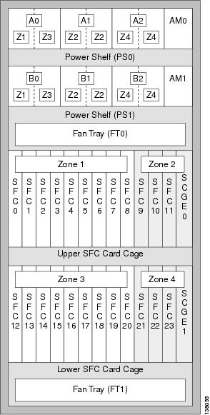
The figure below shows the power zones on the front (SFC) side of a fixed configuration AC-powered FCC.
The figure below shows the power zones on the rear (OIM) side of a fixed configuration AC-powered FCC.

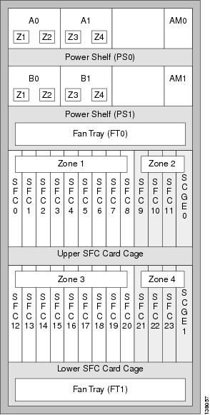
The figure below shows the power zones on the front (SFC) side of a fixed configuration DC-powered FCC.
The figure below shows the power zones on the rear (OIM) side of a fixed configuration DC-powered FCC.
In a configuration with two FCCs, each switch fabric card implements a single plane of the eight-plane switch fabric. If a chassis slot loses power, that plane of the switch fabric stops operating. Although the Cisco CRS router can continue to operate with fewer than eight planes of the switch fabric, you can reduce the amount of performance degradation that occurs by carefully planning how to install fabric cards in the FCC.
For example, in a fixed configuration AC-powered system, if both power modules A0 and B0 fail, chassis slots 0 through 8 and 12 through 20 would lose power, and all switch fabric cards installed in those slots stop operating. If you had installed all of the fabric cards in slots 0 to 8 or in slots 12 to 20, the loss of A0 and B0 results in a complete system failure because none of the switch fabric planes would be active and operational.
We recommend that you distribute the switch fabric planes across chassis power zones to avoid a single point of failure that can result in the loss of switch fabric connectivity during a double-fault power failure. In two- and four-FCC multishelf systems, we recommend that you distribute the fabric planes across all FCCs.
Note | At least two planes of the switch fabric (an even plane and an odd plane) must be active at all times for the Cisco CRS router to operate. Otherwise, the switch fabric fails, causing a system failure. For example, if power is lost to all switch fabric card slots except the slots holding planes 1 and 4, the system continues to operate, although forwarding capacity is degraded. However, if power is lost to all but planes 2 and 4, the system fails because there is no active odd plane. |
To avoid service disruption due to a double-fault power failure, consider the following to determine how to install switch fabric cards in the FCC:
- Do not install all switch fabric cards in chassis slots powered by a single power zone (for example, zone 1 or zone 3 in an AC-powered chassis). Instead, distribute fabric cards across the power zones so a double-fault failure does not bring down all planes in the switch fabric.
- Distribute switch fabric cards across chassis power zones so that an odd plane and an even plane of the switch fabric remain operational if a double-fault failure occurs.
For single-FCC systems, use the information in the below table as a guide to determine where to install switch fabric cards. Table 2 shows the recommended slots for two-FCC multishelf systems, and the Table 3 shows the recommended slots for four-FCC systems.
|
Power Zone |
Slot |
1 to 3 LCCs |
4 to 9 LCCs |
|
1 |
0 |
S2 card, plane 3 |
S2 card, plane 3 |
|
1 |
|
S2 card, plane 3 |
|
|
2 |
|
S2 card, plane 3 |
|
|
3 |
S2 card, plane 2 |
S2 card, plane 2 |
|
|
4 |
|
S2 card, plane 2 |
|
|
5 |
|
S2 card, plane 2 |
|
|
6 |
S2 card, plane 1 |
S2 card, plane 1 |
|
|
7 |
|
S2 card, plane 1 |
|
|
8 |
|
S2 card, plane 1 |
|
|
2 |
9 |
S2 card, plane 0 |
S2 card, plane 0 |
|
10 |
|
S2 card, plane 0 |
|
|
11 |
|
S2 card, plane 0 |
|
|
SC 0 |
|
|
|
|
3 |
12 |
S2 card, plane 4 |
S2 card, plane 4 |
|
13 |
|
S2 card, plane 4 |
|
|
14 |
|
S2 card, plane 4 |
|
|
15 |
S2 card, plane 5 |
S2 card, plane 5 |
|
|
16 |
|
S2 card, plane 5 |
|
|
17 |
|
S2 card, plane 5 |
|
|
18 |
S2 card, plane 6 |
S2 card, plane 6 |
|
|
19 |
|
S2 card, plane 6 |
|
|
20 |
|
S2 card, plane 6 |
|
|
4 |
21 |
S2 card, plane 7 |
S2 card, plane 7 |
|
22 |
|
S2 card, plane 7 |
|
|
23 |
|
S2 card, plane 7 |
|
|
SC 1 |
|
|
|
Rack |
Power Zone |
Slot |
1 to 3 LCCs |
4 to 9 LCCs |
|
F0 |
1 |
0 |
S2 card, plane 0 |
S2 card, plane 0 |
|
1 |
|
S2 card, plane 0 |
||
|
2 |
|
S2 card, plane 0 |
||
|
2 |
9 |
S2 card, plane 1 |
S2 card, plane 1 |
|
|
10 |
|
S2 card, plane 1 |
||
|
11 |
|
S2 card, plane 1 |
||
|
3 |
12 |
S2 card, plane 2 |
S2 card, plane 2 |
|
|
13 |
|
S2 card, plane 2 |
||
|
14 |
|
S2 card, plane 2 |
||
|
4 |
21 |
S2 card, plane 3 |
S2 card, plane 3 |
|
|
22 |
|
S2 card, plane 3 |
||
|
23 |
|
S2 card, plane 3 |
||
|
F1 |
1 |
0 |
S2 card, plane 4 |
S2 card, plane 4 |
|
1 |
|
S2 card, plane 4 |
||
|
2 |
|
S2 card, plane 4 |
||
|
2 |
9 |
S2 card, plane 5 |
S2 card, plane 5 |
|
|
10 |
|
S2 card, plane 5 |
||
|
11 |
|
S2 card, plane 5 |
||
|
3 |
12 |
S2 card, plane 6 |
S2 card, plane 6 |
|
|
13 |
|
S2 card, plane 6 |
||
|
14 |
|
S2 card, plane 6 |
||
|
4 |
21 |
S2 card, plane 7 |
S2 card, plane 7 |
|
|
22 |
|
S2 card, plane 7 |
||
|
23 |
|
S2 card, plane 7 |
|
Rack |
Power Zone |
Slot |
1 to 3 LCCs |
4 to 9 LCCs |
|
F0 |
1 |
0 |
S2 card, plane 0 |
S2 card, plane 0 |
|
1 |
|
S2 card, plane 0 |
||
|
2 |
|
S2 card, plane 0 |
||
|
2 |
9 |
S2 card, plane 1 |
S2 card, plane 1 |
|
|
10 |
|
S2 card, plane 1 |
||
|
11 |
|
S2 card, plane 1 |
||
|
F1 |
1 |
0 |
S2 card, plane 2 |
S2 card, plane 2 |
|
1 |
|
S2 card, plane 2 |
||
|
2 |
|
S2 card, plane 2 |
||
|
2 |
9 |
S2 card, plane 3 |
S2 card, plane 3 |
|
|
10 |
|
S2 card, plane 3 |
||
|
11 |
|
S2 card, plane 3 |
||
|
F2 |
1 |
0 |
S2 card, plane 4 |
S2 card, plane 4 |
|
1 |
|
S2 card, plane 4 |
||
|
2 |
|
S2 card, plane 4 |
||
|
2 |
9 |
S2 card, plane 5 |
S2 card, plane 5 |
|
|
10 |
|
S2 card, plane 5 |
||
|
11 |
|
S2 card, plane 5 |
||
|
F3 |
1 |
0 |
S2 card, plane 6 |
S2 card, plane 6 |
|
1 |
|
S2 card, plane 6 |
||
|
2 |
|
S2 card, plane 6 |
||
|
2 |
9 |
S2 card, plane 7 |
S2 card, plane 7 |
|
|
10 |
|
S2 card, plane 7 |
||
|
11 |
|
S2 card, plane 7 |
What to Do Next
When the multishelf system cabling is complete, see Cisco IOS XR Getting Started Guide for directions on bringing up the system.
 Feedback