Q-in-VNI over VxLAN Fabric Deployment Guide
Available Languages
Bias-Free Language
The documentation set for this product strives to use bias-free language. For the purposes of this documentation set, bias-free is defined as language that does not imply discrimination based on age, disability, gender, racial identity, ethnic identity, sexual orientation, socioeconomic status, and intersectionality. Exceptions may be present in the documentation due to language that is hardcoded in the user interfaces of the product software, language used based on RFP documentation, or language that is used by a referenced third-party product. Learn more about how Cisco is using Inclusive Language.
- US/Canada 800-553-2447
- Worldwide Support Phone Numbers
- All Tools
 Feedback
 Feedback
The documentation set for this product strives to use bias-free language. For the purposes of this documentation set, bias-free is defined as language that does not imply discrimination based on age, disability, gender, racial identity, ethnic identity, sexual orientation, socioeconomic status, and intersectionality. Exceptions may be present in the documentation due to language that is hardcoded in the user interfaces of the product software, language used based on RFP documentation, or language that is used by a referenced third-party product.
In traditional network segmentation, the number of segments that can be created is limited to 4096 VLANs. This can be insufficient in situations, such as cloud computing environments where multiple tenants or customers may require their own virtual networks. VxLAN solves the problem of limited network segmentation and isolation in traditional VLAN-based networks.
Q-in-VNI over VxLAN addresses the requirement of limited network segmentation and isolation by stacking multiple VLANs above each other, allowing for even more virtual network segmentation and isolation. This provides a large number of virtual networks to be created, with the necessary flexibility and scalability for cloud computing environments and other situations where many virtual networks are required.
In summary, Q-in-VNI deployment using VxLAN EVPN as the transport network provides a highly efficient and scalable solution for delivering Layer 2 VPN services. It allows users to maintain their existing VLAN structure while connecting to the service provider's network and provides high availability and redundancy with VxLAN EVPN's robust control plane.
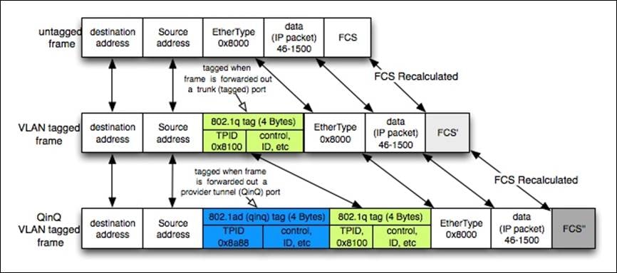
When a service provider offers services, each user’s network segmentation is preserved using Q-in-Q, also known as "double tagging" or "stacking VLANs”. This is a technique used to extend VLANs (Virtual LANs) across a transport network. It allows multiple customer VLANs to be tagged with a provider vlan, allowing service providers to offer Layer 2 VPN services to their customers. This allows customers to maintain their existing vlan structure while connecting to the service provider's network.
In a Q-in-Q deployment, customer frames are tagged with two vlan tags: a customer-facing vlan tag and a provider-facing vlan tag. The customer-facing vlan tag is used to identify the customer's vlan, while the provider-facing vlan tag is used to identify the provider's vlan. This allows the service provider to maintain the customer's vlan structure while connecting the customer's network to the provider's network. It can also be used to provide additional security by isolating customer VLANs from each other.
Introduction to VxLAN (Virtual extensible LAN)
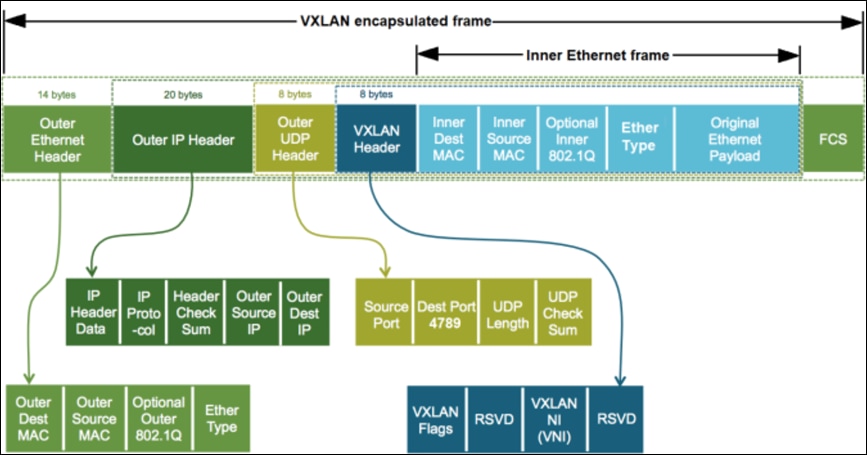
VxLAN (Virtual Extensible LAN) is a network virtualization technology that extends Layer 2 connections across a Layer 3 network. It uses a VxLAN header, which encapsulates the original Layer-2 frames, allowing them to be transmitted over a Layer 3 network. VxLAN ID (also known as the VxLAN Network Identifier or VNI) is a 24-bit identifier used to uniquely identify a virtual network.
The VxLAN ID in the header serves as the basis for building the VxLAN segment It is used to map the virtual network to a specific VxLAN segment, and to identify the destination of the traffic in the VxLAN network. All the endpoints that are part of the same VxLAN segment have the same VxLAN ID.
VxLAN addresses scalability limitations of traditional VLANs by allowing a large number of VLANs to be created. While traditional VLANs are limited to 4094, VxLANs can support up to 16 million unique VxLAN IDs (VNIs). This allows for a large number of virtual networks to be created, making it well suited for large-scale data center deployments.
This segmentation approach enables multi-tenancy by allowing different virtual networks to be isolated from each other, even if they are using the same physical infrastructure. This can be useful in a cloud computing environment, where different tenants may require their own virtual networks. Additionally, it can be useful where the network needs to be extended across multiple geographic locations, such as in disaster recovery scenarios.
Introduction to EVPN (Ethernet Virtual Private Network)
EVPN (Ethernet Virtual Private Network) is a control-plane technology that allows for the automatic discovery and configuration of virtual private networks (VPNs) using Multi-Protocol BGP (MP-BGP) routing protocol. It provides a way to exchange Layer 2 and Layer 3 information. The transport can be either VxLAN or MPLS. In this case study, VxLAN is used as a transport mechanism for the fabric infrastructure.
EVPN provides several benefits over traditional Layer 2 VPN technologies, including:
● Multi-homing support – EVPN allows for multiple links to be used for a single VPN, providing redundancy and high availability.
● Layer 3 and Layer 2 VPN services – EVPN supports both Layer 3 and Layer 2 VPN services, making it more versatile than traditional Layer 2 VPN technologies.
● Automatic discovery and configuration – EVPN uses a control-plane to automatically discover and configure VPNs, reducing the need for manual configuration and improving scalability.
● Interoperability – EVPN is designed to work with existing Layer 2 and Layer 3 protocols, making it easier to integrate into existing networks.
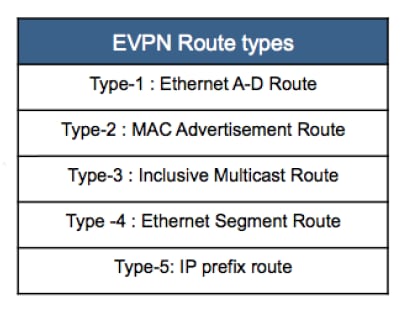
● EVPN can be used in different scenarios, such as data center interconnect, WAN connectivity, and service provider infrastructure. It can also be used in conjunction with VxLAN, which is known as VxLAN EVPN. This combination provides a way to extend Layer 2 connections across a Layer 3 network, while also providing the control-plane functionality using EVPN route types. EVPN route types are used to carry different types of information over the network. EVPN route types are carried in MP-BGP (Multiprotocol Border Gateway Protocol) updates and are used by the network's routing and switching equipment to make forwarding decisions.
Q-in-VNI with EVPN and VxLAN as transport
A TELCO service provider VxLAN fabric infrastructure is CLOS-based architecture with a Leaf and Spine layer switches. All the leaf nodes will be connected to all the spine switches but the spine switches will not be connected to each other. Each leaf node or node pair will act as VxLAN Tunnel Endpoint (VTEP). The traffic entering the fabric will have a fixed latency with 3 hop to reach the end service.
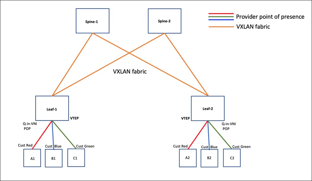
In the above figure the Service provider VxLAN fabric consists of 2 Leaf and 2 Spine Switches. The leaf switches are the point of presence for the service provider offering Q-in-Q services to customer Red, Blue and Green.
In this case study,
● Leaf1 and Leaf2 loopback addresses are advertised using OSPF routing protocol. The other recommended option is to use IS-IS as the Interior gateway protocol(IGP).
● On both Leaf switches, Loopback 1 is source interface for VxLAN NVE interface.
● BGP EVPN is configured between the Leaf and Spine nodes.
● Spine nodes act as the route reflector (RR) for the EVPN sessions.
● Customers Red, Blue, and green are configured with a unique Provider-vlan mapped to a unique layer2 VNI across the VxLAN fabric.
● On the local leaf node, every customer endpoint (MAC) received on an interface configured with a Provider-vlan, is learned and advertised using BGP EVPN as type-2 route (MAC-Route).
● This type-2 route will also contain layer2 VNI and the next hop information which is the VTEP IP address of the local leaf.
VxLAN EVPN fabric configuration sample shown below is from Leaf and Spine switches. Note that EVPN configuration under BGP when not explicitly configured, the route target for every VNI, import a,nd export will be set to auto by default.
Note: Partial configuration is shown below with few VLANs and VNIs but a few hundred VLANs and VNIs are used as part of this case study.
Table 1. VxLAN Configuration sample
| LEAF-1 Configuration |
LEAF-2 Configuration |
SPINE-1 Configuration |
| vlan Configuration vlan 1300 vn-segment 13000 vlan 1301 vn-segment 13001 vlan 1302 vn-segment 13002 BGP Configuration router bgp 65001 router-id 10.102.0.3 neighbor 10.102.0.1 remote-as 65001 update-source loopback0 address-family l2vpn evpn send-community send-community extended evpn OSPF Configuration router ospf UNDER router-id 10.102.0.3 interface loopback0 ip router ospf UNDER area 0.0.0.0 interface loopback1 ip router ospf UNDER area 0.0.0.0 interface Ethernet1/49 ip ospf network point-to-point ip router ospf UNDER area 0.0.0.0 VxLAN Configuration interface nve1 switch(config-if)# no shutdown host-reachability protocol bgp source-interface loopback1 member vni 13000 mcast-group 239.1.1.1 member vni 13001 mcast-group 239.1.1.1 member vni 13002 mcast-group 239.1.1.1 |
vlan Configuration vlan 1300 vn-segment 13000 vlan 1301 vn-segment 13001 vlan 1302 vn-segment 13002 BGP Configuration router bgp 65001 router-id 10.102.0.2 neighbor 10.102.0.1 remote-as 65001 update-source loopback0 address-family l2vpn evpn send-community send-community extended evpn OSPF Configuration router ospf UNDER router-id 10.102.0.2 interface loopback0 ip router ospf UNDER area 0.0.0.0 interface loopback1 ip router ospf UNDER area 0.0.0.0 interface Ethernet1/49 ip ospf network point-to-point ip router ospf UNDER area 0.0.0.0 VxLAN Configuration interface nve1 switch(config-if)# no shutdown host-reachability protocol bgp source-interface loopback1 member vni 13000 mcast-group 239.1.1.1 member vni 13001 mcast-group 239.1.1.1 member vni 13002 mcast-group 239.1.1.1 |
BGP Configuration router bgp 65001 router-id 10.102.0.1 neighbor 10.102.0.2 remote-as 65001 update-source loopback0 address-family l2vpn evpn send-community send-community extended route-reflector-client neighbor 10.102.0.3 remote-as 65001 update-source loopback0 address-family l2vpn evpn send-community send-community extended route-reflector-client OSPF Configuration router ospf UNDER router-id 10.102.0.1 interface loopback0 ip router ospf UNDER area 0.0.0.0 interface loopback254 ip router ospf UNDER area 0.0.0.0 interface Ethernet1/5 ip ospf network point-to-point ip router ospf UNDER area 0.0.0.0 interface Ethernet1/6 ip ospf network point-to-point ip router ospf UNDER area 0.0.0.0 |
The subsequent topics will cover various techniques used by service providers using Q-in-VNI over a VxLAN fabric as transport to provide VPN services.
Q-in-VNI allows you to categorize network traffic by assigning it to a specific port. In a multi-tenant setup, you can designate a port to a tenant/customer and transmit/receive data using the VxLAN overlay. The provider interface is configured as an access port that uses ‘switchport mode dot1q tunnel’, which receives a dot1q tagged packet from the customer switch. The VxLAN encapsulated packet holds the customer's VLAN tag in its inner frame's L2 header.
Interface configuration:
switch(config-if)# interface Ethernet1/51
switch(config-if)# description Q-in-VNI for Customer Red
switch(config-if)# switchport
switch(config-if)# switchport mode dot1q-tunnel
switch(config-if)# switchport access vlan 300
switch(config-if)# spanning-tree port type edge
switch(config-if)# spanning-tree bpdufilter enable
switch(config-if)# mtu 9216
switch(config-if)# no shutdown
switch(config-if)# interface Ethernet1/52
switch(config-if)# description Q-in-VNI for Customer Blue
switch(config-if)# switchport
switch(config-if)# switchport mode dot1q-tunnel
switch(config-if)# switchport access vlan 301
switch(config-if)# spanning-tree port type edge
switch(config-if)# spanning-tree bpdufilter enable
switch(config-if)# mtu 9216
switch(config-if)# no shutdown
switch(config)# vlan 300
switch(config-vlan)# vn-segment 33000
switch(config)# vlan 300
switch(config-vlan)# vn-segment 33001
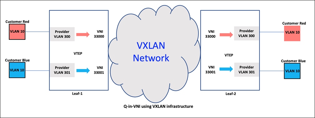
In the above figure, the user Red’s traffic is forwarded over a VxLAN overlay network, which uses VxLAN headers to encapsulate the original dot1q frame on VLAN 10. This allows the traffic to be transmitted over a layer-3 network, while preserving the original layer-2 information. The VxLAN header includes information such as the Source VTEP and Destination VTEP, as well as the layer-2 VNI, which is used to forward the traffic to its destination. When the traffic reaches the LEAF-2 switch, the VxLAN header is removed (decapsulated), and the original VLAN 10 frame is sent out on the other side. The user’s original frame is preserved throughout the journey, ensuring that the traffic is delivered to its intended destination intact.
Like user Red, user Blue communicates over VLAN 10, but it is configured as a Q-in-VNI port with provider VLAN 301 and a unique layer-2 VNI of 33001. The traffic is forwarded to the correct Q-in-VNI port-based on the matching provider VLAN 301. Despite having the same customer VLAN, each customer has a unique layer-2 VNI to ensure proper traffic forwarding and thereby maintaining multi tenancy.
A packet capture in the VxLAN fabric is shown below:
● SRC VTEP address 10.102.1.2 is LEAF-1 lo1 address (source-interface of NVE1 interface)
● DST VTEP address 10.102.1.1 is LEAF-2 lo1 address (source-interface of NVE1 interface)
● VxLAN packet UDP header DST Port is 4789
● Layer-2 VNI for Provider vlan 300 is 33000
● Encapsulated packet showing customer Red original packet with VLAN ID 10
● Capture also shows inner packet’s SRC IP 10.1.1.2 and DST IP address 10.1.1.1
[Protocols in frame: eth:ethertype:ip:udp:VxLAN:eth:ethertype:vlan:ethertype:ip:data]
Ethernet II, Src: a0:b4:39:0b:9e:0b, Dst: 00:fd:22:8d:1b:75
Destination: 00:fd:22:8d:1b:75
Address: 00:fd:22:8d:1b:75
Source: a0:b4:39:0b:9e:0b
Address: a0:b4:39:0b:9e:0b
Type: IPv4 (0x0800)
Internet Protocol Version 4, Src: 10.102.1.2, Dst: 10.102.1.1
0100 .... = Version: 4
.... 0101 = Header Length: 20 bytes (5)
Differentiated Services Field: 0xc0 (DSCP: CS6, ECN: Not-ECT)
1100 00.. = Differentiated Services Codepoint: Class Selector 6 (48)
.... ..00 = Explicit Congestion Notification: Not ECN-Capable Transport (0)
Flags: 0x0000
Fragment offset: 0
Time to live: 255
Protocol: UDP (17)
Source: 10.102.1.2
Destination: 10.102.1.1
User Datagram Protocol, Src Port: 13894, Dst Port: 4789
Source Port: 13894
Destination Port: 4789
Virtual eXtensible Local Area Network
Flags: 0x0800, VxLAN Network ID (VNI)
0... .... .... .... = GBP Extension: Not defined
.... .... .0.. .... = Don't Learn: False
.... 1... .... .... = VxLAN Network ID (VNI): True
.... .... .... 0... = Policy Applied: False
.000 .000 0.00 .000 = Reserved(R): 0x0000
Group Policy ID: 0
VxLAN Network Identifier (VNI): 33000
Reserved: 0
Ethernet II, Src: 00:45:50:01:00:01, Dst: 00:85:54:01:01:01
Destination: 00:85:54:01:01:01
Address: 00:85:54:01:01:01
Source: 00:45:50:01:00:01
Address: 00:45:50:01:00:01
Type: 802.1Q Virtual LAN (0x8100)
802.1Q Virtual LAN, PRI: 7, DEI: 0, ID: 10
111. .... .... .... = Priority: Network Control (7)
...0 .... .... .... = DEI: Ineligible
.... 0000 0000 1010 = ID: 10
Type: IPv4 (0x0800)
Internet Protocol Version 4, Src: 10.1.1.2, Dst: 10.1.1.1
0100 .... = Version: 4
.... 0101 = Header Length: 20 bytes (5)
Differentiated Services Field: 0xc0 (DSCP: CS6, ECN: Not-ECT)
1100 00.. = Differentiated Services Codepoint: Class Selector 6 (48)
.... ..00 = Explicit Congestion Notification: Not ECN-Capable Transport (0)
Time to live: 255
Protocol: Unknown (253)
Header checksum: 0xdab1 [validation disabled]
[Header checksum status: Unverified]
Source: 10.1.1.2
Destination: 10.1.1.1
Selective Q-in-VNI with multiple provider VLANs
Selective Q-in-VNI is a VxLAN tunneling feature that allows a user-specific VLAN or range of user VLANs on a port to be associated with one specific provider VLAN. Packets that come in with a VLAN tag that matches any of the configured user VLANs on the port are tunneled across the VxLAN fabric using the properties of the service provider VNI mapped to the provider VLAN in the configuration. The VxLAN encapsulated packet carries the user VLAN tag as part of the L2 header of the inner frame.
The packets with a VLAN tag that is not present in the range of the configured user VLANs on a selective Q-in-VNI configured port are dropped. This includes the packets with a VLAN tag that matches the native VLAN on the port. A range of customer VLANs can also be selectively mapped to a single provider VLAN as shown in the configuration sample below.
Note: See limitations for native VLAN while configuring selective Q-in-VNI given in the reference section at the end of the document.
Interface configuration sample:
switch# config terminal
switch(config-if)# interface Ethernet1/52
switch(config-if)# description Selective Q-in-VNI with multiple provider Vlans
switch(config-if)# switchport
switch(config-if)# switchport mode trunk
switch(config-if)# switchport vlan mapping 10 dot1q-tunnel 100
switch(config-if)# switchport vlan mapping 11 dot1q-tunnel 101
switch(config-if)# switchport vlan mapping 12 dot1q-tunnel 102
.
..
...
switch(config-if)# switchport vlan mapping 58 dot1q-tunnel 148
switch(config-if)# switchport vlan mapping 59 dot1q-tunnel 149
switch(config-if)# switchport vlan mapping 800-820 dot1q-tunnel 150
switch(config-if)# switchport vlan mapping 821-840 dot1q-tunnel 151
switch(config-if)# switchport trunk allowed vlan 100-149,150,151
switch(config-if)# spanning-tree port type edge trunk
switch(config-if)# spanning-tree bpdufilter enable
switch(config-if)# mtu 9216
switch(config-if)# no shutdown
switch# config terminal
switch(config) vlan 100
switch(config-vlan) vn-segment 30000
switch(config) vlan 101
switch(config-vlan) vn-segment 30001
switch(config) vlan 102
switch(config-vlan) vn-segment 30002
.
..
...
switch(config) vlan 120
switch(config-vlan) vn-segment 30020
switch(config) vlan 121
switch(config-vlan) vn-segment 30021
switch(config) vlan 122
switch(config-vlan) vn-segment 30022
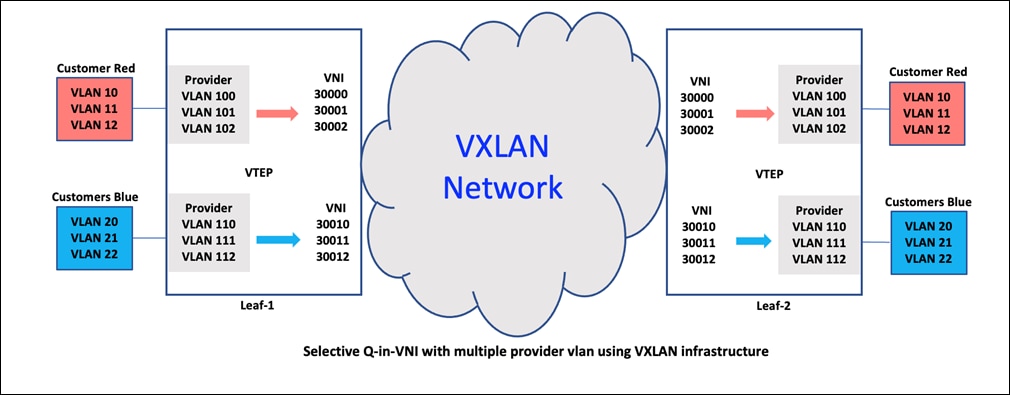
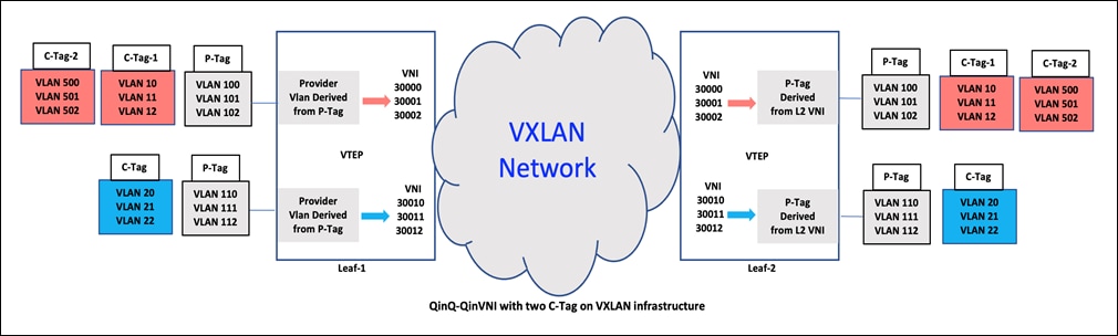
In the above figure, the service provider switch is set up to map user VLAN 10 to provider VLAN 100, ensuring that traffic is forwarded to the correct destination. The VxLAN header includes the layer-2 VNI, in this case is 30000, which is used to route traffic over the network with the source VTEP Leaf-1 and destination VTEP Leaf-2. The encapsulation and decapsulation process is performed at each VTEP, ensuring that the original user frame remains intact as it travels over the VxLAN fabric. At the LEAF-2 switch, the VxLAN header is removed, and the inner frame (VLAN 10) is sent out on the egress side, facing the user. This allows the user Red's original frame to be preserved and delivered without any modifications, ensuring seamless and reliable communication over the network.
Similarly, user VLAN 11 is mapped to provider VLAN 101 with Layer-2 VNI 30001 and user VLAN 20 to provider VLAN 110 with Layer-2 VNI 30010, based on the configuration of the interface. This selective mapping of user VLANs to Q-in-VNI maintains multi-tenancy over the VxLAN network. In summary, each port on the service provider's switch can accommodate multiple customer VLANs, each connected to a distinct provider VLAN with a unique layer-2 VNI. This directs traffic to the correct Q-in-VNI port, making efficient network communication.
Packet capture in the VxLAN fabric is shown below,
● SRC VTEP address 10.102.1.2 is LEAF-1 lo1 address (source-interface of NVE1 interface)
● DST VTEP address 10.102.1.1 is LEAF-2 lo1 address (source-interface of NVE1 interface)
● VxLAN packet UDP header DST Port is 4789
● Layer-2 VNI for Provider vlan 30002, which provider VLAN 102
● Encapsulated packet showing customer Red inner frame with VLAN ID 12
● Inner frames seen with SRC IP 102.1.1.2 and DST IP address 102.1.1.1
[Protocols in frame: eth:ethertype:ip:udp:VxLAN:eth:ethertype:vlan:ethertype:ip:data]
Ethernet II, Src: a0:b4:39:0b:9e:0b, Dst: 00:fd:22:8d:1b:75
Destination: 00:fd:22:8d:1b:75
Address: 00:fd:22:8d:1b:75
Source: a0:b4:39:0b:9e:0b
Address: a0:b4:39:0b:9e:0b
Type: IPv4 (0x0800)
Internet Protocol Version 4, Src: 10.102.1.2, Dst: 10.102.1.1
0100 .... = Version: 4
.... 0101 = Header Length: 20 bytes (5)
Differentiated Services Field: 0xc0 (DSCP: CS6, ECN: Not-ECT)
1100 00.. = Differentiated Services Codepoint: Class Selector 6 (48)
.... ..00 = Explicit Congestion Notification: Not ECN-Capable Transport (0)
Flags: 0x0000
Fragment offset: 0
Time to live: 255
Protocol: UDP (17)
Source: 10.102.1.2
Destination: 10.102.1.1
User Datagram Protocol, Src Port: 21413, Dst Port: 4789
Source Port: 21413
Destination Port: 4789
Virtual eXtensible Local Area Network
Flags: 0x0800, VxLAN Network ID (VNI)
0... .... .... .... = GBP Extension: Not defined
.... .... .0.. .... = Don't Learn: False
.... 1... .... .... = VxLAN Network ID (VNI): True
.... .... .... 0... = Policy Applied: False
.000 .000 0.00 .000 = Reserved(R): 0x0000
Group Policy ID: 0
VxLAN Network Identifier (VNI): 30002
Reserved: 0
Ethernet II, Src: 00:51:54:02:01:01, Dst: 00:85:56:02:01:02
Destination: 00:85:56:02:01:02
Address: 00:85:56:02:01:02
Source: 00:51:54:02:01:01
Address: 00:51:54:02:01:01
Type: 802.1Q Virtual LAN (0x8100)
802.1Q Virtual LAN, PRI: 7, DEI: 0, ID: 12
111. .... .... .... = Priority: Network Control (7)
...0 .... .... .... = DEI: Ineligible
.... 0000 0000 1100 = ID: 12
Type: IPv4 (0x0800)
Internet Protocol Version 4, Src: 102.1.1.2, Dst: 102.1.1.1
0100 .... = Version: 4
.... 0101 = Header Length: 20 bytes (5)
Differentiated Services Field: 0xc0 (DSCP: CS6, ECN: Not-ECT)
1100 00.. = Differentiated Services Codepoint: Class Selector 6 (48)
.... ..00 = Explicit Congestion Notification: Not ECN-Capable Transport (0)
Total Length: 490
Identification: 0x8774 (34676)
Flags: 0x0000
Fragment offset: 0
Time to live: 255
Protocol: Unknown (253)
Source: 102.1.1.2
Destination: 102.1.1.1
VLAN mapping is the method of connecting a user VLAN to a service provider VLAN. In certain situations, VLAN translation may be necessary, such as when multiple users connect to the same physical switch using the same VLAN encapsulation but should not present on the same layer 2 segments. In these cases, the incoming VLAN is translated to a unique VLAN in the VxLAN fabric which is mapped to a VNI to extend the segment.
In this case study, the user VLAN 1000 is mapped to the provider VLAN 1300 on the interface. The provider VLAN 1300 has a layer-2 VNI of 13000.
Interface configuration showing multiple user VLANs mapped to translated provider VLANs:
switch# config terminal
switch(config-if)# interface Ethernet1/53
switch(config-if)# description Port Vlan Mapping
switch(config-if)# switchport
switch(config-if)# switchport mode trunk
switch(config-if)# switchport vlan mapping enable
switch(config-if)# switchport vlan mapping 1000 1300
switch(config-if)# switchport vlan mapping 1001 1301
switch(config-if)# switchport vlan mapping 1002 1302
switch(config-if)# switchport vlan mapping 1003 1303
switch(config-if)# switchport vlan mapping 1004 1304
.
..
...
switch(config-if)# switchport vlan mapping 1194 1494
switch(config-if)# switchport vlan mapping 1195 1495
switch(config-if)# switchport vlan mapping 1196 1496
switch(config-if)# switchport vlan mapping 1197 1497
switch(config-if)# switchport vlan mapping 1198 1498
switch(config-if)# switchport vlan mapping 1199 1499
switch(config-if)# switchport trunk allowed vlan 1300-1499
switch(config-if)# no shutdown
switch# config terminal
switch(config) vlan 1300
switch(config-vlan) vn-segment 13000
switch(config) vlan 1301
switch(config-vlan) vn-segment 13001
switch(config) vlan 1302
switch(config-vlan) vn-segment 13002
switch(config) vlan 1303
switch(config-vlan) vn-segment 13003
switch(config) vlan 1310
.
..
...
switch(config-vlan) vn-segment 13010
switch(config) vlan 1311
switch(config-vlan) vn-segment 13011
switch(config) vlan 1312
switch(config-vlan) vn-segment 13012
Vlan mapping with one Customer Tag
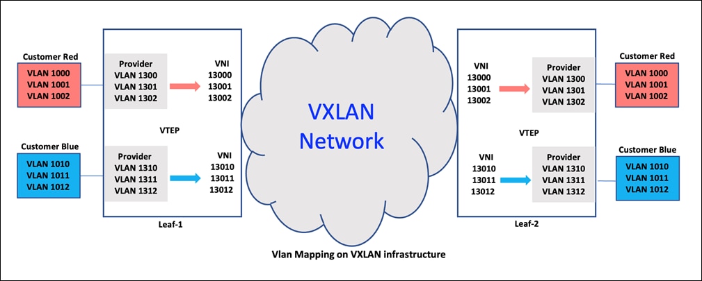
In the above figure, the user VLANs 1000, 1001, 1002, and so on are mapped to provider VLANs 1300, 1301, 1302, respectively. The user is connected to a service provider switch set up as a VLAN-mapped Q-in-VNI port. User VLAN 1000 is mapped to provider VLAN 1300 which is configured with a layer-2 VNI of 13000.
When traffic on VLAN 1000 reaches the interface, it is encapsulated with a VxLAN header that includes layer-2 VNI 13000. This is because the interface is set up to translate user VLAN 1000 to provider VLAN 1300. The VxLAN header has a source VTEP address of the LEAF-1 switch and a destination VTEP address of the LEAF-2 switch. The packet is then sent to LEAF-2, where the VxLAN header is removed and the inner frame (on VLAN 1000) is sent out on the egress side facing the user.
This process ensures that the user VLAN 1000 traffic is preserved and transmitted securely between the LEAF-1 and LEAF-2 switches through the VxLAN fabric. The VxLAN header adds an extra layer of abstraction to the original user VLAN 1000 frame, allowing it to traverse the network and reach its destination, where the header is then removed, and the original frame is delivered to the user. This VxLAN-based approach enables efficient and secure communication between user VLANs and provider VLANs while preserving the user's original VLAN information.
A packet capture in the VxLAN fabric is shown below,
● SRC VTEP address 10.102.1.2 is LEAF-1 lo1 address (source-interface of NVE1 interface)
● DST VTEP address 10.102.1.1 is LEAF-2 lo1 address (source-interface of NVE1 interface)
● VxLAN packet UDP header DST Port is 4789
● Note that vlan 1000 which is translated is not seen packet capture
● Provider VLAN 1300, which is translated VLANs Layer-2 VNI 13000 seen
● Inner frames SRC IP 10.100.1.2 and DST IP address 10.100.1.1
[Protocols in frame: eth:ethertype:ip:udp:VxLAN:eth:ethertype:ip:data]
Ethernet II, Src: a0:b4:39:0b:9e:0b, Dst: 00:fd:22:8d:1b:75
Destination: 00:fd:22:8d:1b:75
Address: 00:fd:22:8d:1b:75
Source: a0:b4:39:0b:9e:0b
Address: a0:b4:39:0b:9e:0b
Type: IPv4 (0x0800)
Internet Protocol Version 4, Src: 10.102.1.2, Dst: 10.102.1.1
0100 .... = Version: 4
.... 0101 = Header Length: 20 bytes (5)
Differentiated Services Field: 0xc0 (DSCP: CS6, ECN: Not-ECT)
1100 00.. = Differentiated Services Codepoint: Class Selector 6 (48)
.... ..00 = Explicit Congestion Notification: Not ECN-Capable Transport (0)
Flags: 0x0000
Fragment offset: 0
Time to live: 255
Protocol: UDP (17)
Source: 10.102.1.2
Destination: 10.102.1.1
User Datagram Protocol, Src Port: 42297, Dst Port: 4789
Source Port: 42297
Destination Port: 4789
tual eXtensible Local Area Network
Flags: 0x0800, VxLAN Network ID (VNI)
0... .... .... .... = GBP Extension: Not defined
.... .... .0.. .... = Don't Learn: False
.... 1... .... .... = VxLAN Network ID (VNI): True
.... .... .... 0... = Policy Applied: False
.000 .000 0.00 .000 = Reserved(R): 0x0000
Group Policy ID: 0
VxLAN Network Identifier (VNI): 13000
Reserved: 0
Ethernet II, Src: 00:55:53:03:03:b9, Dst: 00:85:54:03:02:f1
Destination: 00:85:54:03:02:f1
Address: 00:85:54:03:02:f1
Source: 00:55:53:03:03:b9
Address: 00:55:53:03:03:b9
Type: IPv4 (0x0800)
Internet Protocol Version 4, Src: 10.100.1.2, Dst: 10.100.1.1
0100 .... = Version: 4
.... 0101 = Header Length: 20 bytes (5)
Differentiated Services Field: 0xc0 (DSCP: CS6, ECN: Not-ECT)
1100 00.. = Differentiated Services Codepoint: Class Selector 6 (48)
.... ..00 = Explicit Congestion Notification: Not ECN-Capable Transport (0)
Total Length: 490
Identification: 0x6f4f (28495)
Flags: 0x0000
Fragment offset: 0
Time to live: 255
Protocol: Unknown (253)
Source: 10.100.1.2
Destination: 10.100.1.1
Q-in-VNI Vlan mapping with two Customer Tag
In the packet capture shown below, user traffic was simulated with two C-Tags (i.e. two VLAN tags). The inner tag is VLAN 600, and the outer tag is VLAN 1000. According to the configuration, outer VLAN 1000 is mapped to provider VLAN 1300.
Packet capture in the VxLAN fabric is shown below:
● SRC VTEP address 10.102.1.2 is LEAF-1 lo1 address (source-interface of NVE1 interface)
● DST VTEP address 10.102.1.1 is LEAF-2 lo1 address (source-interface of NVE1 interface)
● VxLAN packet UDP header DST Port is 4789
● Note that VLAN 1000 which is translated is not seen packet capture
● Provider VLAN 1300, which is translated VLANs Layer-2 VNI 13000 seen
● Second user VLAN 600 is preserved inside the VxLAN packet.
● Inner frames seen with SRC IP 60.1.1.2 and DST IP address 60.1.1.1
Frame 1: 554 bytes on wire (4432 bits), 554 bytes captured (4432 bits) on interface ps-inb, id 0
[Protocols in frame: eth:ethertype:ip:udp:VxLAN:eth:ethertype:vlan:ethertype:ip:data]
Ethernet II, Src: a0:b4:39:0b:9e:0b, Dst: 00:fd:22:8d:1b:75
Destination: 00:fd:22:8d:1b:75
Address: 00:fd:22:8d:1b:75
Source: a0:b4:39:0b:9e:0b
Address: a0:b4:39:0b:9e:0b
Type: IPv4 (0x0800)
Internet Protocol Version 4, Src: 10.102.1.2, Dst: 10.102.1.1
0100 .... = Version: 4
.... 0101 = Header Length: 20 bytes (5)
Differentiated Services Field: 0xc0 (DSCP: CS6, ECN: Not-ECT)
1100 00.. = Differentiated Services Codepoint: Class Selector 6 (48)
.... ..00 = Explicit Congestion Notification: Not ECN-Capable Transport (0)
Flags: 0x0000
Fragment offset: 0
Time to live: 255
Protocol: UDP (17)
Source: 10.102.1.2
Destination: 10.102.1.1
User Datagram Protocol, Src Port: 50138, Dst Port: 4789
Source Port: 50138
Destination Port: 4789
Virtual eXtensible Local Area Network
Flags: 0x0800, VxLAN Network ID (VNI)
0... .... .... .... = GBP Extension: Not defined
.... .... .0.. .... = Don't Learn: False
.... 1... .... .... = VxLAN Network ID (VNI): True
.... .... .... 0... = Policy Applied: False
.000 .000 0.00 .000 = Reserved(R): 0x0000
Group Policy ID: 0
VxLAN Network Identifier (VNI): 13000
Reserved: 0
Ethernet II, Src: 00:10:aa:00:04:85, Dst: 00:10:bb:00:04:86
Destination: 00:10:bb:00:04:86
Address: 00:10:bb:00:04:86
Source: 00:10:aa:00:04:85
Address: 00:10:aa:00:04:85
Type: 802.1Q Virtual LAN (0x8100)
802.1Q Virtual LAN, PRI: 7, DEI: 0, ID: 600
111. .... .... .... = Priority: Network Control (7)
...0 .... .... .... = DEI: Ineligible
.... 0010 0101 1000 = ID: 600
Type: IPv4 (0x0800)
Internet Protocol Version 4, Src: 60.1.1.2, Dst: 60.1.1.1
0100 .... = Version: 4
.... 0101 = Header Length: 20 bytes (5)
Differentiated Services Field: 0xc0 (DSCP: CS6, ECN: Not-ECT)
1100 00.. = Differentiated Services Codepoint: Class Selector 6 (48)
.... ..00 = Explicit Congestion Notification: Not ECN-Capable Transport (0)
Total Length: 486
Identification: 0x13b8 (5048)
Flags: 0x0000
Fragment offset: 0
Time to live: 255
Protocol: Unknown (253)
Source: 60.1.1.2
Destination: 60.1.1.1
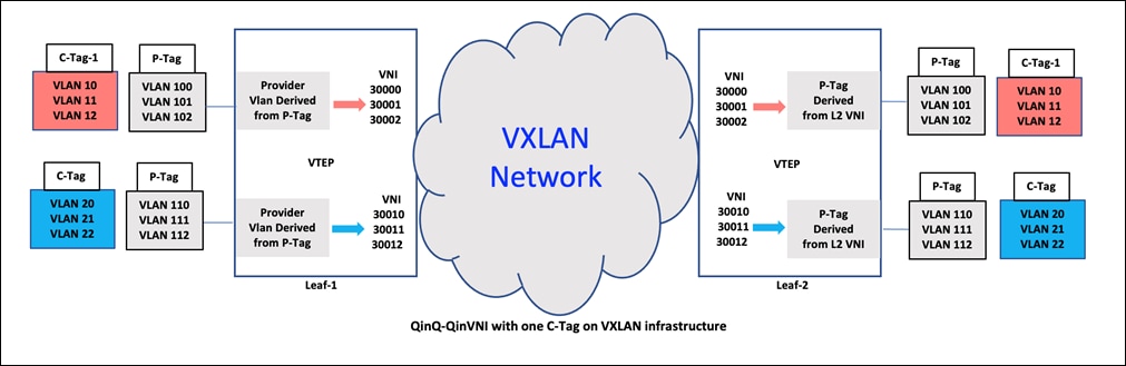
QinQ-QinVNI can provide an even greater level of network segmentation and flexibility. For example, a single physical network could have multiple Q-in-Q VLANs running, each with its own set of virtual networks created using Q-in-VNI. This allows for a high degree of isolation between different groups of users or applications, while still allowing them to share the same physical infrastructure.
Additionally, QinQ-QinVNI can also be used to create virtual network overlays, which can be used to extend the reach of virtual networks across multiple physical locations, such as in a multi-tenant data center or cloud environment. This allows for more efficient use of resources and greater flexibility in managing and scaling virtual networks.
Overall, the combination of QinQ-QinVNI can provide a powerful toolset for network administrators to create, manage, and scaled virtual networks in a variety of different environments.
In this case study, there are two VLAN tags. The outer VLAN tag is the provider VLAN that maps to the layer-2 VNI in the VXLAN fabric. The inner VLAN has the user VLAN which is transparent to the interface configuration and the VXLAN fabric and is kept intact. The multi-tag allows multiple provider VLANs on the same physical interface as shown below.
QinQ-QinVNI Multi tag with one Customer Tag
Interface configuration sample:
switch# config terminal
switch(config-if)# interface Ethernet1/54
switch(config-if)# description Q-in-Q to Q-in-VNI
switch(config-if)# switchport
switch(config-if)# switch(config-if)# switchport mode trunk
switch(config-if)# switch(config-if)# switchport trunk allow-multi-tag
switch(config-if)# switchport trunk allowed vlan 50,100-149,300-301,1300-1499
switch(config-if)# spanning-tree port type edge trunk
switch(config-if)# mtu 9216
switch(config-if)# no shutdown
switch# config terminal
switch(config) vlan 100
switch(config-vlan) vn-segment 30000
switch(config) vlan 101
switch(config-vlan) vn-segment 30001
switch(config) vlan 102
switch(config-vlan) vn-segment 30002
switch(config) vlan 110
.
..
...
switch(config-vlan) vn-segment 30010
switch(config) vlan 111
switch(config-vlan) vn-segment 30011
switch(config) vlan 112
switch(config-vlan) vn-segment 30012
Packet capture in the VxLAN fabric is shown below:
● SRC VTEP address 10.102.1.2 is LEAF-1 lo1 address (source-interface of NVE1 interface)
● DST VTEP address 10.102.1.1 is LEAF-2 lo1 address (source-interface of NVE1 interface)
● VxLAN packet UDP header DST Port is 4789
● Provider VLAN 100, Layer-2 VNI 30000 is used for forwarding this traffic
● Customer VLAN 10 is preserved inside the VxLAN packet.
● Inner frames seen with SRC IP 100.1.1.1 and DST IP address 100.1.1.2
[Protocols in frame: eth:ethertype:ip:udp:VxLAN:eth:ethertype:vlan:ethertype:ip:data]
Ethernet II, Src: a0:b4:39:0b:a2:57, Dst: 00:fd:22:8d:1b:75
Destination: 00:fd:22:8d:1b:75
Address: 00:fd:22:8d:1b:75
Source: a0:b4:39:0b:a2:57
Address: a0:b4:39:0b:a2:57
Type: IPv4 (0x0800)
Internet Protocol Version 4, Src: 10.102.1.1, Dst: 10.102.1.2
0100 .... = Version: 4
.... 0101 = Header Length: 20 bytes (5)
Differentiated Services Field: 0xc0 (DSCP: CS6, ECN: Not-ECT)
1100 00.. = Differentiated Services Codepoint: Class Selector 6 (48)
.... ..00 = Explicit Congestion Notification: Not ECN-Capable Transport (0)
Total Length: 540
Identification: 0x55aa (21930)
Flags: 0x0000
Fragment offset: 0
Time to live: 255
Protocol: UDP (17)
Source: 10.102.1.1
Destination: 10.102.1.2
User Datagram Protocol, Src Port: 29571, Dst Port: 4789
Source Port: 29571
Destination Port: 4789
Virtual eXtensible Local Area Network
Flags: 0x0800, VxLAN Network ID (VNI)
0... .... .... .... = GBP Extension: Not defined
.... .... .0.. .... = Don't Learn: False
.... 1... .... .... = VxLAN Network ID (VNI): True
.... .... .... 0... = Policy Applied: False
.000 .000 0.00 .000 = Reserved(R): 0x0000
Group Policy ID: 0
VxLAN Network Identifier (VNI): 30000
Reserved: 0
Ethernet II, Src: 00:85:54:02:01:02, Dst: 00:51:52:02:01:01
Destination: 00:51:52:02:01:01
Address: 00:51:52:02:01:01
Source: 00:85:54:02:01:02
Address: 00:85:54:02:01:02
Type: 802.1Q Virtual LAN (0x8100)
802.1Q Virtual LAN, PRI: 7, DEI: 0, ID: 10
111. .... .... .... = Priority: Network Control (7)
...0 .... .... .... = DEI: Ineligible
.... 0000 0000 1010 = ID: 10
Type: IPv4 (0x0800)
Internet Protocol Version 4, Src: 100.1.1.1, Dst: 100.1.1.2
0100 .... = Version: 4
.... 0101 = Header Length: 20 bytes (5)
Differentiated Services Field: 0xc0 (DSCP: CS6, ECN: Not-ECT)
1100 00.. = Differentiated Services Codepoint: Class Selector 6 (48)
.... ..00 = Explicit Congestion Notification: Not ECN-Capable Transport (0)
Total Length: 486
Identification: 0xef59 (61273)
Flags: 0x0000
Fragment offset: 0
Time to live: 255
Protocol: Unknown (253)
Source: 100.1.1.1
Destination: 100.1.1.2
QinQ-QinVNI Multi tag with two Customer Tag
As discussed above, in this case, Q-in-VNI port is shown in the packet capture, sending traffic to another Q-in-VNI port with two user VLAN tags: outer VLAN 10 and inner VLAN 500. The provider VLAN for the Q-in-VNI is 100, which is mapped to layer-2 VNI 30000. The packet capture displays both the outer and inner user VLANs, as well as the layer-2 VNI 30000. Again both the user VLANs are retained inside the fabric.
Interface Configuration is the same as the previous one:
switch# config terminal
switch(config-if)# interface Ethernet1/54
switch(config-if)# description Q-in-Q to Q-in-VNI
switch(config-if)# switchport
switch(config-if)# switch(config-if)# switchport mode trunk
switch(config-if)# switch(config-if)# switchport trunk allow-multi-tag
switch(config-if)# switchport trunk allowed vlan 50,100-149,300-301,1300-1499
switch(config-if)# spanning-tree port type edge trunk
switch(config-if)# mtu 9216
switch(config-if)# no shutdown
switch# config terminal
switch(config) vlan 100
switch(config-vlan) vn-segment 30000
switch(config) vlan 300
switch(config-vlan) vn-segment 33000
switch(config) vlan 301
switch(config-vlan) vn-segment 33001
Packet capture in the VxLAN fabric is shown below,
● SRC VTEP address 10.102.1.2 is LEAF-1 lo1 address (source-interface of NVE1 interface)
● DST VTEP address 10.102.1.1 is LEAF-2 lo1 address (source-interface of NVE1 interface)
● VxLAN packet UDP header DST Port is 4789
● Provider VLAN 300, Layer-2 VNI 33000 is used for forwarding this traffic
● User VLAN 10, first C-tag is preserved inside the VxLAN packet.
● User VLAN 500, Second C-tag is also preserved inside the VxLAN packet.
● Inner frames seen with SRC IP 10.1.1.1 and DST IP address 10.1.1.2
[Protocols in frame: eth:ethertype:ip:udp:vxlan:eth:ethertype:vlan:ethertype:vlan:ethertype:arp]
Ethernet II, Src: a0:b4:39:0b:a2:57, Dst: 00:fd:22:8d:1b:75
Destination: 00:fd:22:8d:1b:75
Address: 00:fd:22:8d:1b:75
Source: a0:b4:39:0b:a2:57
Address: a0:b4:39:0b:a2:57
Type: IPv4 (0x0800)
Internet Protocol Version 4, Src: 10.102.1.1, Dst: 10.102.1.2
0100 .... = Version: 4
.... 0101 = Header Length: 20 bytes (5)
Differentiated Services Field: 0xe0 (DSCP: CS7, ECN: Not-ECT)
1110 00.. = Differentiated Services Codepoint: Class Selector 7 (56)
.... ..00 = Explicit Congestion Notification: Not ECN-Capable Transport (0)
Flags: 0x0000
Fragment offset: 0
Time to live: 255
Protocol: UDP (17)
Source: 10.102.1.1
Destination: 10.102.1.2
User Datagram Protocol, Src Port: 53720, Dst Port: 4789
Source Port: 53720
Destination Port: 4789
Virtual eXtensible Local Area Network
Flags: 0x0800, VXLAN Network ID (VNI)
0... .... .... .... = GBP Extension: Not defined
.... .... .0.. .... = Don't Learn: False
.... 1... .... .... = VXLAN Network ID (VNI): True
.... .... .... 0... = Policy Applied: False
.000 .000 0.00 .000 = Reserved(R): 0x0000
Group Policy ID: 0
VXLAN Network Identifier (VNI): 33000
Reserved: 0
Ethernet II, Src: 00:bb:94:00:04:89, Dst: 00:bb:94:00:04:88
Destination: 00:bb:94:00:04:88
Address: 00:bb:94:00:04:88
Source: 00:bb:94:00:04:89
Address: 00:bb:94:00:04:89
Type: 802.1Q Virtual LAN (0x8100)
802.1Q Virtual LAN, PRI: 7, DEI: 0, ID: 10
111. .... .... .... = Priority: Network Control (7)
...0 .... .... .... = DEI: Ineligible
.... 0000 0000 1010 = ID: 10
Type: 802.1Q Virtual LAN (0x8100)
802.1Q Virtual LAN, PRI: 7, DEI: 0, ID: 500
111. .... .... .... = Priority: Network Control (7)
...0 .... .... .... = DEI: Ineligible
.... 0001 1111 0100 = ID: 500
Type: ARP (0x0806)
Trailer: 00000000000000000000
Address Resolution Protocol (reply)
Hardware type: Ethernet (1)
Protocol type: IPv4 (0x0800)
Hardware size: 6
Protocol size: 4
Opcode: reply (2)
Sender MAC address: 00:bb:94:00:04:89
Sender IP address: 10.1.1.1
Target MAC address: 00:bb:94:00:04:88
Target IP address: 10.1.1.2
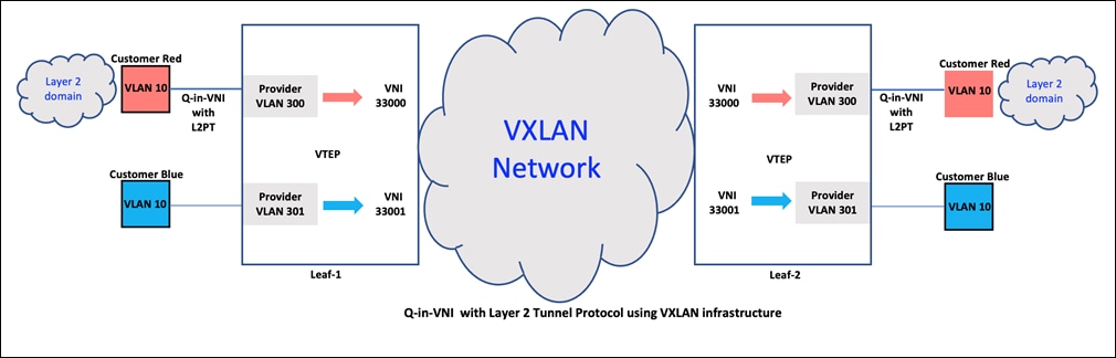
QinVNI with Layer 2 Protocol Tunneling
Layer 2 Protocol Tunneling is the process of encapsulating a Layer 2 (L2) protocol within a different L2 protocol, so that it can be transmitted over a network that does not support the original L2 protocol. It is aimed to extend the reach of L2 protocols over networks that would otherwise not support them, by encapsulating the protocol in a compatible format.
Spanning Tree Protocol (STP), VLAN Trunking Protocol (VTP), Link Layer Discovery Protocol (LLDP), and Cisco Discovery Protocol (CDP) are all Layer 2 protocols that can be tunneled. These protocols are typically used to manage the behavior and configuration of switches in a local area network (LAN), and tunneling them can enable their use over networks that would not otherwise support them.
Tunneling these protocols can help to maintain consistency and manageability of the network, even when the network is spread across multiple physical locations or spans multiple underlying networking technologies.
Interface configuration sample:
switch(config-if)# interface Ethernet1/51
switch(config-if)# description Q-in-VNI for Customer Red
switch(config-if)# switchport
switch(config-if)# switchport mode dot1q-tunnel
switch(config-if)# switchport access vlan 300
switch(config-if)# spanning-tree port type edge
switch(config-if)# l2protocol tunnel cdp
switch(config-if)# l2protocol tunnel stp
switch(config-if)# l2protocol tunnel vtp
switch(config-if)# l2protocol tunnel lldp
switch(config-if)# mtu 9216
switch(config-if)# no shutdown
switch# config terminal
switch(config) vlan 300
switch(config-vlan) vn-segment 33000
switch# show l2protocol tunnel
COS for Encapsulated Packets: 5
Shutdown Drop Encapsulation Decapsulation Drop
Port Protocol Threshold Threshold Counter Counter Counter
-------- -------- --------- --------- ------------- ------------- -------------
Eth1/51 cdp ---- ---- 0 0 0
stp ---- ---- 152 0 0
vtp ---- ---- 0 0 0
lldp ---- ---- 11 0 0
---- ---- ---- ---- ---- ----
---------- ---- ---- ---- ---- ----
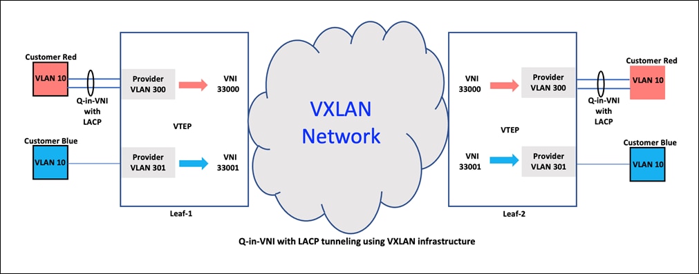
Q-in-VNI with LACP Tunneling
LACP (Link Aggregation Control Protocol) tunneling over VxLAN is a method for transmitting LACP frames over a VxLAN network. LACP is used to bundle multiple physical links together to form a single logical link, providing increased bandwidth and redundancy.
When LACP is tunneled over VxLAN, LACP frames are encapsulated within VxLAN frames and transmitted over the VxLAN network. This allows LACP to be used to manage link aggregation in networks that use VxLAN as the underlying technology.
Tunneling LACP over VxLAN can be beneficial in large, geographically dispersed networks where multiple physical locations are connected over VxLAN. By encapsulating LACP frames within VxLAN frames, the protocol can be used to manage link aggregation across the WAN, helping to ensure high availability and resiliency of the network.
Interface configuration sample:
switch# config terminal
switch(config)# interface ethernet 1/51
switch(config-if)# switchport mode dot1q-tunnel
switch(config-if)# switchport access vlan 10
switch(config-if)# spanning-tree bpdufilter enable
switch(config-if)# l2protocol tunnel lacp
switch(config-if)# interface nve1
switch(config-if)# overlay-encapsulation vxlan-with-tag tunnel-control-frames
switch# show l2protocol tunnel
COS for Encapsulated Packets: 5
Shutdown Drop Encapsulation Decapsulation Drop
Port Protocol Threshold Threshold Counter Counter Counter
-------- -------- --------- --------- ------------- ------------- -------------
Eth1/51 cdp ---- ---- 0 0 0
stp ---- ---- 0 0 0
vtp ---- ---- 0 0 0
lldp ---- ---- 0 0 0
lacp ---- ---- 0 0 0
---------- ---- ---- ---- ---- ----
Cisco Configuration Guide for Q-in-VNI on NX-OS Release 10.3(x)
Note: All guidelines and limitations when using Q-in-VNI on various nexus platforms is listed in the above URL.
VXLAN Design with Cisco Nexus 9300 Platform Switches
VXLAN Network with MP-BGP EVPN Control Plane Design Guide
Cisco Press: Building Data Centers with VXLAN BGP EVPN: A Cisco NX-OS Perspective
https://www.ciscopress.com/store/building-data-centers-with-vxlan-bgp-evpn-a-cisco-nx-9781587144677
Configuring VXLAN BGP EVPN
Configuring VxLAN Multisite
Cisco and the Cisco logo are trademarks or registered trademarks of Cisco and/or its affiliates in the U.S. and other countries. To view a list of Cisco trademarks, go to this URL: www.cisco.com/go/trademarks. Third-party trademarks mentioned are the property of their respective owners. The use of the word partner does not imply a partnership relationship between Cisco and any other company. (1721R)
Any Internet Protocol (IP) addresses and phone numbers used in this document are not intended to be actual addresses and phone numbers. Any examples, command display output, network topology diagrams, and other figures included in the document are shown for illustrative purposes only. Any use of actual IP addresses or phone numbers in illustrative content is unintentional and coincidental.
© 2023 Cisco Systems, Inc. All rights reserved.