New and Changed Information
The following table provides an overview of the significant changes up to this current release. The table does not provide an exhaustive list of all changes or of the new features up to this release.
|
Release Version |
Feature |
Description |
|---|---|---|
|
Support for multiple frontend IP addresses for Azure network load balancer |
This release provides support for multiple frontend IP addresses for the Azure network load balancer in Cisco Cloud APIC and Nexus Dashboard Orchestrator. |
Understanding Configurations for Multiple Frontend IP Addresses on the Azure Network Load Balancer
The following sections provide information on support for multiple frontend IP addresses on the Azure Network Load Balancer that is available beginning with Cisco Cloud APIC release 25.0(3) and Nexus Dashboard Orchestrator release 3.7(1).
About Azure Network Load Balancers
An Azure Network Load Balancer (also known as Azure Load Balancer) is a Layer 4 device that distributes the in-bound flow packets based on Layer 4 ports.
There are two ways to deploy a Network Load Balancer:
-
Internal-facing: The Network Load Balancer is inserted as a service between the consumer cloud EPG and the provider cloud EPG. Using this configuration, an internal Network Load Balancer is used to load balance traffic across VMs inside an Azure VNet.
-
Internet-facing: The Network Load Balancer is inserted as a service between the consumer external EPG and the provider cloud EPG. Using this configuration, an internet or public Network Load Balancer is used to load balance internet traffic to backend VMs.
You configure a Network Load Balancer using a service graph. A typical configuration involves the following:
-
Creating a Layer 4 to Layer 7 services device for the Network Load Balancer.
-
Configuring the Network Load Balancer as a node in a service graph.
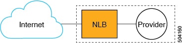
Note that the service graph could be a single-node service graph, where only the Network Load Balancer (NLB) is configured as a node in the service graph, as shown in the following graphic.
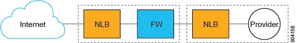
Or it could be a multi-node service graph, where additional service devices are also included in the service graph, such as a firewall or additional load balancers, as shown in the following graphic.
-
Creating one or more listeners in the EPG communication when a service graph is associated with a contract.
Listeners enable you to specify the ports and protocols (TCP or UDP) that the Network Load Balancer accepts and forwards traffic on. All listeners require you to configure at least one rule (a default rule, which does not have a condition). Rules enable you to specify the action that the Network Load Balancer takes when a condition is met; however, for Network Load Balancers, a rule can only forward traffic to a specific port of the backend pool.
The Network Load Balancer should be in a separate subnet, which should not be used to deploy other applications. There are two modes of operation in the Network Load Balancer:
-
Forward mode: Traffic is forwarded from a specific listener port to the specified backend port.
-
HA Port mode: The Network Load Balancer will load balance TCP and UDP flows on all the ports simultaneously.
Cisco Cloud APIC supports a Standard SKU Network Load Balancer only.
For more information, see the following:
-
The "About Network Load Balancer" section in the "Deploying Layer 4 to Layer 7 Services" chapter in the Cisco Cloud APIC for Azure User Guide
About Multiple Frontend IP Addresses on the Azure Network Load Balancer
When configuring an internet-facing Network Load Balancer, the number of public IP addresses allowed to assign to frontend the internet traffic varies, depending on the release:
-
Prior to Cisco Cloud APIC release 25.0(3) and Nexus Dashboard Orchestrator release 3.7(1), an internet-facing Network Load Balancer has a single public IP address assigned to frontend the internet traffic. The following graphic shows an example of a multi-node service graph configuration, where an internet-facing Network Load Balancer is shown at the top of the graphic, followed by VMs or a firewall, then an internal-facing Network Load Balancer as parts of this multi-node service graph.
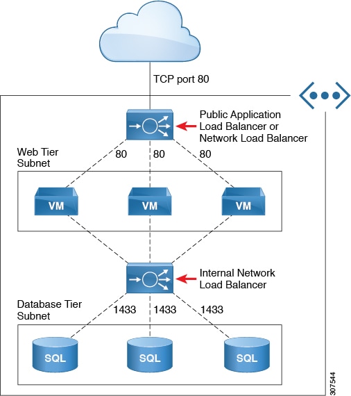
In this example, the internet-facing Network Load Balancer has a single public IP address assigned to frontend the internet traffic.
However, with this configuration, an issue might arise if you have a service graph and you need to expose multiple HTTPS services. Having the restriction of a single public IP address assigned to frontend the internet traffic for an internet-facing Network Load Balancer means that you cannot add more frontend IP addresses to that Network Load Balancer. In addition, you cannot add more Network Load Balancer in this situation due to a restriction from Azure, which does not allow multiple Network Load Balancers to share the same backend device (the firewalls in this example).
-
Beginning with Cisco Cloud APIC release 25.0(3) and Nexus Dashboard Orchestrator release 3.7(1), support is now available for configuring multiple frontend IP addresses for an internet-facing Network Load Balancer. With this update, each frontend IP address is attached to one or more rules to a specific backend pool.
The following graphic provides an example configuration where multiple frontend IP addresses are configured for an internet-facing Network Load Balancer.
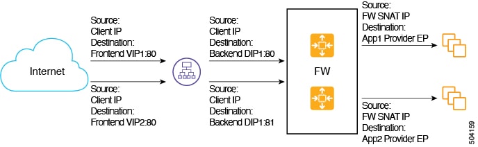
This example configuration depicts the packet flow for the following listener rules:
|
Listener Rule (Frontend Configuration) |
Rule Action (Backend Configuration) |
|
|---|---|---|
|
Rule1 |
|
Port: 80 |
|
Rule2 |
|
Port: 81 |
The service graph allows you to configure the settings for the listener rule and the rule action on services devices. When defined on a Network Load Balancer, the listener rule and rule action settings construct a mapping from a frontend configuration of the load balancer to a backend pool. Prior to Cisco Cloud APIC release 25.0(3) and Nexus Dashboard Orchestrator release 3.7(1), an internet-facing Network Load Balancer provided the ability to configure listeners with a single frontend IP address but with different port and protocol combinations. Beginning with Cisco Cloud APIC release 25.0(3) and Nexus Dashboard Orchestrator release 3.7(1), with the support for configuring multiple frontend IP addresses for an internet-facing Network Load Balancer, that ability is extended to configure listener rules with multiple frontends where each frontend is represented as a tuple combination of frontend IP addresses, port, and protocol.
Guidelines and Limitations
Following are the guidelines and limitations with the support for configuring multiple frontend IP addresses for an internet-facing Network Load Balancer:
-
Support for multiple frontend IP addresses is available only for an internet-facing Network Load Balancer.
-
Backend port reuse across multiple listener rules is not supported.
Deploying a Service Graph
The service graph enables you to define how traffic flows between devices, how the traffic comes into the network, which devices the traffic passes through, and how the traffic leaves the network.
The service graph can be deployed in two ways:
-
Single-node service graph: Only one device is deployed.
-
Multi-node service graph: Up to three nodes can be added to the service chain.
Before you can deploy a service graph in either a single-node or multi-node configuration, you must configure the following:
-
A tenant
-
An application profile
-
A consumer EPG
-
A provider EPG
-
A VRF
-
A cloud context profile
-
A contract with a filter
Configuring Multiple Frontend IP Addresses on Azure Network Load Balancer for Cisco Cloud APIC
In order to configure multiple frontend IP addresses on the Azure Network Load Balancer for Nexus Dashboard Orchestrator, you must first configure the service device in the Cisco Cloud APIC.
Creating Service Devices Using the Cloud APIC GUI
Before you begin
This section explains how to create service devices that can be used in a service graph through the Cisco Cloud APIC GUI.
Procedure
| Step 1 |
Click the Intent icon. The Intent menu appears. |
||||||||||||||||||||||||||||
| Step 2 |
Click the drop-down arrow below the Intent search box and choose Application Management. A list of Application Management options appear in the Intent menu. |
||||||||||||||||||||||||||||
| Step 3 |
From the Application Management list in the Intent menu, click . The Create Device dialog box appears. |
||||||||||||||||||||||||||||
| Step 4 |
Enter the necessary information for a Network Load Balancer:
|
||||||||||||||||||||||||||||
| Step 5 |
Click Save when finished. The Create Service Graph dialog box appears. To see the frontend IP addresses associated with the default and configured frontend IP names: |
||||||||||||||||||||||||||||
Configuring Multiple Frontend IP Addresses on Azure Network Load Balancer for Nexus Dashboard Orchestrator
The following topics describe how to configure multiple frontend IP addresses on the Azure Network Load Balancer for Nexus Dashboard Orchestrator.
Understanding How Nexus Dashboard Orchestrator Implements the Multiple Frontend IP Address Feature
The multiple front-end IP address feature is supported in Cisco Nexus Dashboard Orchestrator release 3.7(1). In order to implement this feature as decribed in Understanding Configurations for Multiple Frontend IP Addresses on the Azure Network Load Balancer for Nexus Dashboard Orchestrator, you must first configure the internet-facing Azure Network Load Balancer service device in Cisco Cloud APIC. Nexus Dashboard Orchestrator will then pull the configuration that you did when you configured the internet-facing Azure Network Load Balancer service device in Cisco Cloud APIC. Then, you will configure the service graph and listeners in Nexus Dashboard Orchestrator using the service device that you configured in Cisco Cloud APIC.
 Note |
This feature will only work in Cisco Nexus Dashboard Orchestrator 3.7(1) with Azure Cloud APIC version 25.0.3 or higher. |
For more information, see Understanding Configurations for Multiple Frontend IP Addresses on the Azure Network Load Balancer
Creating a Service Graph Template
Before you begin
You should have configured the internet-facing Azure Network Load Balancer service device to implement the new multiple front-end IP addresses feature in Cloud APIC using the instructions in Creating Service Devices Using the Cloud APIC GUI.
Procedure
| Step 1 |
Navigate to Nexus Dashboard Orchestrator. |
| Step 2 |
Under Application Management, choose Schema. |
| Step 3 |
Select the Schema where you want to expose multiple front-end IP addresses on the Network Load Balancer. |
| Step 4 |
Under Template, select your template. |
| Step 5 |
Create service graph, and under common properties, fill-in service graph template Display Name then choose and drag Load Balaner icon from Services Nodes menu to build graph. |
| Step 6 |
Select the template, under Sites. |
| Step 7 |
Choose the Service Graph, and under Template properties select Load Balancer. |
| Step 8 |
From the pop-up window, under device select your Network Load Balancer and click Done. This is the Network Load Balancer service device that you configured in Cisco Cloud APIC that you are pulling into Nexus Dashboard Orchestrator. |
Deploying Layer 4 to Layer 7 Services
Procedure
| Step 1 |
Navigate to the Schema and select your template. |
| Step 2 |
Under Contracts, select the contract. In the template level properties, choose the service graph that contains the internet-facing Network Load Balancer that you configured in the previous section. |
| Step 3 |
Once you have attached the contract to the service graph, go to the local site-level template properties and choose the same contract to configure the Listener. |
| Step 4 |
Click the internet-facing Network Load Balancer. |
| Step 5 |
From the pop-up window, choose Add Listener. |
| Step 6 |
Determine which Front-end IP address you will use to configure load balancer listener.
|
| Step 7 |
Scroll down and choose Add rule for the changes you made. |
| Step 8 |
In the Upper right corner, click on the Check mark icon to implement the changes. |
| Step 9 |
Select Save to save the Listener. |
| Step 10 |
Repeat these steps to configure additional cloud load balancer listeners for additional front-end IP addresses. |
Trademarks
THE SPECIFICATIONS AND INFORMATION REGARDING THE PRODUCTS REFERENCED IN THIS DOCUMENTATION ARE SUBJECT TO CHANGE WITHOUT NOTICE. EXCEPT AS MAY OTHERWISE BE AGREED BY CISCO IN WRITING, ALL STATEMENTS, INFORMATION, AND RECOMMENDATIONS IN THIS DOCUMENTATION ARE PRESENTED WITHOUT WARRANTY OF ANY KIND, EXPRESS OR IMPLIED.
The Cisco End User License Agreement and any supplemental license terms govern your use of any Cisco software, including this product documentation, and are located at: http://www.cisco.com/go/softwareterms.Cisco product warranty information is available at http://www.cisco.com/go/warranty. US Federal Communications Commission Notices are found here http://www.cisco.com/c/en/us/products/us-fcc-notice.html.
IN NO EVENT SHALL CISCO OR ITS SUPPLIERS BE LIABLE FOR ANY INDIRECT, SPECIAL, CONSEQUENTIAL, OR INCIDENTAL DAMAGES, INCLUDING, WITHOUT LIMITATION, LOST PROFITS OR LOSS OR DAMAGE TO DATA ARISING OUT OF THE USE OR INABILITY TO USE THIS MANUAL, EVEN IF CISCO OR ITS SUPPLIERS HAVE BEEN ADVISED OF THE POSSIBILITY OF SUCH DAMAGES.
Any products and features described herein as in development or available at a future date remain in varying stages of development and will be offered on a when-and if-available basis. Any such product or feature roadmaps are subject to change at the sole discretion of Cisco and Cisco will have no liability for delay in the delivery or failure to deliver any products or feature roadmap items that may be set forth in this document.
Any Internet Protocol (IP) addresses and phone numbers used in this document are not intended to be actual addresses and phone numbers. Any examples, command display output, network topology diagrams, and other figures included in the document are shown for illustrative purposes only. Any use of actual IP addresses or phone numbers in illustrative content is unintentional and coincidental.
The documentation set for this product strives to use bias-free language. For the purposes of this documentation set, bias-free is defined as language that does not imply discrimination based on age, disability, gender, racial identity, ethnic identity, sexual orientation, socioeconomic status, and intersectionality. Exceptions may be present in the documentation due to language that is hardcoded in the user interfaces of the product software, language used based on RFP documentation, or language that is used by a referenced third-party product.
Cisco and the Cisco logo are trademarks or registered trademarks of Cisco and/or its affiliates in the U.S. and other countries. To view a list of Cisco trademarks, go to this URL: www.cisco.com go trademarks. Third-party trademarks mentioned are the property of their respective owners. The use of the word partner does not imply a partnership relationship between Cisco and any other company. (1721R)
 Feedback