Cisco Service Control Value Added Services Solution Guide, Release 3.6.x
Bias-Free Language
The documentation set for this product strives to use bias-free language. For the purposes of this documentation set, bias-free is defined as language that does not imply discrimination based on age, disability, gender, racial identity, ethnic identity, sexual orientation, socioeconomic status, and intersectionality. Exceptions may be present in the documentation due to language that is hardcoded in the user interfaces of the product software, language used based on RFP documentation, or language that is used by a referenced third-party product. Learn more about how Cisco is using Inclusive Language.
- Updated:
- January 25, 2011
Chapter: Overview of the Value Added Services Feature
Overview of the Value Added Services Feature
Introduction
The VAS feature uses the SCE platform to access an external "expert system" for classification and control of services not supported by SCA BB. Using the VAS feature, you can forward selected flows to an external, third-party system for per-subscriber processing in addition to the existing services and functions of the SCA BB solution. For example, this feature can be used to forward selected subscriber traffic to third-party servers for intrusion detection or content-filtering.
The VAS feature enables you to divert a specified part of the traffic stream to an individual VAS server or a cluster of servers. The diversion of the traffic stream is based on the subscriber package, flow type, and the availability of the VAS servers. The feature provides load balancing for even distribution of the load on the various VAS servers.
The VAS feature supports multiple VAS service types using different VAS server groups. Several servers of the same type can be deployed in a group to increase the processing capacity and provide redundancy for each VAS service type.
The SCE platform performs subscriber load sharing between the active servers of the same server group. It is able to identify the active servers among the defined servers through a dedicated health check mechanism.
VAS Service Goals
The VAS traffic forwarding functionality enables the Service Control solution to meet several important service goals:
•![]() Service providers can provide a range of value-added services to their subscribers, thus increasing customer satisfaction.
Service providers can provide a range of value-added services to their subscribers, thus increasing customer satisfaction.
•![]() The SCE platform can forward part of the traffic to third-party devices that can provide additional, complementary services.
The SCE platform can forward part of the traffic to third-party devices that can provide additional, complementary services.
The SCE platform, due to its strong classification capabilities, forwards only the part of the traffic that should get the additional service based on:
–![]() Subscriber awareness
Subscriber awareness
–![]() Policy that was configured
Policy that was configured
•![]() The Service Control solution can include value-added servers that cannot be deployed inline for various reasons (for example, they cannot support throughput or are not carrier grade for inline insertion).
The Service Control solution can include value-added servers that cannot be deployed inline for various reasons (for example, they cannot support throughput or are not carrier grade for inline insertion).
•![]() Easy interoperability and flexibility for setting different services.
Easy interoperability and flexibility for setting different services.
Because the VAS feature emulates a regular IP network for the third-party devices, no special support is required on the part of the third-party entity.
How VAS Traffic Forwarding Works
Subscribers are provisioned to the VAS services as part of the normal provisioning process of new subscribers to SCA BB.
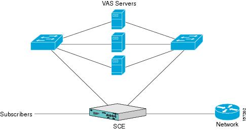
When VAS traffic forwarding is enabled (Figure 1-1), in addition to all its basic functions, the SCA BB application classifies each flow as either a VAS flow or as a standard flow (non-VAS flow).
Flows that are classified to a VAS service get the usual SCA BB service in addition to being forwarded to the VAS servers for additional service. Traffic is processed first by the SCA BB application and then forwarded to the VAS servers.
Traffic is routed to the VAS servers using VLAN tags to identify the traffic flows.
Figure 1-1 Typical VAS Traffic Forwarding Installation
VAS traffic forwarding guidelines:
•![]() Maximum number of VAS servers per single SCE platform:
Maximum number of VAS servers per single SCE platform:
–![]() SCE 2000—8
SCE 2000—8
–![]() SCE8000—64
SCE8000—64
•![]() Maximum number of SCE platforms that can be connected:
Maximum number of SCE platforms that can be connected:
–![]() SCE 2000—512
SCE 2000—512
–![]() SCE8000—64
SCE8000—64
•![]() Maximum number of VAS server groups—Eight (applies to both SCE8000 and SCE 2000 platforms).
Maximum number of VAS server groups—Eight (applies to both SCE8000 and SCE 2000 platforms).
•![]() The same VAS server may be used by more than one SCE platform.
The same VAS server may be used by more than one SCE platform.
•![]() The VAS traffic forwarding feature is not supported on the SCE 1000 2xGBE platform.
The VAS traffic forwarding feature is not supported on the SCE 1000 2xGBE platform.

Note ![]() In VAS mode, the SCE performance envelope might be up to 50 percent lower than in the normal operation mode. The exact performance envelope is specific to the traffic mix in the customer network and should be sized in advance.
In VAS mode, the SCE performance envelope might be up to 50 percent lower than in the normal operation mode. The exact performance envelope is specific to the traffic mix in the customer network and should be sized in advance.
The following sections provide a more detailed description of how VAS traffic forwarding works
•![]() .Requirements for VAS Servers
.Requirements for VAS Servers
•![]() VAS Traffic Forwarding and SCA BB
VAS Traffic Forwarding and SCA BB
•![]() VLAN Tags for VAS Traffic Forwarding
VLAN Tags for VAS Traffic Forwarding
.Requirements for VAS Servers
Because the VAS devices are installed behind the SCE platform, they should follow the network behavior of the SCE platform. Therefore, VAS devices must meet the following two requirements:
•![]() VAS devices must be equipped with two separate interfaces, one for the subscriber side and and one for the network side.
VAS devices must be equipped with two separate interfaces, one for the subscriber side and and one for the network side.
Traffic toward the subscribers should be sent from the subscriber interface and for the Internet from the network interface.
•![]() VAS devices must be transparent in Layer 2. The VAS servers must act like Layer 2 switches in that they are not allowed to change traffic headers or to generate new traffic.
VAS devices must be transparent in Layer 2. The VAS servers must act like Layer 2 switches in that they are not allowed to change traffic headers or to generate new traffic.
Layer 2 Transparency
To handle non-management traffic of VAS services, follow these guidelines:
•![]() The VAS services should work in promiscuous-mode in Layer 2 and accept packets with any destination MAC address.
The VAS services should work in promiscuous-mode in Layer 2 and accept packets with any destination MAC address.
•![]() When forwarding traffic back to the network after processing, the VAS devices must preserve the original Layer 2 headers containing the MAC addresses and the VLAN tag. The VAS devices must not change the MAC addresses (destination or source) or the VLAN tags. The following restrictions apply to the injected traffic:
When forwarding traffic back to the network after processing, the VAS devices must preserve the original Layer 2 headers containing the MAC addresses and the VLAN tag. The VAS devices must not change the MAC addresses (destination or source) or the VLAN tags. The following restrictions apply to the injected traffic:
–![]() The VAS device is not permitted to initiate new flows.
The VAS device is not permitted to initiate new flows.
–![]() New traffic can be injected only in the context of an existing flow.
New traffic can be injected only in the context of an existing flow.
–![]() When injecting traffic, the Layer 2 information (MAC addresses, VLAN tags, and the TCP/IP parameters) must be taken from the flow into which the traffic is being injected.
When injecting traffic, the Layer 2 information (MAC addresses, VLAN tags, and the TCP/IP parameters) must be taken from the flow into which the traffic is being injected.
•![]() A VAS device must not generate its own network transactions or relay such transactions. Network transactions such as ARP requests or pings are not permitted.
A VAS device must not generate its own network transactions or relay such transactions. Network transactions such as ARP requests or pings are not permitted.
VAS Management Traffic
VAS devices that are managed inband (through the traffic interface) must meet the following requirements:
•![]() Management traffic should either be carried over a dedicated VLAN or without any VLAN header.
Management traffic should either be carried over a dedicated VLAN or without any VLAN header.
•![]() The switches that are connected to the VAS devices should be directly connected to the POP router.
The switches that are connected to the VAS devices should be directly connected to the POP router.
•![]() The switches that are connected to the VAS devices should be configured so that management traffic is sent directly to the router and not through the SCE platform.
The switches that are connected to the VAS devices should be configured so that management traffic is sent directly to the router and not through the SCE platform.
VAS Traffic Forwarding and SCA BB
When VAS traffic forwarding is enabled, in addition to all its basic functions, the SCA BB application classifies each flow as either a VAS flow or as a standard flow (non-VAS flow). This classification is made on the first packet of the flow (for example, TCP SYN packet). The classification must be performed on the very first packet because the classification is used to select the routing of the packet to a VAS server or to the subscriber or network.
The VAS traffic forwarding rules table is configured using the SCA BB console. These rules map certain traffic to the VAS server groups. When a flow is classified as a VAS flow, the VAS server group for this flow is selected. If the group includes more than one VAS server, traffic is forwarded so that the subscriber load is shared between the servers on the same group.
The mapping of traffic portions per package to VAS server groups is also done using the SCA BB console.
VLAN Tags for VAS Traffic Forwarding
The traffic is routed between the SCE platform and the VAS servers by VLANs. There is a unique VLAN tag for each SCE platform and VAS server combination.
Before the traffic is forwarded to the VAS servers, the SCE platform adds the VLAN tags to the original traffic. When the traffic returns to the SCE platform, the SCE platform removes the VLAN tag it previously added, and then forwards the traffic on its original link.
The VLAN tag for each VAS server is user-configured. To preserve consistency of the traffic flow, the VAS feature requires a unique VLAN tag be configured for each SCE platform and VAS server combination.
The VLAN tag has 12 bits, divided as follows:
•![]() SCE8000 (maximum of 64 VAS servers):
SCE8000 (maximum of 64 VAS servers):
–![]() The lower six bits identify the VAS server.
The lower six bits identify the VAS server.
–![]() The higher six bits identify the SCE platform.
The higher six bits identify the SCE platform.
For example, 0x171 = 1011 10001 = SCE 11, VAS 17
•![]() SCE 2000 (maximum of eight VAS servers):
SCE 2000 (maximum of eight VAS servers):
–![]() The lower three bits identify the VAS server.
The lower three bits identify the VAS server.
–![]() The higher nine bits identify the SCE platform.
The higher nine bits identify the SCE platform.
For example, 0x20 = 100 000 = SCE 4, VAS 0
Observe the following for the higher bits that identify the SCE platform:
•![]() The higher bits must be the same for all VAS servers attached to a specific SCE platform.
The higher bits must be the same for all VAS servers attached to a specific SCE platform.
•![]() These bits must be different for VAS servers attached to different SCE platforms.
These bits must be different for VAS servers attached to different SCE platforms.
The SCE platform enforces that the user-configured VLAN tags retain this format, that is, the lower bits match the VAS server number for which the VLAN tag is configured and the higher bits match the higher bits previously configured for other VAS servers on this SCE platform. However, the SCE platform cannot determine the configuration of other SCE platforms, and therefore, it is important that the configured SCE ID (higher bits) be unique for each SCE platform.
The use of VLAN tags is an integral part of the VAS feature, and therefore, requires that the VAS device be able to work in 802.1q trunk while preserving the VLAN information.
Service Flow
The SCE platform classifies a flow to a VAS server group based on the subscriber package and the TCP/UDP ports of the flow. It then selects one server within this group to handle the flow.
The SCE platform performs load sharing between multiple VAS servers belonging to the same server group; the balance is based on the subscriber load. In other words, the SCE platform ensures that the subscribers are evenly distributed between the VAS servers in the same group.The mapping of subscriber to a VAS server (per group) is maintained even when servers are added or removed from the group either due to configuration changes or changes in the operational status of the servers in the group. The mapping changes only if the same server changes its status.
The following sections explain in more detail when and how the mapping is changed.
Data Flow
In a deployment using VAS traffic forwarding, there are two types of data flows:
•![]() Non-VAS flow
Non-VAS flow
•![]() VAS flow
VAS flow
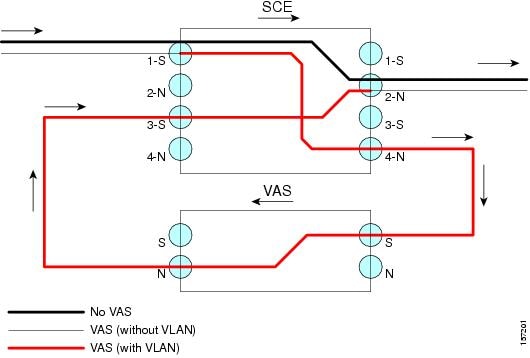
Figure 1-2 depicts the two types of data flows running through a single SCE platform and a single VAS server.
•![]() Ports are illustrated as two unidirectional half ports, RX (on the left side) and TX (on the right side):
Ports are illustrated as two unidirectional half ports, RX (on the left side) and TX (on the right side):
–![]() The SCE platform has four ports.
The SCE platform has four ports.
–![]() The VAS server has two ports.
The VAS server has two ports.
•![]() For the sake of illustration, the SCE platform traffic flow direction is from left to right while the VAS traffic flow is from right to left. The arrow below the name of the element indicates the traffic flow direction.
For the sake of illustration, the SCE platform traffic flow direction is from left to right while the VAS traffic flow is from right to left. The arrow below the name of the element indicates the traffic flow direction.
•![]() The Ethernet switches are omitted.
The Ethernet switches are omitted.
•![]() Each line represents a flow:
Each line represents a flow:
–![]() Thick line is a non-VAS flow.
Thick line is a non-VAS flow.
–![]() Thin line is a VAS flow.
Thin line is a VAS flow.
–![]() Black line indicates part of a flow that does not have a VLAN tag.
Black line indicates part of a flow that does not have a VLAN tag.
–![]() Red line indicates part of a flow that has a VLAN tag.
Red line indicates part of a flow that has a VLAN tag.
Figure 1-2 illustrates the data flow from the subscriber to the network. Data flow from the network to the subscriber works in the same way, but is received on the network port (N) and transmitted on the subscriber port (S).
Figure 1-2 Data Flow in a VAS System
Non-VAS Data Flow
The data flow steps for a non-VAS flow are:
1. ![]() A subscriber packet is received at the SCE platform Port 1 (S).
A subscriber packet is received at the SCE platform Port 1 (S).
2. ![]() The SCE platform classifies the flow as non-VAS flow.
The SCE platform classifies the flow as non-VAS flow.
3. ![]() The packet is sent to the network on Port 2 (N).
The packet is sent to the network on Port 2 (N).
VAS Data Flow
A VAS data flow is slightly more complex than the basic data flow. It is received and transmitted in the same manner as the basic non-VAS SCE platform flow, but before it is transmitted to its original destination, it flows through the VAS server.
The data flow steps for a VAS flow are:
1. ![]() A subscriber packet is received at the SCE platform Port 1 (S).
A subscriber packet is received at the SCE platform Port 1 (S).
2. ![]() The SCE platform classifies the flow as a VAS flow.
The SCE platform classifies the flow as a VAS flow.
3. ![]() The SCE platform adds a VLAN tag to the packet.
The SCE platform adds a VLAN tag to the packet.
4. ![]() The VLAN tag is used by the Ethernet switch to route the packet to the proper VAS server.
The VLAN tag is used by the Ethernet switch to route the packet to the proper VAS server.
The packet now has a VLAN tag, which is indicated by the red line.
5. ![]() The packet is sent to the VAS subscriber port from SCE platform Port 4 (N).
The packet is sent to the VAS subscriber port from SCE platform Port 4 (N).
6. ![]() The VAS server processes the packets and either drops the packet or sends it back to the SCE platform from the VAS network port to the SCE platform subscribers Port 3 (S).
The VAS server processes the packets and either drops the packet or sends it back to the SCE platform from the VAS network port to the SCE platform subscribers Port 3 (S).
The VAS server passes the VLAN tag transparently. This is important to enable the Ethernet switch (not shown) to route the packet back to the proper SCE platform.
7. ![]() The SCE platform receives the packet on Port 3 (S), drops the VLAN tag, and passes the packet towards the network through Port 2 (N).
The SCE platform receives the packet on Port 3 (S), drops the VLAN tag, and passes the packet towards the network through Port 2 (N).
Load Balancing
VAS servers can be grouped logically according to their service type. Consider, for example, a system that requires both FTP caching and virus filtering. A single VAS server for each service might not have enough capacity. For example, assume that the system requires five VAS servers, three to provide FTP caching, and two to provide virus filtering. Defining two VAS server groups, for example, FTP caching and virus filtering, permits load sharing across the servers for each server group.
The subscriber package determines the VAS server group to which the flow should be attached. The selection of a specific VAS server from the VAS servers within the group is based on the current load on each VAS server. The system tries to create an equal subscriber load for all the VAS servers belonging to the same group.
In some cases, a single VAS server may be used by more than one SCE platform. Remember that the SCE platform performs load balancing only on the traffic that it sends to the VAS server; it receives no information regarding the load the VAS server may be bearing from a different SCE platform. It is vital to properly allocate available VAS servers to the SCE platforms to ensure a balanced load on each VAS server.
Load Balancing and Subscribers
The system balances the usage of the VAS servers within a VAS server group, trying to create an equal subscriber load for all the VAS servers in one VAS server group. The load balancing is subscriber based, that is, the subscribers are evenly distributed between the servers.
VAS load sharing is subscriber based rather than bandwidth based to ensure that all the traffic of the subscriber gets to the same server so that the server can make subscriber-based decisions.
The SCE platform uses the same VAS server for all the traffic of a subscriber (per server group) even if there is a change in the number of active servers in the group. Traffic from a subscriber is assigned to a new server only if the current server becomes inactive. This applies only on new flows. Flows that were already mapped to a server before it became active remain attached to it.
The mapping of subscriber to VAS servers is not saved across subscriber logouts or SCE platform reload.
Load Balancing and Subscriber Mode
Load balancing is subscriber based, therefore this feature does not work properly in subscriberless mode, because the entire traffic load would be carried by only one VAS server per group.

Tip ![]() Use anonymous mode rather than subscriberless mode with VAS traffic forwarding.
Use anonymous mode rather than subscriberless mode with VAS traffic forwarding.
In pull mode, the first flow of the subscriber behaves as configured in the anonymous template. If no anonymous template is configured, such first flows are processed as defined by the default template. Therefore, the default template should provide a proper package, so these flows get VAS service.
VAS Redundancy
The VAS servers should be configured with high availability so that the failure of a single VAS server will not degrade total system performance and availability. This requirement must be considered when determining the number of VAS servers necessary for each VAS service.
There are two mechanisms that guarantee the performance and availability of the VAS services:
•![]() Load sharing—The SCE platform distributes the subscribers between all the active VAS servers within a server group.
Load sharing—The SCE platform distributes the subscribers between all the active VAS servers within a server group.
•![]() Monitoring—The SCE platform monitors connectivity with the VAS servers and handles server failure according to the applied configuration.
Monitoring—The SCE platform monitors connectivity with the VAS servers and handles server failure according to the applied configuration.
In addition to failure of an individual VAS server, a complete VAS server group is considered to be failed if a defined minimum number of servers are not active.
The following sections provide more information regarding the possible points of failure in a VAS traffic forwarding deployment.
VAS Server Failure
The system monitors the health of a VAS server by periodically checking the connectivity between the SCE platform and the VAS server. When the SCE platform fails to establish or maintain a connection to the server within a configurable window of time, the server is considered to be in Down state.
When the server is in Down state:
•![]() New logged-in subscribers are distributed between the other active servers in the group.
New logged-in subscribers are distributed between the other active servers in the group.
•![]() Subscribers that are mapped to this server are mapped to a new server if they initiate a new flow.
Subscribers that are mapped to this server are mapped to a new server if they initiate a new flow.
•![]() The server group may move to a Failure state if the failure caused the number of active servers in the group to go below the minimum number configured.
The server group may move to a Failure state if the failure caused the number of active servers in the group to go below the minimum number configured.
If the connectivity to the server resumes, the state of the server is changed to Up. The server returns to the list of active servers and continues to serve subscribers that were mapped to it before the failure and have not yet been mapped to a new server during the failure time, as well as new subscribers.
VAS Server Group Failure
For each VAS server group, you can configure:
•![]() The minimum number of active servers necessary.
The minimum number of active servers necessary.
•![]() The action to take in case the actual number of active servers goes below the configured minimum.
The action to take in case the actual number of active servers goes below the configured minimum.
If the minimum number of active servers equals the total number of configured servers, it means there is no redundancy and failure of one server causes the failure of the whole server group.
When the SCE platform detects that the number of active servers within a group is below the configured minimum, it changes the state of the group to Failure. The configured action-on-failure is then applied to all new flows mapped for that VAS server group (existing flows are not affected.)
There are two possible actions when the VAS server group has failed:
•![]() Block—All new flows assigned to the failed VAS server group are blocked by the SCE platform.
Block—All new flows assigned to the failed VAS server group are blocked by the SCE platform.
•![]() Pass—All new flows assigned to the failed VAS server group are considered as regular non-VAS flows, and are processed without VAS service (that is, they receive SCA BB service but not VAS service).
Pass—All new flows assigned to the failed VAS server group are considered as regular non-VAS flows, and are processed without VAS service (that is, they receive SCA BB service but not VAS service).
When the number of active servers is above the minimum and the state of the group is changed to Active again, the configured action-on-failure is no longer applied to the new flows. However, to maintain the coherency of the network, flows that were blocked or passed are not affected by the change in the state of the server group.
Ethernet Switch Failure
The Ethernet switches are a single point of failure in a VAS topology. A complete failure of an Ethernet switch causes all the VAS services to be declared as failed and the configured action (on-failure) is taken for all new VAS flows.
Disabling a VAS Server
A VAS server can be disabled for maintenance via the CLI.
No errors are reported on a disabled VAS server. However, if disabling the server reduces the number of active servers to below the minimum number configured for the group, it brings down the VAS server group because a disabled VAS server is equal to a VAS server in Down state.
Health check is not performed on disabled VAS servers.
VAS Status and VAS Health Check
To manage the VAS redundancy, the SCE platform needs to know the state of each VAS server. The SCE platform performs periodic health checks for all the configured VAS servers. These checks are the basis for VAS redundancy control; they enable the SCE platform to identify and react to VAS server failure, and to check the connectivity between the SCE platform and the VAS server before enabling the server to handle traffic.
The health check is performed over the VAS link, that is, the link that connects the SCE platform with the VAS servers. It validates the traffic flow between the SCE platform and the VAS server in both directions through special health check packets generated by the SCE platform.
The health check mechanism does not require special interaction with the VAS device. This is because the VAS server does not have to answer health check packets; it only passes them as they are, back to the SCE platform. As long as the packets are received by the SCE platform, the VAS server is considered to be alive. Failing to receive the packets back from the VAS server within a predefined time window is considered by the SCE platform as a failure of the VAS server and the server status is changed to Down.
Health check packets are:
•![]() Carried over UDP flows.
Carried over UDP flows.
•![]() Contain source and destination IP addresses that can be user-configured.
Contain source and destination IP addresses that can be user-configured.
IP addresses should be:
–![]() Unique to the SCE platform.
Unique to the SCE platform.
–![]() Addresses that are not used by the network traffic (such as private IPs).
Addresses that are not used by the network traffic (such as private IPs).
The SCE platform uses default UDP ports beginning with 63140 and 63141 for VAS Server 0, unless you configure different ports for the health check.
The SCE platform adds its own Layer 7 data on top of the UDP transport layer. This data is used by the SCE platform to validate the correctness of the packet upon retrieval.
The health check is performed under the following conditions:
•![]() VAS mode is enabled.
VAS mode is enabled.
•![]() VAS server is enabled.
VAS server is enabled.
•![]() Health check for the VAS server is enabled.
Health check for the VAS server is enabled.
•![]() Server has a VLAN tag.
Server has a VLAN tag.
•![]() Pseudo IPs are configured for the traffic interfaces.
Pseudo IPs are configured for the traffic interfaces.
If the check is enabled, but any one of the conditions is not met, the server state will be Down (the same as if the server did not pass the health check).
Check the connectivity between the SCE platform and the VAS server before you assign the server to a server group.
The health check procedure does not require a special interface with the VAS server; the health check traffic goes through the same network channels as any other VAS traffic. However, there are two assumptions the VAS servers should fulfill:
•![]() The VAS server should not drop traffic unless it is specifically configured to do so. Therefore, if the connectivity between the VAS server and the SCE platform is operative, the health check packets should reach the SCE platform safely.
The VAS server should not drop traffic unless it is specifically configured to do so. Therefore, if the connectivity between the VAS server and the SCE platform is operative, the health check packets should reach the SCE platform safely.
Alternatively, it should be possible to configure the VAS server to pass traffic on specific ports (the health check ports).
•![]() In case of a failure, the VAS server should drop and not bypass, the traffic (cut the link), so that the SCE platform is able to identify the failure.
In case of a failure, the VAS server should drop and not bypass, the traffic (cut the link), so that the SCE platform is able to identify the failure.
VAS Server States
When determining whether a VAS server is active, the system considers the following two parameters:
•![]() User-configured Admin mode—Enabled or disabled
User-configured Admin mode—Enabled or disabled
•![]() VAS server state as reported by the health check
VAS server state as reported by the health check
VAS Traffic Forwarding Topologies
The following sections describe the following VAS traffic forwarding topologies:
•![]() Single SCE Platform, Multiple VAS Servers
Single SCE Platform, Multiple VAS Servers
•![]() Multiple SCE Platforms, Multiple VAS Servers
Multiple SCE Platforms, Multiple VAS Servers
Note ![]() A topology in which a VAS server is directly connected to the SCE platform is not supported. If you want a topology of a single SCE platform connected to a single VAS server, use a switch between the SCE platform and the VAS server.
A topology in which a VAS server is directly connected to the SCE platform is not supported. If you want a topology of a single SCE platform connected to a single VAS server, use a switch between the SCE platform and the VAS server.
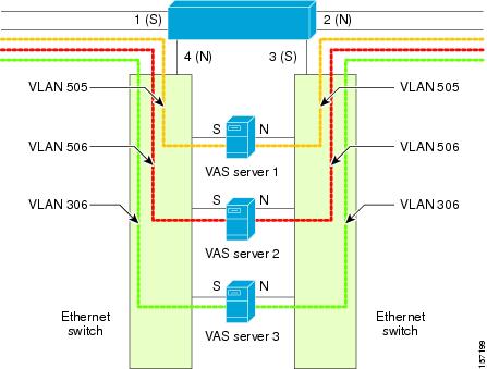
Single SCE Platform, Multiple VAS Servers
In this topology, a single SCE platform forwards VAS traffic to one or more VAS servers through two Ethernet switches (Figure 1-3).
The two Ethernet switches are necessary to avoid a situation in which a single MAC address has two ports or a single VLAN tag has two destinations. Each Ethernet switch should be configured to trunk mode with MAC learning disabled.
Figure 1-3 Single SCE Platform, Multiple VAS Servers
Data Flow
In a data flow:
1. ![]() A subscriber packet is received at Port #1 (Subscriber).
A subscriber packet is received at Port #1 (Subscriber).
2. ![]() The SCE platform opens a flow and classifies the flow as either a non-VAS (blue) flow or as a VAS flow (red).
The SCE platform opens a flow and classifies the flow as either a non-VAS (blue) flow or as a VAS flow (red).
3. ![]() If the flow is non-VAS (blue), the SCE platform passes the packet to the network. The VAS server is not involved in this case.
If the flow is non-VAS (blue), the SCE platform passes the packet to the network. The VAS server is not involved in this case.
4. ![]() If the flow is a VAS flow (red), the SCE platform selects the VAS server to which the packet should be sent, adds the server VLAN tag to the packet, and transmits the packet on Port #4 (Network).
If the flow is a VAS flow (red), the SCE platform selects the VAS server to which the packet should be sent, adds the server VLAN tag to the packet, and transmits the packet on Port #4 (Network).
5. ![]() The packet is routed by the Ethernet switch to the VAS server according to its VLAN tag (the port towards the VAS server should be the only port with this VLAN tag allowed).
The packet is routed by the Ethernet switch to the VAS server according to its VLAN tag (the port towards the VAS server should be the only port with this VLAN tag allowed).
6. ![]() The VAS server processes the packet and either drops or forwards it without changing the VLAN tag.
The VAS server processes the packet and either drops or forwards it without changing the VLAN tag.
7. ![]() The packet is forwarded by the Ethernet switch to the SCE platform according to its VLAN tag (the port towards the SCE platform should be the only port with this VLAN tag allowed).
The packet is forwarded by the Ethernet switch to the SCE platform according to its VLAN tag (the port towards the SCE platform should be the only port with this VLAN tag allowed).
8. ![]() The SCE platform receives the packet on port #3 (Subscriber), strips the VLAN tag, and forwards the packet to the network via Port #2 (Network).
The SCE platform receives the packet on port #3 (Subscriber), strips the VLAN tag, and forwards the packet to the network via Port #2 (Network).
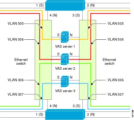
Multiple SCE Platforms, Multiple VAS Servers
In this topology, multiple SCE platforms are connected to multiple VAS servers. At least one VAS server receives traffic from more than one SCE platform; if the VAS servers are each in an exclusive relationship to a particular SCE platform, it would simply be several single SCE platform to multiple VAS server topologies grouped together.
In Figure 1-4, the top SCE platform forwards traffic to VAS Server 1 and Server 2, while the bottom SCE platform forwards to VAS Server 2 and Server 3. A unique VLAN tag must designate each SCE-platform-to-VAS-server path. This topology is illustrated with two SCE platforms, but a maximum of 64 SCE8000 platforms or 512 SCE 2000 platforms is supported (limited by the VLAN tag size).
The two Ethernet switches route the traffic to the VAS servers. The routing is VLAN based. The Ethernet switch should be configured to trunk mode with learning disabled.
The data flow is the same as that for the single SCE platform to multiple VAS servers topology (see Data Flow).
Note ![]() The multiple SCE platforms to multiple VAS servers topology does not support SCE platform redundancy on the cascade ports.
The multiple SCE platforms to multiple VAS servers topology does not support SCE platform redundancy on the cascade ports.
Figure 1-4 Multiple SCE Platforms, Multiple VAS Servers
SNMP Support for VAS
The following items in the "PCUBE-SE-MIB" proprietary MIB support VAS traffic forwarding:
•![]() SCE-MIB object—vasTrafficForwardingGrp SCE-MIB
SCE-MIB object—vasTrafficForwardingGrp SCE-MIB
•![]() Object type—vasServersTable provides information on each VAS server operational status.
Object type—vasServersTable provides information on each VAS server operational status.
•![]() SNMP Trap—vasServerOperationalStatusChangeTrap signifies that the agent entity has detected a change in the operational status of a VAS server.
SNMP Trap—vasServerOperationalStatusChangeTrap signifies that the agent entity has detected a change in the operational status of a VAS server.
Interactions Between VAS Traffic Forwarding and Other SCE Platform Features
•![]() Incompatible SCE Platform Features
Incompatible SCE Platform Features
•![]() VAS Traffic Forwarding and DDoS Processing
VAS Traffic Forwarding and DDoS Processing
•![]() VAS Traffic Forwarding and Bandwidth Management
VAS Traffic Forwarding and Bandwidth Management
Incompatible SCE Platform Features
There are certain SCE platform features that are incompatible with VAS traffic forwarding. Before you enable VAS traffic forwarding, you must ensure that no incompatible features or modes are configured.
The features and modes listed below cannot coexist with VAS mode:
•![]() Line-card connection modes—receive-only, receive-only-cascade, inline-cascade
Line-card connection modes—receive-only, receive-only-cascade, inline-cascade
•![]() Link mode other than forwarding
Link mode other than forwarding
•![]() All link encapsulation protocols, including VLAN, MPLS, and L2TP
All link encapsulation protocols, including VLAN, MPLS, and L2TP
•![]() Traffic mirroring
Traffic mirroring
VAS Traffic Forwarding and DDoS Processing
VAS traffic forwarding has minor effects on the distributed denial of service (DDoS) mechanisms.
•![]() Specific IP DDoS Attack Detection
Specific IP DDoS Attack Detection
Specific IP DDoS Attack Detection
The specific IP DDoS mechanism uses software counters. The second pass VAS packets do not reach the Service Control Operating System (SCOS), so they are not counted twice.
Network-side packets are handled by the attack-detector in the first pass, when they open a flow, so they are also not counted twice.
Specific IP Attack Filter
The behavior depends on the action configured.
•![]() Report only—VAS is not affected.
Report only—VAS is not affected.
•![]() Block—Flow is blocked, no VAS service is provided.
Block—Flow is blocked, no VAS service is provided.
•![]() Bypass—Traffic is bypassed and NO SCA BB or VAS services are provided.
Bypass—Traffic is bypassed and NO SCA BB or VAS services are provided.
VAS Traffic Forwarding and Bandwidth Management
The complexity of the VAS traffic forwarding results in the modification of some SCE platform bandwidth management capabilities:
•![]() VAS flows are not subject to global bandwidth control.
VAS flows are not subject to global bandwidth control.
•![]() The number of global controllers available to regular flows is decreased from 64 to 48.
The number of global controllers available to regular flows is decreased from 64 to 48.
Global Controllers and VAS Flows
When VAS traffic forwarding is enabled, the global controllers function slightly differently.
•![]() Only 48 global controllers are available.
Only 48 global controllers are available.
•![]() Global controllers 49 to 63 are used to count VAS traffic.
Global controllers 49 to 63 are used to count VAS traffic.
•![]() Reserved global controllers cannot be configured.
Reserved global controllers cannot be configured.
•![]() VAS flows do not get the global controller from the traffic controller to which they belong. Rather, the global controller is set according to VAS rules.
VAS flows do not get the global controller from the traffic controller to which they belong. Rather, the global controller is set according to VAS rules.
Managing VAS Traffic Forwarding
Configuration of the VAS traffic forwarding feature is distributed between the SCA BB console and the SCE platform CLI:
•![]() SCE platform CLI configuration:
SCE platform CLI configuration:
–![]() Physical VAS server parameters—VLAN tag, Admin status, and health check parameters
Physical VAS server parameters—VLAN tag, Admin status, and health check parameters
–![]() VAS server groups parameters—The VAS servers that belong to the group and the action to take if the group enters a Failure state
VAS server groups parameters—The VAS servers that belong to the group and the action to take if the group enters a Failure state
•![]() SCA BB console configuration—The traffic forwarding rules, defining which portion of the subscriber traffic should be forwarded to the VAS servers
SCA BB console configuration—The traffic forwarding rules, defining which portion of the subscriber traffic should be forwarded to the VAS servers
The SCA BB configuration is defined per package, so that different subscribers can receive different VAS service, based on the package they bought.
The following section provides a high-level description of the steps for configuring and monitoring VAS traffic forwarding. Each step is explained in detail in the referenced sections in the following chapters.
Configuring the SCE Platform for VAS Traffic Forwarding
Step 1 ![]() Define the VAS servers.
Define the VAS servers.
Step 2 ![]() Configure the VAS server groups.
Configure the VAS server groups.
Step 3 ![]() Enable VAS traffic forwarding on the SCE platform
Enable VAS traffic forwarding on the SCE platform
Step 4 ![]() Verify that the individual VAS servers and the VAS server groups are all in Up state (see Chapter 4, "Monitoring VAS Traffic Forwarding").
Verify that the individual VAS servers and the VAS server groups are all in Up state (see Chapter 4, "Monitoring VAS Traffic Forwarding").
Configuring the SCA BB Application for VAS Traffic Forwarding
Step 1 ![]() Enable VAS traffic forwarding in the SCA BB application.
Enable VAS traffic forwarding in the SCA BB application.
Step 2 ![]() (Optional) Assign meaningful names to the server groups.
(Optional) Assign meaningful names to the server groups.
Step 3 ![]() Configure the VAS forwarding tables to configure which traffic goes to which VAS server group.
Configure the VAS forwarding tables to configure which traffic goes to which VAS server group.
Step 4 ![]() Assign the VAS forwarding tables to the relevant packages.
Assign the VAS forwarding tables to the relevant packages.
 Feedback