Cisco ACI and F5 BIG-IP Design Guide White Paper
Available Languages
Bias-Free Language
The documentation set for this product strives to use bias-free language. For the purposes of this documentation set, bias-free is defined as language that does not imply discrimination based on age, disability, gender, racial identity, ethnic identity, sexual orientation, socioeconomic status, and intersectionality. Exceptions may be present in the documentation due to language that is hardcoded in the user interfaces of the product software, language used based on RFP documentation, or language that is used by a referenced third-party product. Learn more about how Cisco is using Inclusive Language.
This document describes Cisco® Application Centric Infrastructure (Cisco ACI®) and F5 BIG-IP LTM design and deployment considerations.
The document discusses load balancer design considerations and deployment options in Cisco ACI, specifically with F5 BIG-IP from three aspects: network design, F5 design, and multi-tenant design. This document covers features up to Cisco ACI Release 5.2.
One of the key considerations of the network design with load balancer is to ensure incoming and return traffic go through the same load balancer (one exception is Direct Server Return (DSR), which doesn't have this requirement). There are various options you can use to insert the load balancer. One way is to use the load balancer as a gateway for servers or as a routing next hop for routing instances. Another option is to use Source Network Address Translation (SNAT) on the load balancer or use ACI Policy-Based Redirect (PBR) to make the return traffic go back to the load balancer.
Because it’s a stateful device, F5 BIG-IP requires seeing the return traffic in most designs but using it as the default gateway is not necessarily the best way to deploy it, and Cisco ACI can provide a better integration with the use of a feature called Policy Based Redirect (PBR).
Multi-tenancy is supported by both Cisco ACI and F5 BIG-IP in different ways. This document will cover a few ways that multi-tenancy constructs on ACI can be mapped to multi-tenancy on BIG-IP. The discussion will revolve around tenants, Virtual Routing and Forwarding (VRF), route domains, and partitions, and also multi-tenancy, based on which BIG-IP form factor you use.
The Cisco Application Policy Infrastructure Controller (APIC) is used to manage the ACI fabric. The F5 ACI ServiceCenter is an application that runs on the APIC controller that augments the integration between ACI and F5 BIG-IP. This document will cover how the F5 ACI ServiceCenter application can be used to gain day-1 and day-2 operational benefits with joint deployment of F5 BIG-IP and Cisco ACI deployments.
To best understand the network design presented in this document, you should have basic knowledge about Cisco ACI and F5 BIG-IP.
Cisco ACI offers the capability to insert Layer 4 – 7 services, such as firewalls, load balancers, and Intrusion Prevention Systems (IPS), using a feature called a service graph. For more information, refer to the Cisco ACI service-graph-design white paper at https://www.cisco.com/c/en/us/solutions/collateral/data-center-virtualization/application-centric-infrastructure/white-paper-c11-2491213.html.
The service graph functionality can then be enhanced by associating to Policy-Based Redirect (PBR) policies. For more detailed information on PBR, refer to the Cisco ACI PBR white paper: https://www.cisco.com/c/en/us/solutions/data-center-virtualization/application-centric-infrastructure/white-paper-c11-739971.html.
F5's BIG-IP product family comprises hardware, modularized software, and virtual appliances that run the F5 TMOS operating system.
To learn the basics of BIG-IP load balancing, refer to https://www.f5.com/services/resources/white-papers/load-balancing-101-nuts-and-bolts.
For other load balancing concepts, such as Source Network Address Translation (SNAT) and Automap, refer to https://support.f5.com/csp/article/K7820.
For BIG-IP modes of deployment, refer to https://support.f5.com/csp/article/K96122456#link_02_01.
This document uses the following terms with which you must be familiar:
● Bridge Domain (BD)
● Endpoint Group (EPG)
● Layer 3 Out or external routed network (L3Out)
● Subnet-based EPG in Layer 3 Out (L3Out EPG)
● Virtual Routing and Forwarding (VRF)
● Service graph
● Direct Server Return (DSR)
● Policy-Based Redirect (PBR)
● Load Balancer (LB)
● Route Health Injection (RHI)
● Source Network Address Translation (SNAT)
● MAC masquerade
● Self-IP - IP address on a BIG-IP interface associated with a VLAN
● Floating self-IP - IP address that two BIG-IP systems share. Any self-IP address that is assigned to a floating traffic group in BIG-IP is a floating self-IP address.
Cisco Application Centric Infrastructure (Cisco ACI) technology enables you to integrate virtual and physical workloads in a programmable, multi-hypervisor fabric to build a multiservice or cloud data center. The Cisco ACI fabric consists of discrete components that operate as routers and switches, but it is provisioned and monitored as a single entity.
Cisco ACI physical topology
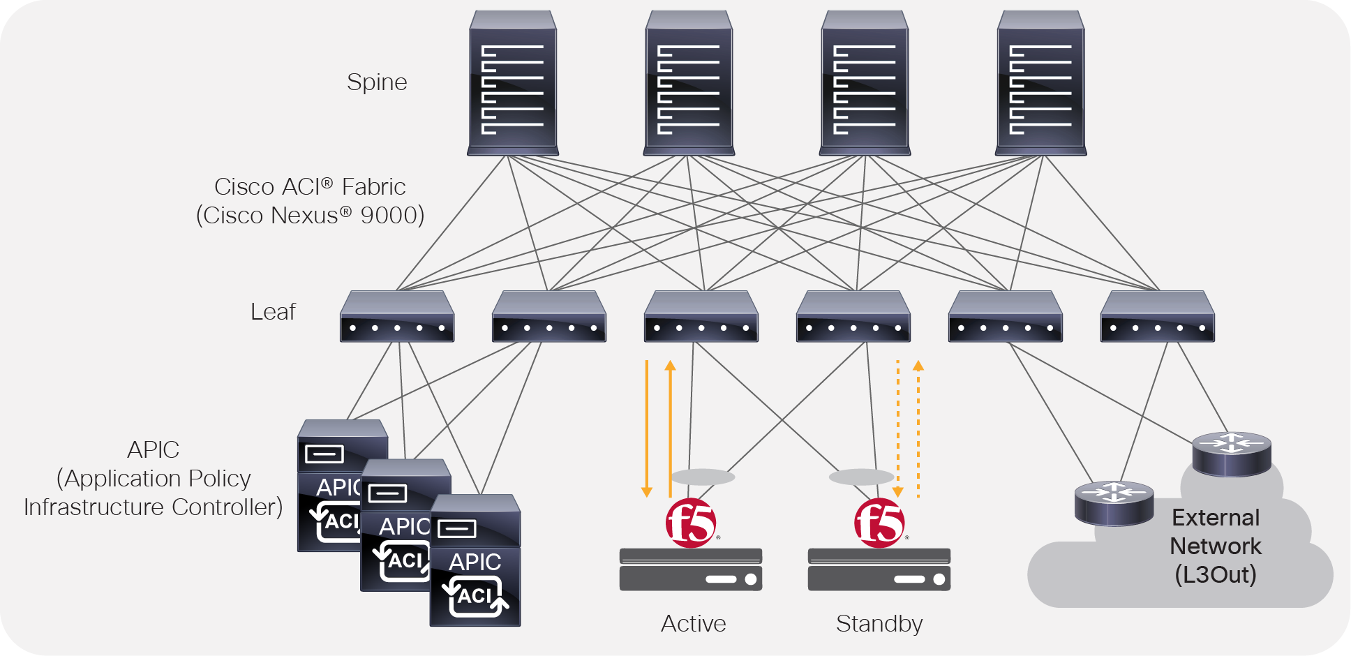
The physical Cisco ACI fabric is built on a Cisco Nexus® 9000 series spine-leaf design; its topology is illustrated in Figure 1, using a bipartite graph, where each leaf is a switch that connects to each spine switch, and no direct connections are allowed between leaf nodes and between spine nodes. The leaf nodes act as the connection point for all servers, storage, physical or virtual L4-L7 service devices, and external networks, and the spine acts as the high-speed forwarding engine between leaf nodes. Cisco ACI fabric is managed, monitored, and administered by the Cisco APIC.
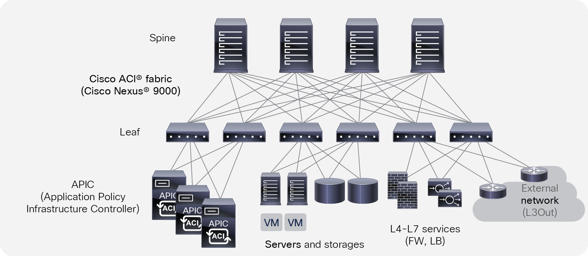
Cisco ACI topology
Cisco Nexus 9000 series switches that support ACI spine or leaf mode can be found at: https://www.cisco.com/c/en/us/products/switches/nexus-9000-series-switches/index.html
The minimum ACI fabric design should have two spine nodes, two leaf nodes, and three APICs. (Figure 1 illustrates four spine nodes and six leaf nodes.) The fabric design can scale up to 500 leaf nodes per ACI fabric. See the latest ACI verified scalability guide for details: https://www.cisco.com/c/en/us/support/cloud-systems-management/application-policy-infrastructure-controller-apic/tsd-products-support-series-home.html
Although Figure 1 shows a separate leaf node pair for APIC cluster, servers, storage, and others, it’s not mandatory to use a separate leaf node. Even though there is no specific role configuration on each leaf, a leaf connected to the external network is called a border leaf.
Cisco ACI logical constructs
Instead of configuring individual switches in a fabric, the logical network and security are provisioned and monitored as a single entity in the ACI fabric.
The fundamental security architecture of the ACI solution follows a whitelist model. A contract is a policy construct used to define communication between Endpoint Groups (EPGs) or Endpoint Security Groups (ESGs). Without a contract between EPGs/ESGs, no unicast communication is possible between those EPGs/ESGs by default. A contract is not required to allow communication between endpoints in the same EPG/ESG.
Unless otherwise indicated, the information in this document is applicable to both EPGs and ESGs, though EPGs are mainly used in statements and illustrations.
Figure 2 shows the relationship between EPGs and contracts.
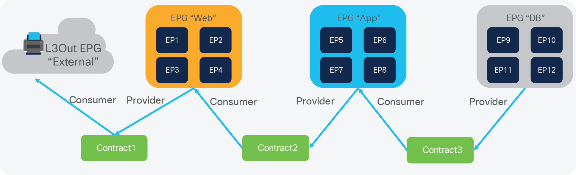
EPG and contracts
An EPG/ESG provides or consumes a contract (or provides and consumes a contract). For instance, the App EPG in the example in Figure 2 provides a contract that the Web EPG consumes and consumes a contract that the DB EPG provides.
An endpoint can belong to one EPG/ESG. Physical, virtual, and container endpoints can coexist in the same EPG/ESG. How to define which EPG/ESG an endpoint belongs to is based on EPG/ESG type:
● L3Out EPG - based on the IP subnet (longest prefix match)
● EPG - based on the leaf interface and Virtual LAN (VLAN) ID, or leaf interface and Virtual Extensible LAN (VXLAN)
● uSeg EPG (also called micro-EPG) - based on IP, MAC VM attributes such as VM name, or a combination of IP, MAC, and those attributes
● ESG - based on IP, IP subnet, tag, and EPG selector
For the external-to-ACI traffic, you can use a contract between an L3Out EPG and an ESG, but a contract between an EPG and an ESG is not supported.
Figure 3 illustrates ACI logical network design constructs. The tenant is a logical entity to construct EPGs, contracts, and network components for EPGs. Each EPG belongs to a Bridge Domain (BD) that is a broadcast domain boundary in ACI. A BD belongs to a VRF.
In this example, Web and App EPGs are in the same BD, BD1, and DB EPG is in a dedicated BD, BD2. Unlike traditional networks, multiple different EPGs can be in the same subnet as different security groups and zones.
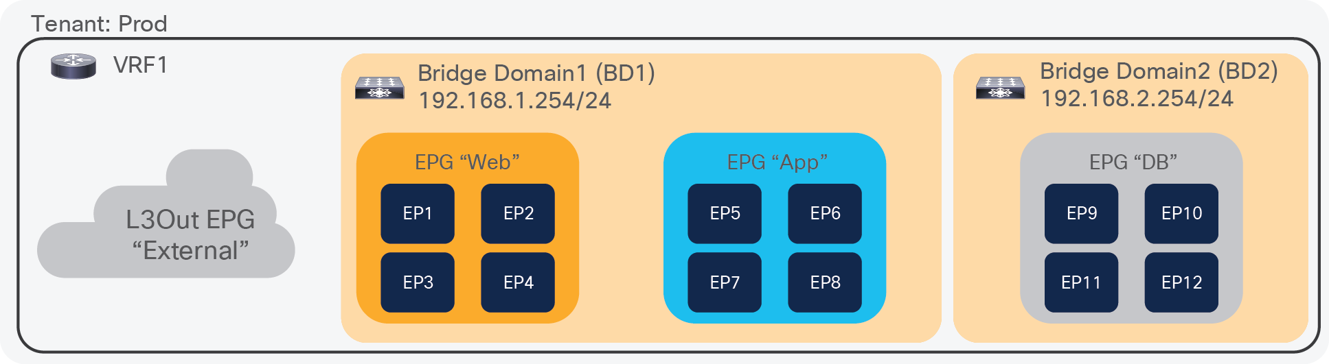
ACI logical network construct
Cisco ACI Service Graph and Policy-Based Redirect (PBR)
The Layer 4 – 7 Service Graph is a feature in Cisco ACI to insert Layer 4 – 7 service devices such as a firewall, load balancer, and IPS between the consumer and provider EPGs. Service Graph itself is not mandatory to design Layer 4 – 7 service devices in ACI, as long as the Layer 4 – 7 devices are inserted in the network using the general routing and bridging.
Figure 4 provides an example using routing and bridging to insert a load balancer without Service Graph. For incoming traffic from an endpoint in the consumer EPG, the VIP is routed by the ACI fabric. Why? Because the VIP is an ACI internal endpoint if the gateway of the server is the load balancer; the return traffic from an endpoint in the provider EPG is simply bridged by the ACI fabric.

Load balancer design without SNAT or PBR
If the load balancer interface and the servers are not in the same subnet, the use of SNAT on the load balancer can make the return traffic back to the load balancer. Even if the use of Service Graph is not mandatory in this case, the use of Service Graph offers these advantages:
● ACI automatically manages VLAN deployment on the ACI fabric and the virtual networks for service node connectivity.
● ACI automatically connects and disconnects virtual Network Interface Cards (vNICs) for virtual service appliances.
● ACI provides a more logical view of service insertion between consumer and provider EPGs.
● ACI can redirect traffic to the service node without the need for the service node to be the default gateway of the servers.
One of the main advantages of Service Graph is the PBR feature, which is helpful to insert Layer 4 – 7 service devices. With this PBR feature, ACI redirects traffic matched with the contract without relying on routing or bridging. For load balancer designs, PBR can be used for return traffic generated from the servers to make the return traffic go back to a load balancer that doesn’t perform SNAT.
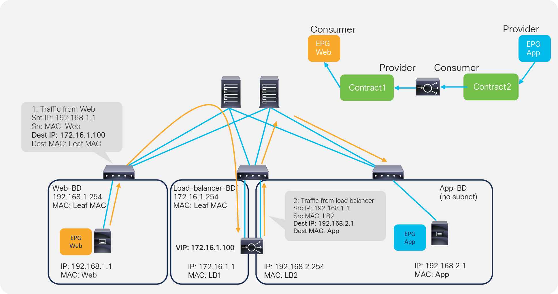
Figure 5 illustrates this with an example. The incoming traffic from an endpoint in a consumer EPG to VIP doesn’t require PBR because it’s routed to the VIP that is also an ACI internal endpoint. For the return traffic from an endpoint in the provider EPG, PBR is required if the load balancer didn’t perform SNAT on the incoming traffic. Without PBR, traffic would directly go back to the consumer endpoint, which prevents the load balancer from seeing both directions of the traffic.
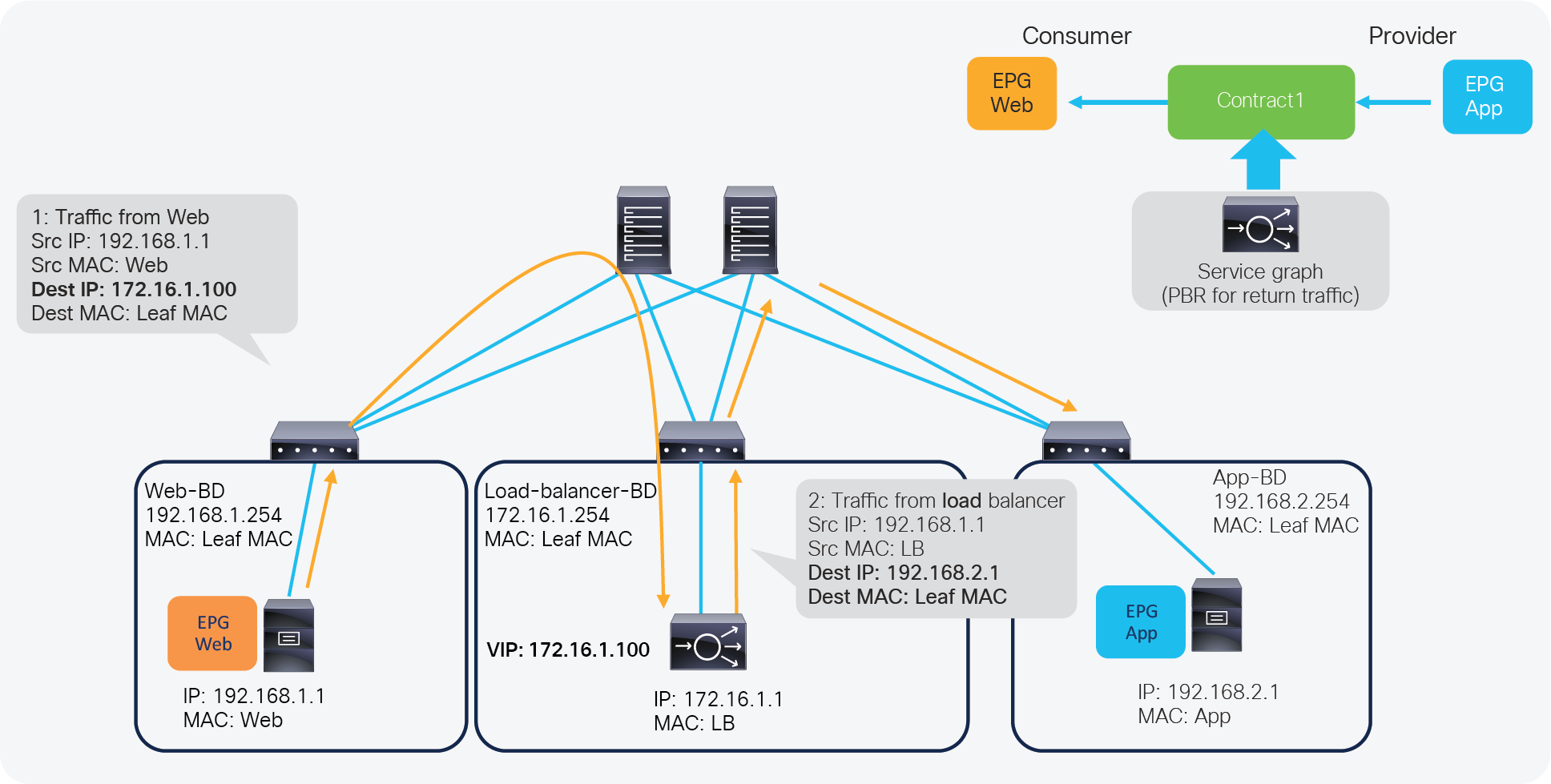
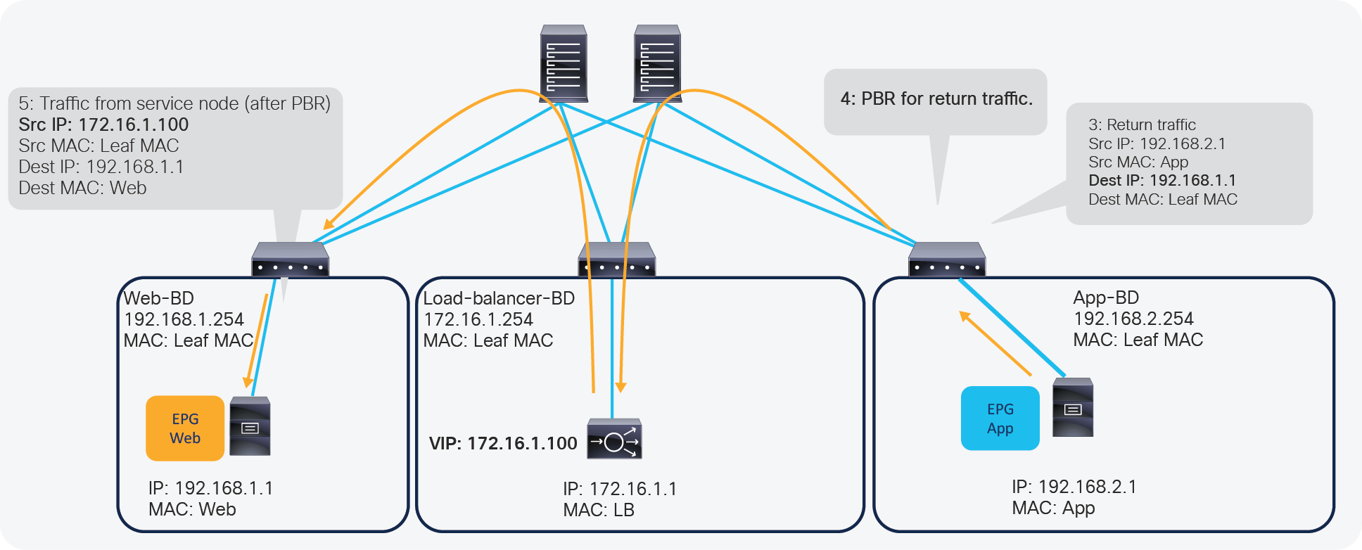
ACI Service Graph PBR use case for load balancer design
Note: Service Graph is mandatory in order to use PBR.
For more detailed information on Service Graph design and PBR, refer to the following white papers:
● Service Graph Design with Cisco Application Centric Infrastructure White Paper: https://www.cisco.com/c/en/us/solutions/collateral/data-center-virtualization/application-centric-infrastructure/white-paper-c11-2491213.html
● Cisco Application Centric Infrastructure Policy-Based Redirect Service Graph Design White Paper: https://www.cisco.com/c/en/us/solutions/data-center-virtualization/application-centric-infrastructure/white-paper-c11-739971.html
F5 BIG-IP is a family of products covering software and hardware designed around application availability, access control, and security solutions. When referring to BIG-IP this can mean a single software module in BIG-IP's software family or it could mean a hardware chassis sitting in your data center.
BIG-IP hardware
BIG-IP hardware offers several types of purpose-built custom solutions. There are two primary variations of BIG-IP hardware: single chassis design or VIPRION modular designs.
For more information refer to: https://www.f5.com/products/big-ip-services/iseries-appliance
BIG-IP software
BIG-IP software products are licensed modules that run on top of F5's Traffic Management Operation System (TMOS). This custom operating system is an event-driven operating system designed specifically to inspect network and application traffic and make real-time decisions based on the configurations you provide. The BIG-IP software can run on hardware or can run in virtualized environments. Virtualized systems provide BIG-IP software functionality where hardware implementations are unavailable, including public clouds and various managed infrastructures where rack space is a critical commodity.
There are a number of software modules offered by F5 BIG-IP. The BIG-IP Local Traffic Manager (LTM) is the software module that we focus on while discussing design and other considerations in this document.
BIG-IP LTM is central to F5's full traffic proxy functionality. It provides the platform for creating virtual servers, performance, service, protocol, authentication, and security profiles to define and shape application traffic. Most other software modules in the BIG-IP family use LTM as a foundation for enhanced services.
All variations of BIG-IP hardware and software work with Cisco ACI. If the virtual edition of BIG-IP is being used, a VMM integration, such as VMware vSphere or Microsoft SCVMM, can be done with Cisco APIC.
For ACI VMM domain integration, see the Cisco ACI Virtualization Guide at: https://www.cisco.com/c/en/us/support/cloud-systems-management/application-policy-infrastructure-controller-apic/tsd-products-support-series-home.html and review the ACI network design options for load balancer.
This section explains typical network design options for load balancer in general and then explains how to translate these options to an ACI network construct.
Overview
When inserting a load balancer into a Cisco ACI fabric, it is important to understand the desired traffic flow. There are two main types of traffic patterns to consider:
1. Incoming and return traffic go through the same load balancer that is a stateful device
2. The traffic to the other VIP goes via a load balancer and the return traffic from servers goes directly back to the client: this is called Direct Server Return (DSR)
Following is a list of questions that helps to understand the requirement.
● Is the load balancer deployed in Layer 2 or Layer 3 mode? (F5 BIG-IP supports both Layer 2 and Layer 3 - see https://support.f5.com/csp/article/K55185917)
● How is the return traffic handled? Is the load balancer the gateway? Is the load balancer doing SNAT? Is ACI PBR redirecting the traffic to the load balancer or is the load balancer deployed in DSR mode?
● What High-Availability (HA) option is used for the load balancer - active/standby HA pair, active/active HA pair, or multiple HA pairs?
● Is the VIP in the same subnet range as the IP address of a load balancer interface (F5 BIG-IP calls it “self-IP”) or outside of the subnet range?
● What are the dynamic routing protocol requirements? Is Route Health Injection (RHI) required or not?
In this document, the assumption is that the load balancer is deployed in Layer 3 mode with active/standby HA because this represents the majority of the deployments.
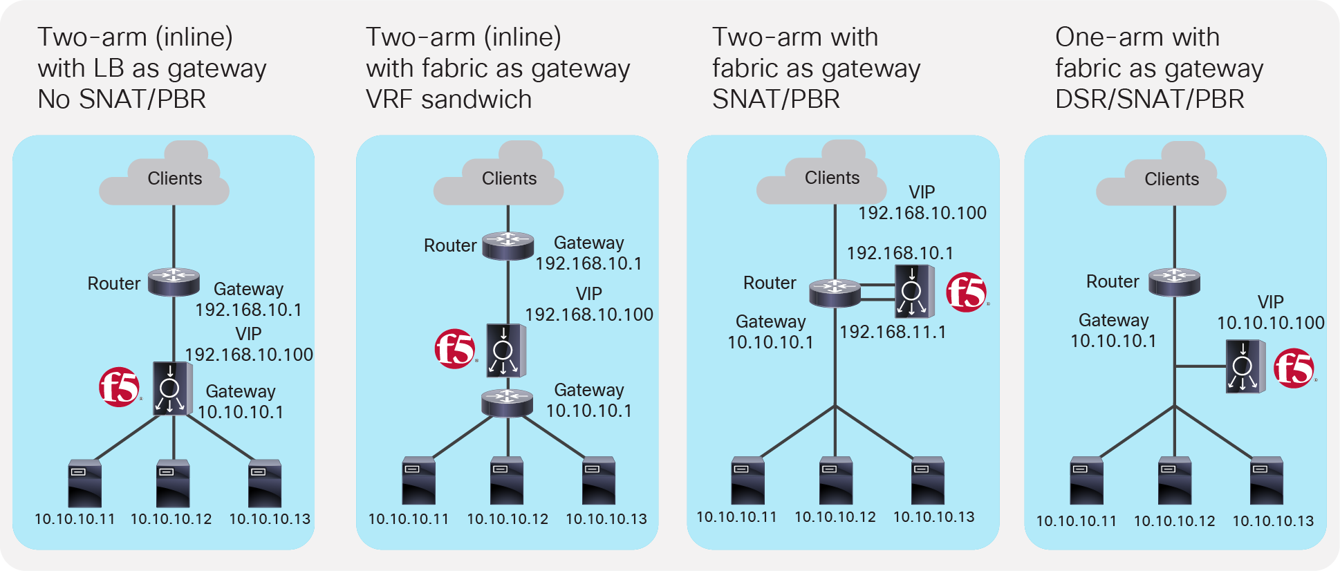
Figure 6 illustrates common load balancer network design options.
● In the first example on the left side of the image, the load balancer is deployed in two-arm mode and it is the default gateway of the servers. SNAT or PBR is not required because the load balancer is in the traffic path based on routing.
● In the second example, the load balancer is deployed in two-arm mode and it is placed between two different routers or VRFs: one is for external connectivity and the other is the gateway of servers. SNAT or PBR is not required because the load balancer is in the traffic path based on routing.
● In the third example, the load balancer is deployed in two-arm mode in a way that not all traffic from the servers has to go via the load balancer itself. SNAT or PBR is required to make return traffic back to the load balancer. If neither SNAT nor PBR is used, the return traffic would go back to the client directly, and as a result, the traffic would be dropped by the client. The reason: because the source IP address of the return traffic (of the server) is different from the destination IP address of the incoming traffic sent by the client, which was directed to the VIP.
● In the fourth example, the load balancer is deployed in one-arm mode in a way that not all traffic from the servers has to go via the load balancer itself. SNAT or PBR is required to make return traffic back to the load balancer. If neither SNAT nor PBR is used, the return traffic goes back to the client directly, which will be dropped by the client because the source IP address of the return traffic is different from the destination IP address of the incoming traffic sent by the client. The load balancer interface can be in the same or a different subnet with servers. This design can be used for Layer 2 DSR, where the return traffic doesn’t go back via the load balancer. For Layer 2 DSR, the load balancer and servers must be in the same subnet.
Typical load balancer design options
Load balancer designs are often categorized using the terminology “two-arm” and “one-arm”. From the load balancer’s perspective, the number of arms is nothing more than the number of interfaces or VLAN interfaces that are created on the load balancer. There should be no significant difference between the two modes from a load balancer performance perspective. In the case of a two-arm design, traffic from the client arrives on an interface on the load balancer and is forwarded to a server through the other interface. In the case of a one-arm design, traffic arrives and leaves using the same interface on the load balancer.
The following sub-sections explain how to translate the typical load balancer design options just described into ACI network constructs. Table 1 summarizes the comparison of the design options in a Cisco ACI fabric.
In these examples, the load balancer external interface IP and the VIP are in the same subnet. For the case where they are not in the same subnet, refer to the VIP outside of the self IP subnet range section. Even if the examples reference north-south traffic flows, which is traffic from the outside to internal servers through a VIP, the same design considerations can also be applied to east-west traffic flows, which is traffic from internal servers to other internal severs through a VIP.
Table 1. Typical load balancer design options in Cisco ACI fabric
|
|
How to make the return traffic go back via the Load Balancer (LB) |
Design |
Benefit |
Consideration |
| LB is the gateway for the servers |
Use LB as the gateway for the servers associated to the VIP |
Simple network design |
Inter-subnet traffic must go through the load balancer. |
|
| LB as routing next hop (VRF sandwich) |
Use the ACI fabric as a gateway for the servers associated to the VIP. LB is routing next hop of the ACI fabric. |
Take advantage of the ACI anycast gateway. |
Need to manage two VRFs |
|
| SNAT or PBR |
Use the ACI fabric as a gateway for the LB and also for the servers associated to the VIP. Use SNAT or PBR to make return traffic go back via the LB. |
Take advantage of the ACI anycast gateway. Selective traffic redirection by using PBR |
Service Graph is mandatory to use PBR |
|
| SNAT or PBR |
Use the ACI fabric as a gateway for the LB and also for the servers associated to the VIP. Use SNAT or PBR to make return traffic back to load balancer. |
Take advantage of the ACI anycast gateway. Selective traffic redirection by using PBR |
Service Graph is mandatory to use PBR |
(the details are not covered in this document.)
Two-arm (inline) load balancer as gateway
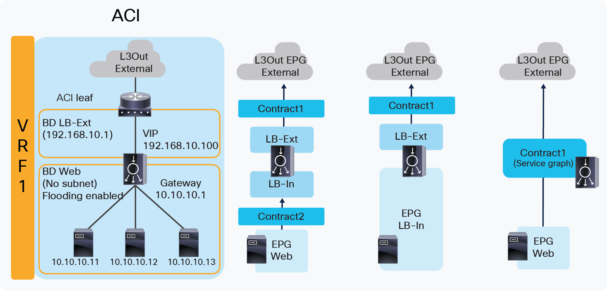
The first example is one where the two-arm inline load balancer is the default gateway of the servers. SNAT or PBR is not required because the load balancer is in the traffic path based on routing. In this case, two VLAN segments are required. Thus, in case of ACI, you need to use two bridge domains: one is for the load balancer external interface and the other is for the load balancer internal interface. Figure 7 provides an example of this scenario. In this example, the load balancer VIP and the load balancer external interface IP are in the same subnet.
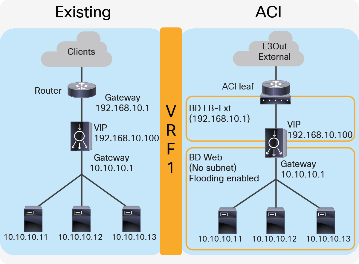
Two-arm (inline) load balancer as gateway
“LB-Ext” bridge domain for the load balancer external interface has the bridge domain subnet that is the gateway for the load balancer to the external network through L3Out. The “Web” bridge domain for the load balancer internal interface and the servers doesn’t have a bridge domain subnet because the load balancer internal IP address is the gateway for the servers. The L3Out connected to the external network has the L3Out EPG “External” with the external network subnets that are allowed to access the load balancer VIP in the “LB-Ext” bridge domain.
The traffic coming from the external network arrives to the ACI fabric and it is routed to the VIP (192.168.10.100) because the VIP is an ACI local endpoint in “LB-Ext” bridge domain. The traffic is then load balanced to one of the servers associated to the VIP. The return traffic from the server arrives on the load balancer internal interface because it is the gateway of the servers. The load balancer then routes the traffic back to the ACI fabric that is the gateway of the load balancer to the external network.
Figure 8 illustrates the contract configuration for this design. To permit end-to-end traffic, one of the following configurations is required:
● Two contracts – One is between the L3Out EPG “External” for the external network and the EPG “LB-Ext” for the load balancer external interface, and the other is between the EPG “LB-In” for the load balancer internal interface and “Web” EPG for the servers. All EPGs are created by a user.
● One contract – If there is no security requirement, the load balancer internal interface and the servers can be combined into one EPG instead of different EPGs with a contract. All EPGs are created by a user.
● Service Graph – Use Service Graph on a contract between the L3Out EPG “External” for the external network and “Web” EPG. The EPGs (called “internal service EPGs” or “shadow EPGs”) for the load balancer external and internal interfaces are automatically created through Service Graph rendering. The internal service EPGs are not displayed in the GUI, and the user doesn’t need to manage them.
Two-arm (inline) load balancer as gateway (ACI network and contract design)
Highlights of key characteristics of this design:
● The load balancer internal interface and the EPG for the servers are in the same bridge domain (ACI is used for bridging)
● ACI can be used as the next hop for the external side of the load balancer
● All inter-subnet traffic goes through the load balancer
● SNAT or PBR is not required
● Service Graph is not mandatory
Two-arm (inline) load balancer with fabric as gateway
This design consists of a two-arm inline load balancer placed between two routing instances, such as two separate routers or two VRFs. The internal facing routing instance provides the gateway to the servers. SNAT or PBR is not required because the load balancer is in the traffic path based on routing. In the case of ACI, you can use two VRFs (instead of using an external router): one is for the load balancer external interface and the other is for the load balancer internal interface. The two VRFs configured in ACI are not for the purpose of multitenancy, but simply to route traffic via the load balancer. No inter-VRF route-leaking configuration is required on the ACI fabric itself because the load balancer is in between VRFs.
Figure 9 provides an example of this configuration. In this example, the load balancer VIP and the load balancer external interface IP are in the same subnet.
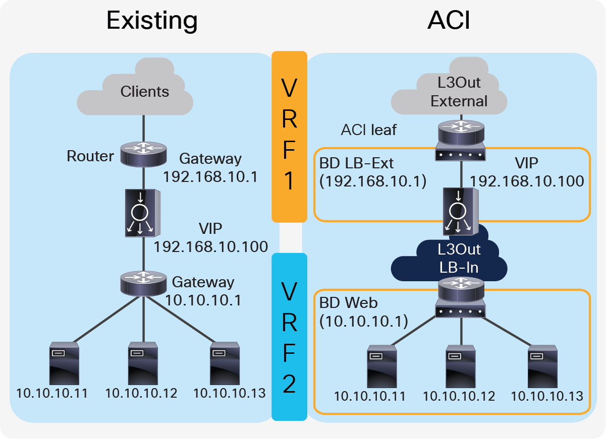
Two-arm (inline) load balancer with the fabric as gateway
The external-facing VRF, “VRF1”, has the L3Out connected to the external network and the L3 bridge domain, “LB-Ext”, that has the gateway for the load balancer to the external network. The L3Out connected to the external network has the L3Out EPG “External” with the external network subnets that are allowed to access to the load balancer VIP in the “LB-Ext” bridge domain. The internal-facing VRF, “VRF2”, has the L3 bridge domain, “Web”, that is the gateway for the servers and the L3Out “LB-In” for the load balancer internal interface connectivity. The L3Out “LB-In” has the L3Out EPG “LB-In” with the external network subnets that are allowed to access to the servers through the load balancer.
The traffic coming from the external network arrives on the ACI fabric on VRF1 and it is routed to the VIP (192.168.10.100) because the VIP is an ACI local endpoint in “LB-Ext” bridge domain. Traffic is then load balanced to one of the servers associated to the VIP. The load balancer must have a route to the server subnet (10.10.10.0/254). This load balancer route uses the ACI IP address on the L3Out logical interface of the L3Out “LB-In” and then traffic arrives on the servers in VRF2. The return traffic from the server arrives on the ACI fabric via the “Web” bridge domain on VRF2 because the “Web” bridge domain subnet is the gateway of the servers. ACI VRF2 must have a route to the external network via the load balancer internal interface. Then, the load balancer routes the traffic back to the ACI leaf that is the gateway of the load balancer to the external network.
If the load balancer does SNAT and uses the load balancer internal IP subnet range as NATe’d IP, the load balancer internal interface can be in a bridge domain instead of an L3Out because the NATe’d IP is a local endpoint IP in VRF2 that doesn’t require an additional route.
Figure 10 illustrates the contract configuration for this design. To permit end-to-end traffic, one of the following configurations is required:
● Two contracts – One is between the L3Out EPG “External” for the external network and the EPG “LB-Ext” for the load balancer external interface, and the other is between the L3Out EPG “LB-In” for the load balancer internal interface and “Web” EPG for the servers. All EPGs are created by a user.
● Service Graph – Use of Service Graph on a contract between the L3Out EPG “External” for the external network and “Web” EPG. L3Out EPG “LB-In” for the load balancer internal interface needs to be created separately and is selected in the Service Graph. The EPG “LB-Ext”, internal service EPG, for the load balancer external interface is automatically created through Service Graph rendering. The internal service EPG is not displayed in the GUI, and the user doesn’t need to manage it.
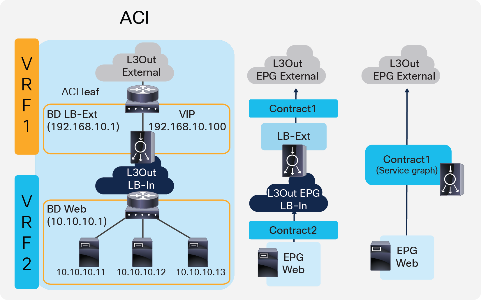
Two-arm (inline) load balancer with fabric as gateway (ACI network and contract design)
Key characteristics of this design:
● This is the traditional VRF sandwich design
● ACI is used for routing
● The external interface of the load balancer is connected to a bridge domain via an EPG
● The internal interface of the load balancer is connected to a L3Out via a L3Out EPG
● All inter-VRF traffic goes through the load balancer
● SNAT or PBR is not required
● Service Graph is not mandatory
● If SNAT is enabled on the load balancer using the internal interface subnet range as NAT’ed IP, L3Out for the internal interface of the load balancer is not required
Two-arm load balancer with fabric as the gateway
This design describes the integration with a two-arm load balancer in a way that not all traffic from the servers has to go via the load balancer itself. SNAT or PBR is required to make the return traffic go back to the load balancer. Without the use of SNAT or PBR, the return traffic from the servers would bypass the load balancer and then the client that receives the return traffic doesn’t handle the traffic as the reply because the source IP address of the return traffic is different from the destination IP address of the traffic sent by the client.
Figure 11 provides an example of this scenario. This example consists three bridge domains: one is for the external interface of the load balancer, another is for the internal interface of the load balancer, and the third is for the servers. If the servers and the internal interface of the load balancer are in the same subnet, the two bridge domains can be combined to one bridge domain. In this example, the load balancer VIP and the load balancer external interface IP are in the same subnet.
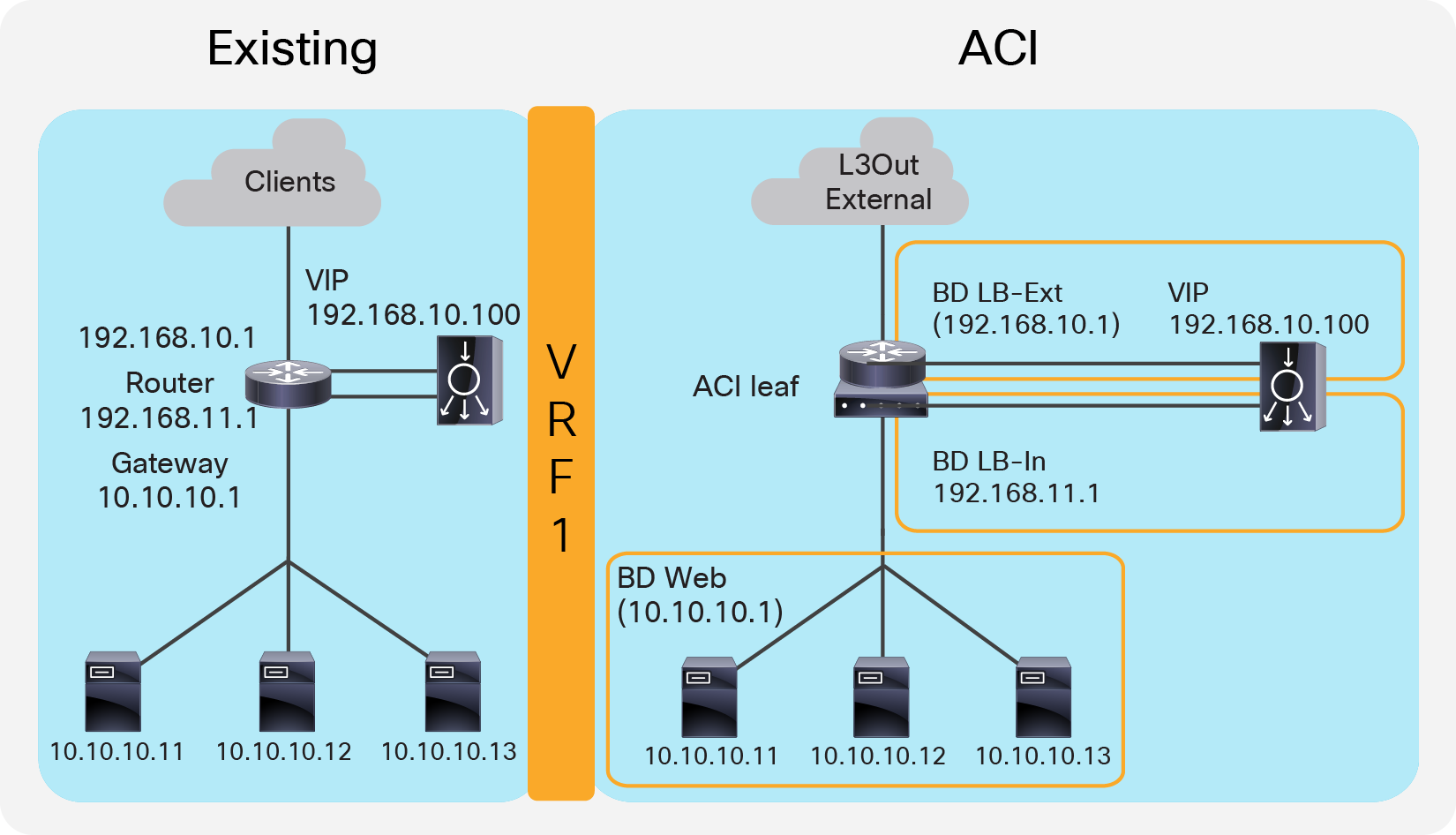
Two-arm (inline) load balancer with fabric as gateway
The “LB-Ext” bridge domain for the load balancer external interface has the bridge domain subnet that is the gateway for the load balancer to the external network. The “LB-In” bridge domain for the load balancer internal interface has the bridge domain subnet that is the gateway for the load balancer to the server network. The “Web” bridge domain for the servers has the bridge domain subnet that is the gateway for the servers. The L3Out connected to the external network has the L3Out EPG “External” with the external network subnets that are allowed to access the load balancer VIP in the “LB-Ext” bridge domain.
The traffic coming from the external network arrives on the ACI fabric and is routed to the VIP (192.168.10.100) because the VIP is an ACI local endpoint in the “LB-Ext” bridge domain. The traffic is then load balanced to one of the servers associated to the VIP. The load balancer must have the route to the server subnet (10.10.10.0/254) via the “LB-In” bridge domain subnet IP. The return traffic from the server arrives on the “Web” bridge domain subnet IP because it is the gateway for the servers. SNAT or PBR is required to make the return traffic go back to the load balancer. If SNAT was enabled on the load balancer, the destination IP of the return traffic will be at the IP in the “LB-In” bridge domain, which is owned by the load balancer (for example, 192.168.11.10), so that the return traffic is routed and sent to the load balancer internal interface. If PBR is enabled for the return traffic, PBR is applied on the traffic from the “Web” EPG to L3Out EPG “External”. As a result, that traffic is redirected to the load balancer internal interface. The load balancer then routes the return traffic back to the ACI fabric “LB-Ext” bridge domain subnet IP that is the gateway of the load balancer to the external network.
Figure 12 illustrates the contract configuration for this design. To permit end-to-end traffic, one of the following configurations is required:
● Two contracts (SNAT on the load balancer) – One is between the L3Out EPG “External” for the external network and the EPG “LB-Ext” for the load balancer external interface, and the other is between the EPG “LB-In” for the load balancer internal interface and the “Web” EPG.
● Service Graph (PBR for return traffic) Use Service Graph PBR on a contract between the L3Out EPG “External” for the external network and the “Web” EPG. The EPGs (called “internal service EPGs” or “shadow EPGs”) for the load balancer external and internal interfaces are automatically created through Service Graph rendering. The internal service EPGs are not displayed in the GUI, and the user doesn’t need to manage them.
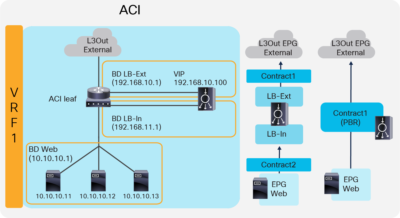
Two-arm (inline) load balancer with fabric as gateway (ACI network and contract design)
The following points summarize some key characteristics of this design:
● ACI provides routing for the servers and the load balancer; it is their default gateway or routing next hop.
● PBR or SNAT is required.
● The service device can be in the same bridge domain as the servers or in a different bridge domain.
● If PBR is used to make the return traffic go back to the load balancer, Service Graph is mandatory and specific traffic is redirected to the load balancer internal interface.
● If SNAT is used to make the return traffic go back to the load balancer, the NATe’d IP must be in the load balancer internal side subnet range.
One-arm load balancer with fabric as the gateway
This design describes the integration with a one-arm load balancer in a way that not all traffic from the servers has to go via the load balancer itself. SNAT or PBR is required to make the return traffic go back to the load balancer. Without the use of SNAT or PBR, the return traffic from the servers would bypass the load balancer and then the client that receives the return traffic doesn’t handle the traffic as the reply because the source IP address of the return traffic is different from the destination IP address of the traffic sent by the client.
Note: This design can also provide Layer 2 DSR, where the return traffic from the servers directly go back to the client without going through the load balancer. The Layer 2 DSR design requires the load balancer and servers to be in the same subnet; that the VIP is configured as a loopback address on the server; and that the server is configured not to answer ARP requests for the VIP. This document mainly explains designs with SNAT or PBR. Refer in ACI Fabric Endpoint Learning white paper for Layer 2 DSR design considerations in ACI.
Figure 13 provides an example of this scenario. This example consists one bridge domain for the load balancer interface and the servers. The load balancer VIP and the load balancer external interface IP are in the same bridge domain subnet in this example, but they can be in different bridge domains if needed.
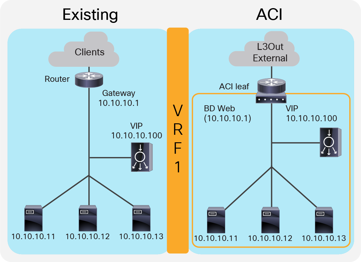
One-arm (inline) load balancer with fabric as gateway
The “Web” bridge domain that is configured with a subnet is the gateway for the load balancer itself and for the servers. The L3Out connected to the external network has the L3Out EPG “External” with the external network subnets that are allowed to access to the load balancer VIP in the “Web” bridge domain.
The traffic coming from the external network arrives on the ACI fabric and is routed to the VIP (10.10.10.100) because the VIP is an ACI local endpoint in the “Web” bridge domain. The traffic is then load balanced to one of the servers associated to the VIP. The return traffic from the server arrives on the “Web” bridge domain subnet IP because it is the gateway for the servers. SNAT or PBR is required to make the return traffic back to the load balancer. If SNAT is enabled on the load balancer, the destination IP of the return traffic is the IP in the “Web” bridge domain, which is owned by the load balancer (for example, 10.10.10.10). ACI bridges the traffic from the servers to the load balancer. If PBR is enabled for the return traffic, PBR is applied on the traffic from the “Web” EPG to the L3Out EPG “External”. ACI redirects the traffic to the load balancer internal interface. The load balancer then routes the return traffic back to the subnet IP address of the “Web” bridge domain.
Figure 14 illustrates the contract configuration for this design. To permit end-to-end traffic, one of the following configurations is required:
● Two contracts (SNAT on the load balancer) – One is between the L3Out EPG “External” for the external network and the EPG “LB” for the load balancer interface, and the other is between the EPG “LB” for the load balancer interface and “Web” EPG.
● One contract (SNAT on the load balancer) – If the interface of the load balancer and the servers is in the same bridge domain and there is no security requirement, they can be combined to one EPG instead of different EPGs with a contract.
● Service Graph with PBR for return traffic – This design uses Service Graph PBR on a contract between the L3Out EPG “External” for the external network and the “Web” EPG. The EPG (called “internal service EPG” or “shadow EPG”) for the load balancer interface is automatically created through Service Graph rendering. The internal service EPG is not displayed in the GUI, and the user doesn’t need to manage them.
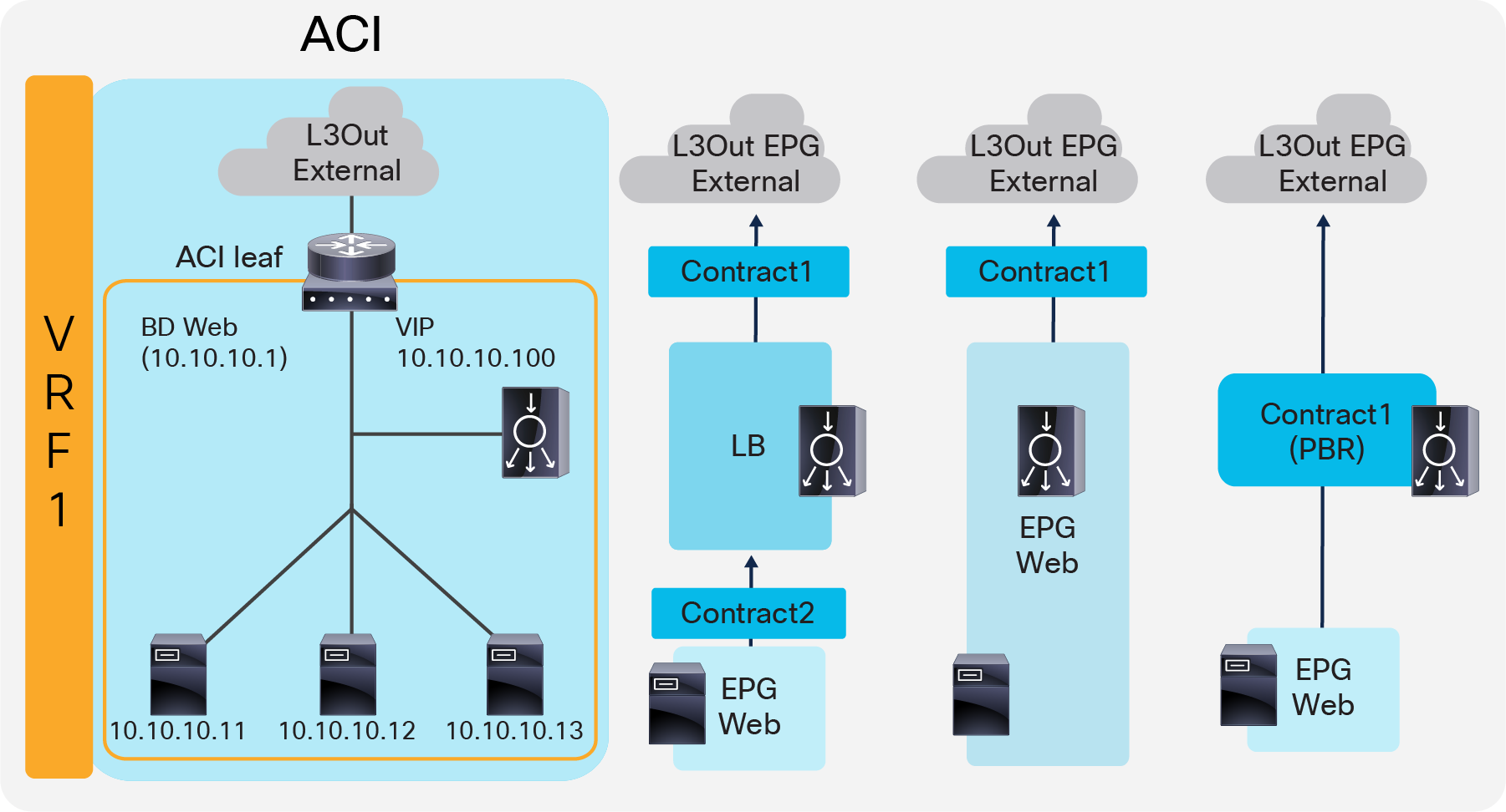
One-arm (inline) load balancer with fabric as gateway (ACI network and contract design)
The following points summarize key characteristics of this design:
● ACI provides routing for the servers and the load balancer; it is their default gateway or routing next hop.
● PBR or SNAT is required.
● The service device can be in the same or different BDs with the servers.
● If PBR is used to make the return traffic go back to the load balancer, Service Graph is mandatory and specific traffic is redirected to the load balancer internal interface.
● If SNAT is used to make the return traffic go back to the load balancer, the NATe’d IP must be in the load balancer interface subnet range.
VIP outside of the self IP subnet range
The previous four design examples are based on the assumption that the VIP address is in the load balancer interface local subnet range. The VIP can also belong to a different subnet than the load balancer interface local subnet range, especially if the VIP is a public IP address. In this case, the ACI fabric needs to know the route to the VIP because it is not a local endpoint IP in a bridge domain.
To add a route to the VIP on an ACI fabric, three options are available:
● Add a secondary IP on the bridge domain of the EPG for the load balancer external interface. This option requires you to allocate the VIP subnet range in the ACI bridge domain, which might not be preferable if VIP is a public IP address or if multiple VIPs in the same subnet are owned by different load balancers across different networks.
● Add a /32 static route on the EPG for the load balancer external interface. This option supports /32 static route only. If you need a VIP subnet range or RHI, you need to use a L3Out to connect the load balancer external interface instead of this option. This option is available on an EPG created by a user. As of Cisco APIC Release 5.2, this option is not available in an internal service EPG created through Service Graph rendering.
● Use an L3Out to add a static route or to establish dynamic routing neighborship with the load balancer. This option requires a L3Out configuration for load balancer interface connectivity. This option supports Route Health Injection (RHI), which requires dynamic routing to advertise the VIP from the load balancer.
The first two options don’t require an L3Out, hence the network design is the same as the examples already covered. As a result, this section focuses on designs using an L3Out.
Note: This document does not cover how to create L3Out and L3Out design considerations. Refer to the ACI Fabric L3Out Guide for details: https://www.cisco.com/c/en/us/solutions/collateral/data-center-virtualization/application-centric-infrastructure/guide-c07-743150.html
Two-arm (inline) load balancer as gateway
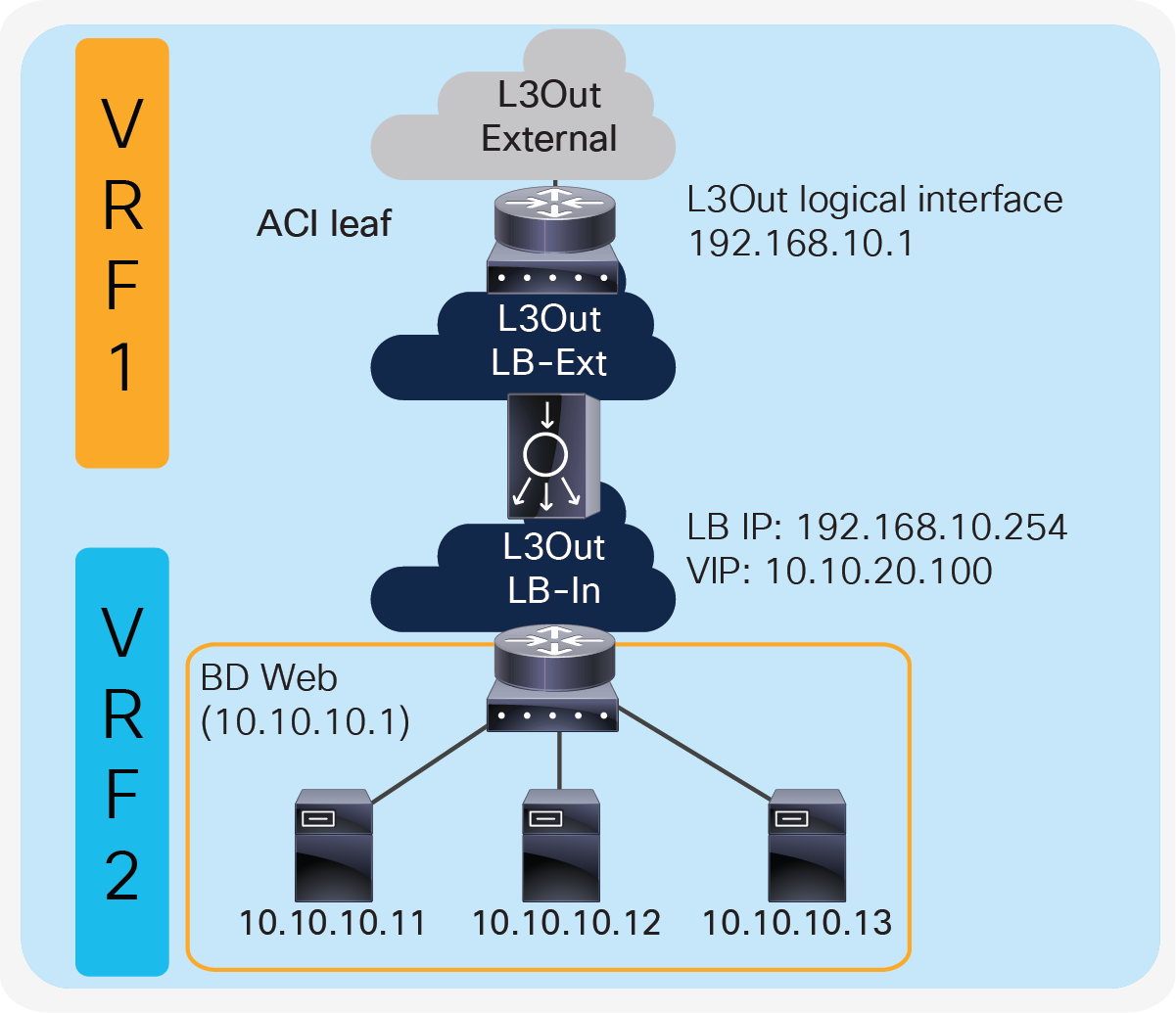
Figure 15 illustrates this design with an example. The VIP 10.10.20.100 is outside of the load balancer external interface local subnet, 192.168.10.0/24. ACI L3Out “LB-Ext” for the load balancer external interface connectivity is used to add the route onto the ACI fabric to reach VIP 10.10.20.100 via 192.168.10.254 that is the load balancer external interface IP. If RHI is enabled on the load balancer, use of dynamic routing on the L3Out “LB-Ext” is required to establish dynamic routing peering between the ACI border leaf node and the load balancer.
Two-arm (inline) load balancer as gateway
Two-arm (inline) load balancer with the ACI fabric as gateway
Figure 16 provides an example of this setup. The VIP 10.10.20.100 is outside the load balancer external interface local subnet, 192.168.10.0/24. ACI L3Out “LB-Ext” in VRF1 for the load balancer external interface connectivity is used to add the route on the ACI fabric VRF1 to reach VIP 10.10.20.100 via 192.168.10.254 that is the load balancer external interface IP. If RHI is enabled on the load balancer, use of dynamic routing on the L3Out “LB-Ext” is required to establish dynamic routing peering between the ACI border leaf node for VRF1 and the load balancer.
Two-arm (inline) load balancer with fabric as gateway
Two-arm load balancer with fabric as gateway
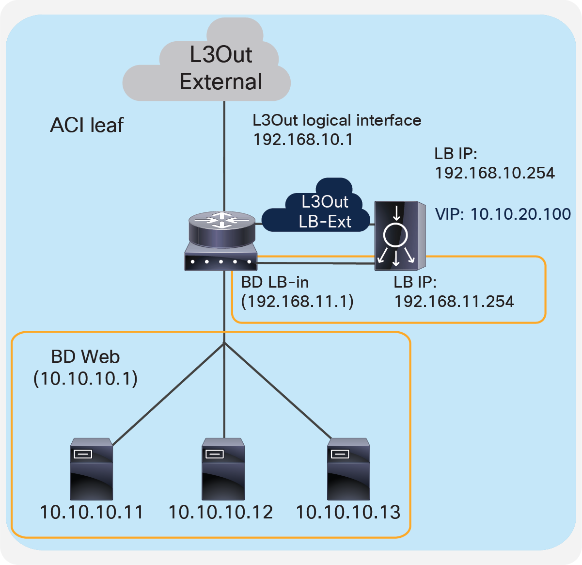
Figure 17 provides an example of this setup. The VIP 10.10.20.100 is outside of the load balancer external interface local subnet, 192.168.10.0/24. ACI L3Out “LB-Ext” for the load balancer external interface connectivity is used to add the route on the ACI fabric to reach VIP 10.10.20.100 via 192.168.10.254 that is the load balancer external interface IP. If RHI is enabled on the load balancer, use of dynamic routing on the L3Out “LB-Ext” is required to establish dynamic routing peering between the ACI border leaf node and the load balancer.
Either SNAT or PBR can be used to make the return traffic go through the load balancer. If PBR is used to redirect return traffic (from the provider “Web” EPG to the consumer L3Out EPG “External” for an external network) to the load balancer internal interface, it requires the unidirectional PBR feature that is available in Cisco APIC Release 5.0.
Two-arm load balancer with fabric as gateway
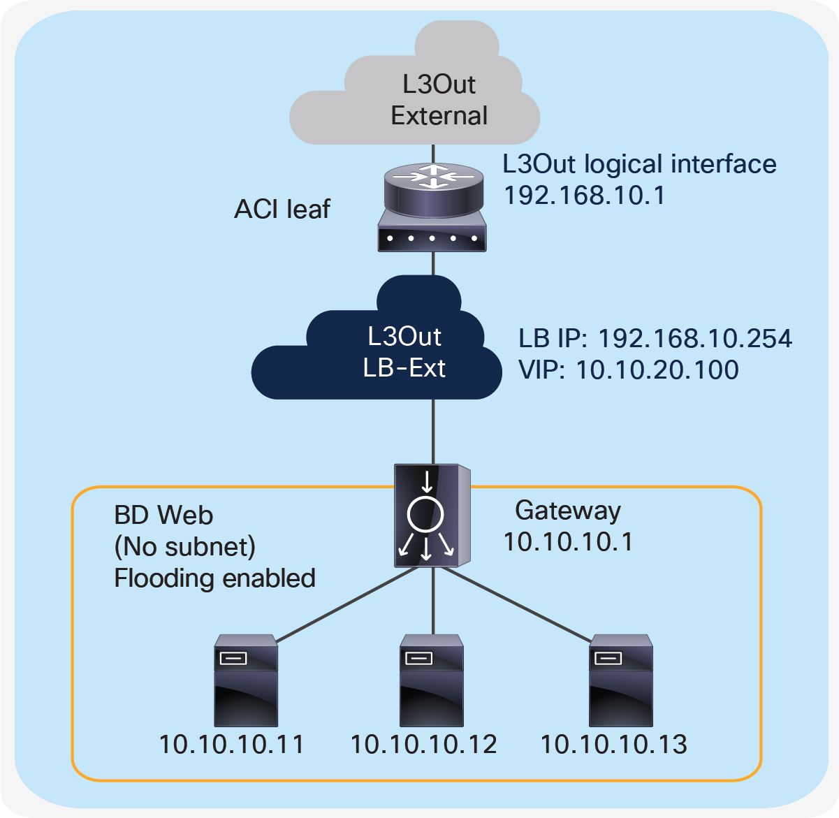
One-arm load balancer with fabric as gateway
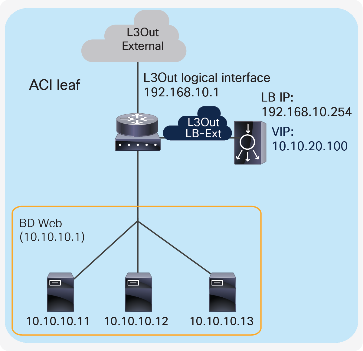
If L3Out “LB-Ext” is used for one-arm load balancer connectivity, the servers and the load balancer interface should be in different subnets because the servers would also need to be in the same L3Out.
Figure 18 provides an example what this looks like. The VIP 10.10.20.100 is outside the load balancer interface local subnet, 192.168.10.0/24. The L3Out “LB-Ext” for the load balancer interface is used to add the route on the ACI fabric to reach VIP 10.10.20.100 via 192.168.10.254 that is the load balancer interface IP. If RHI is enabled on the load balancer, use of dynamic routing on the L3Out “LB-Ext” is required to establish dynamic routing peering between the ACI border leaf nodes and the load balancer.
Prior to APIC Release 5.2, ACI PBR can redirect traffic to a load-balancer interface that is connected to a bridge domain, and not the interface on an L3Out; therefore, SNAT must be enabled on the load balancer. Starting from APIC Release 5.2, ACI PBR can be enabled to redirect traffic to a load-balancer interface that is connected via an L3Out.
One-arm load balancer with fabric as gateway
This section explains the following F5 design considerations, which can be applied to the design options already discussed in this document:
● Choice of High-Availability (HA) and failover mode
● Choosing whether to configure the F5 interface with a floating MAC (MAC masquerade)
● Choosing to route traffic based on the ARP resolution on the next hop or from the MAC learned on the incoming traffic (Auto Last Hop, also known as source MAC-based forwarding)
● Whether to enable Link Layer Discovery Protocol (LLDP) on the BIG-IP
● Tuning IP aging on ACI
High availability (HA)
A redundant system is a type of BIG-IP system configuration that allows traffic processing to continue if a BIG-IP device in the redundant system becomes unavailable. A BIG-IP redundant system consists of two identically configured BIG-IP devices. When an event occurs that prevents one of the BIG-IP devices from processing network traffic, the peer device in the redundant system immediately begins processing that traffic, and users experience no interruption in service.
You can configure the devices of a redundant system to run in one of two redundancy modes: active/standby mode and active/active mode.
Active/standby mode
With active/standby mode, only one of the two devices is in an active state that is processing traffic at any given time. The inactive device serves strictly as a standby device, becoming active only if the active device becomes unavailable. When a standby device becomes active, it normally remains active until an event occurs that requires the other device to become active again, or until you specifically force it into a standby state. Active/standby mode is the recommended mode for redundant system configuration.
Active/standby BIG-IP topology
Active/active mode
With active/active mode, both devices are in an active state simultaneously; each device processes traffic for different virtual servers (VIPs) or SNATs. If an event prevents one of the devices from processing traffic, the other device begins processing that traffic in addition to its own. In this mode, both devices actively process application traffic, each for a different application.
A traffic group is a collection of related IP addresses that move between F5 BIG-IP in a high-availability failover event. Traffic groups are synced between BIG-IPs in an HA pair. A BIG-IP device in the HA pair processes its application traffic using the configuration objects associated with the default floating traffic group, traffic-group-1. By default, this traffic group contains the floating self-IP addresses of the default VLANs. The other BIG-IP device in the HA pair processes its application traffic using a second traffic group. If one of the devices becomes unavailable for any reason, the other device automatically begins processing traffic for the unavailable peer device, while continuing to process the traffic for its own application.
A device group is a collection of BIG-IP devices that are configured to securely synchronize their BIG-IP configuration data and fail over when needed. You can create a sync-failover and a sync-only device group type.
A sync-failover device group contains devices that synchronize configuration data and support traffic groups for failover purposes. A sync-failover device group supports a maximum of eight devices.
A sync-only device group contains devices that synchronize configuration data but do not synchronize failover objects and do not fail over to other members of the device group.
Figure 20 provides an example of the device group named Device Group 2. This device group contains two BIG-IP devices, Device 1 and Device 2.
The configuration shows two traffic groups, traffic-group-1 and traffic-group-2, each containing failover objects. For traffic-group-1, Device 1 is the default device. For traffic-group-2, Device 2 is the default device. If Device 1 becomes unavailable, all objects in traffic-group-1 float (become active) on Device 2. If Device 2 becomes unavailable, traffic-group-2 floats to Device 1.
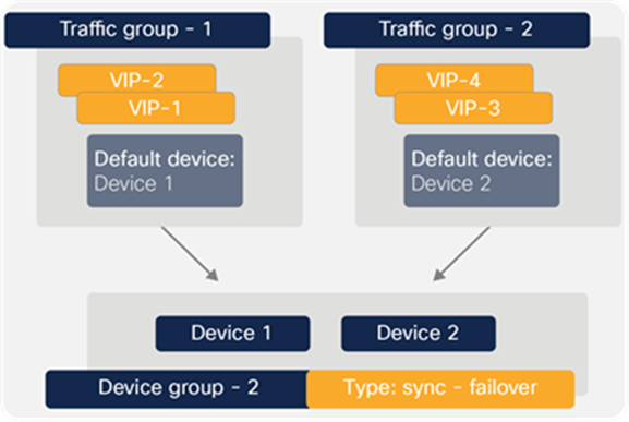
Device group with active/active configuration
By implementing this configuration, you ensure that:
● Any objects on a BIG-IP device that you configure for synchronization remain synchronized between the two devices
● Failover capability and connection mirroring are enabled on each device
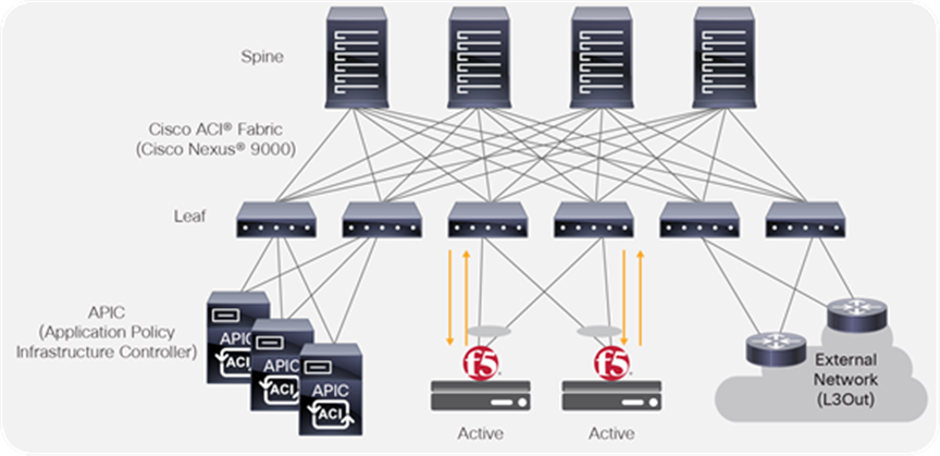
Active/active BIG-IP topology
Some considerations while deploying an active/active mode is that an active/active architecture can be helpful in the case of high load over an active/standby architecture. The drawback is that if you lose one of your devices, the other one may not be able to cope with complete traffic load. In terms of functionality, the LTM software module supports active/active mode, but other BIG-IP modules may not.
See the F5 Knowledge base for details: https://support.f5.com/csp/article/K15002
Note: For active/active mode, you must use network failover instead of hard-wired serial failover. These two types of failovers are discussed in the next section.
Failover
To enable a device to fail over to its peer device, you must first specify the type of failover that you want the redundant system to use.
The two possible failover types are hard-wired failover and network-based failover. Hard-wired failover is applicable to only active/standby configurations. However, network-based failover is applicable to both active/standby as well as active/active configurations.
Hard-wired failover
When you configure hard-wired failover, you enable failover by using a failover cable to physically connect the two redundant devices. This is the default setting.
Network failover
When you configure network failover, you enable failover by configuring your redundant system to use the network to determine the status of the active device. You can use network failover in addition to, or instead of, hard-wired failover.
On the BIG-IP, multiple interfaces can be used to decide if the network failover should occur. Configuring failover requires you to specify certain types of IP addresses on each device. Some of these IP addresses enable continual, High-Availability (HA) communication among devices in the device group, while other addresses ensure that application traffic processing continues when failover occurs.
The types of IP addresses on each BIG-IP device that can be used for network failover are:
● A local, static, self-IP address for VLAN ‘HA’. This unicast self-IP address is the main address that other devices in the device group use to communicate continually with the local device to assess the health of that device. When a device in the device group fails to receive a response from the local device, the BIG-IP system triggers failover.
● A local management IP address. This unicast management IP address serves the same purpose as the static self-IP address for VLAN ‘HA’, but it is only used when the local device is unreachable through the ‘HA’ static self-IP address.
In the case of using network failover for HA on the BIG-IP with ACI (Figure 22), if the network failover traffic is carried outside of the Cisco ACI fabric (for example, when using interfaces that are connected to each BIG-IP device directly) the Cisco ACI fabric doesn’t have to manage the failover network. If the network failover traffic is carried within the Cisco ACI fabric, an EPG will need to be configured for the failover traffic.
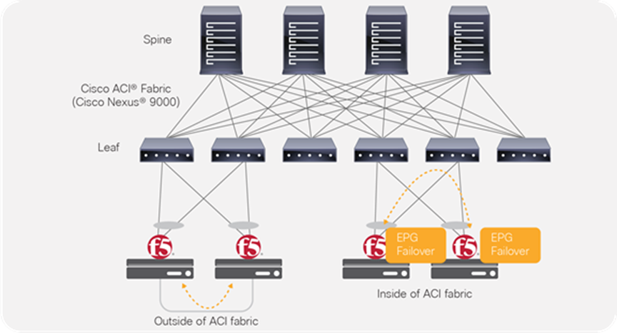
Failover network design option
For general BIG-IP HA considerations and configuration, refer to the following documents:
● HA recommendations – https://support.f5.com/csp/article/K14135
● Hardwired versus network-based failover – https://support.f5.com/csp/article/K2397
● Persistence and mirroring – https://support.f5.com/csp/article/K13478
Endpoint movements during failover
When failover takes place, the newly active BIG-IP sends Gratuitous Address Resolution Protocol (GARP) for floating self-IPs and VIPs. This is done so that endpoints and network devices in the same broadcast domain can update the ARP table and MAC address table. The ACI fabric has “Move Frequency (per second)” configuration in “Endpoint Retention Policy” that is referred from bridge domains to limit the maximum number of endpoint moves allowed per second in the bridge domain. The number is counted as total movements of any endpoint in the given bridge domain, whether it is a single endpoint flap, a simultaneous move of multiple endpoints, or a combination of both. If the number of movements per second is exceeded, the “Move Frequency” (256 by default) and the “Hold interval” (300 seconds by default) will trigger, and the learning new endpoint in the bridge domain is disabled until the “Hold Interval” expires. This feature is called BD Move Frequency or Endpoint Move Dampening. If there are many IP addresses in a bridge domain that are expected to move at the same time, for example BIG-IP owns many IPs in a given bridge domain, you might need to increase the “Move Frequency” to prevent endpoint learning from being disabled in the bridge domain. The APIC configuration location for “End Point Retention Policy” is at Tenant > Policies > Protocol > End Point Retention, which is referred from bridge domains.
The other option to prevent endpoint learning from being disabled in the bridge domain is to enable “Rogue EP Control”. If the Rogue EP Control is enabled, Endpoint Move Dampening via Endpoint Retention Policy explained above will not take effect. The APIC configuration location for “Rogue EP Control” is at System > System Settings > Endpoint Controls > Rogue EP Control. This configuration is a fabric-wide setting and is disabled by default.
For more details on ACI endpoint learning behavior and the configurations above, refer to “Endpoint Retention Policy” and “Rogue EP Control” sections in the ACI Fabric Endpoint Learning White Paper: https://www.cisco.com/c/en/us/solutions/collateral/data-center-virtualization/application-centric-infrastructure/white-paper-c11-739989.html.
Another scenario possible after BIG-IP failover takes place is that the new standby BIG-IP still sends traffic using floating self-IPs and VIPs as source IP addresses. This will result in the ACI fabric learning the IPs from multiple locations via the data plane. This issue can be avoided by disabling IP Data-plane Learning.
For more details on ACI IP Data-plane Learning and its use case, refer to “IP Data-plane Learning” section in the ACI Fabric Endpoint Learning White Paper: https://www.cisco.com/c/en/us/solutions/collateral/data-center-virtualization/application-centric-infrastructure/white-paper-c11-739989.html#IPDataplaneLearning
MAC masquerade
MAC masquerading is a feature that allows you to manually allocate a MAC address to a traffic group across a BIG-IP pair configured for high availability. More specifically, this MAC address floats between the devices in an HA pair, along with the floating self-IPs and virtual addresses within the same traffic group.
Highly recommend using MAC masquerade under the following conditions:
● To improve reliability and failover speed in lossy networks by minimizing Address Resolution Protocol (ARP) table updates on servers and network devices that are in the same broadcast domain with BIG-IP system.
● When using Policy-Based Redirect (PBR) on Cisco ACI
For more information and configuration, refer to SOL13502: Configuring MAC masquerade (11.x)
When configuring traffic-group MAC masquerading for BIG-IP Virtual Edition (VE) on VMware ESXi servers, you must configure the virtual switch's Forged Transmits and Promiscuous Mode settings to Accept. By default, the Promiscuous Mode and Forged Transmits settings are disabled. Since the VMM integration with the Cisco APIC, the port-group security settings are controlled by the APIC and cannot be changed directly on VMware vCenter or ESXi servers. The APIC settings for the port-group security settings are available at the domain association configuration under an EPG.
When using MAC masquerade with BIG-IP VE along with ACI Service Graph, enabling the ‘Promiscuous Mode setting’ at the logical device cluster configuration on the APIC is required.
To learn more about Layer 4 to Layer 7 services configuration, visit: https://www.cisco.com/c/en/us/support/cloud-systems-management/application-policy-infrastructure-controller-apic/tsd-products-support-series-home.html
Auto Last Hop (source MAC-based forwarding)
The Auto Last Hop setting allows the BIG-IP to track the source MAC address of incoming connections and return traffic from pools to the source MAC address, regardless of the routing table.
When enabled, Auto Last Hop allows the BIG-IP system to send return traffic from pools to the MAC address that transmitted the request, even if the routing table points to a different network or interface. As a result, the BIG-IP system can send return traffic to clients, even when there is no matching route. An example would be when the BIG-IP system does not have a default route configured and the client is located on a remote network. Additionally, Auto Last Hop is useful when the BIG-IP system is load-balancing transparent devices that do not modify the source IP address of the packet. Without the Auto Last Hop option enabled, the BIG-IP system may not return connections to the same transparent node, resulting in asymmetric routing.
For most network configurations, Auto Last Hop is enabled by default.
When configuring in an environment where you may be required to disable Auto Last Hop, you should consider the following factors:
● If the last hop is a set of redundant routers or firewalls that do not use a shared MAC address, you can configure a last hop pool for the virtual server instead of disabling Auto Last Hop. For more information, refer to: https://support.f5.com/csp/article/K2211.
● For BIG-IP system compatibility with Virtual Router Redundancy Protocol (VRRP) and Hot Standby Router Protocol (HSRP), refer to: https://support.f5.com/csp/article/K9487
For more details of Auto Last Hop, refer to: https://support.f5.com/csp/article/K13876
If ACI PBR is used and Auto Last Hop is enabled, “Source MAC Rewrite” might need to be enabled on ACI PBR. Otherwise, the BIG-IP will use the original source MAC address, instead of the ACI bridge domain MAC, as the destination MAC for return traffic, even if the next hop of the traffic should be the ACI bridge domain MAC. See the Cisco ACI PBR white paper for more detail: https://www.cisco.com/c/en/us/solutions/collateral/data-center-virtualization/application-centric-infrastructure/white-paper-c11-739971.html
Link Layer Discovery Protocol (LLDP)
Consider configuring LLDP on the BIG-IP device and the APIC for the interface between the BIG-IP and the ACI leaf nodes. LLDP provides the BIG-IP system with the ability to advertise its identity and capabilities to the ACI network. Once the ACI network has the information about the BIG-IP interface, integrations like the F5 ACI ServiceCenter (discussed later in this document) will be able to use this information to build out a topology map.
IP Aging on ACI
Because of the nature of load balancer that owns multiple IPs with a single MAC address, it is recommended to enable “IP Aging” on ACI. The APIC configuration location for IP Aging is at System > System Settings > IP Aging. The default setting is disabled.
If IP Aging is disabled, an endpoint might have unused IP addresses stuck on the same MAC address. For example, when VIPs are using the same MAC as the self-IP, when BIG-IP is added and then the VIP is deleted as shown in Figure 23, the ACI fabric keeps the entry for the VIP that was already deleted as long traffic is received from the MAC. It is because the ACI fabric sees the endpoint as all three components (the MAC, self-IP, and VIP). If traffic is received from any one of these components, the entries for all three will be kept active.
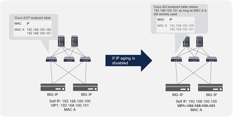
IP Aging policy use case
If IP Aging is enabled, the ACI fabric sends a unicast ARP packet at 75 percent of the configured endpoint retention timer for all IP addresses that belong to the endpoint. If no response is received from that particular IP address, it will be aged out of the endpoint table. (Note that the MAC address and responding IP address for the endpoint will be retained).
This section explains multi-tenant design examples and considerations on ACI and BIG-IP.
ACI multi-tenant design
This section explains the following ACI multi-tenant capabilities:
● Role-Based Access Control (RBAC) to create separate users for each tenant
● Network isolation for each tenant
● Security isolation for each tenant
● Allowing communication between tenants
A tenant in the ACI object model represents the highest level object. A tenant consists of networking-related objects such as VRFs, bridge domains and subnets, and policy-related objects such as application profiles, EPGs, and contracts, as shown in Figure 24. A tenant could be a unique customer, an operating group, a business device, an application, etc.
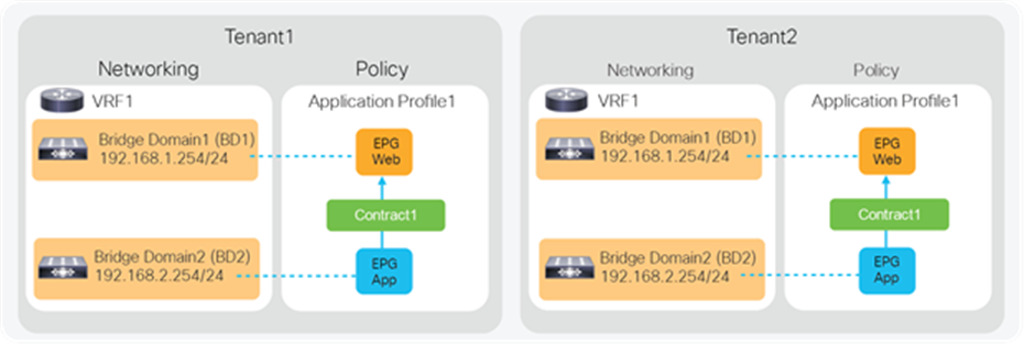
Cisco ACI tenant logical model
As of Release 4.2(3) of Cisco APIC, an ACI fabric supports up to 3000 tenants and 3000 VRFs. Refer to the ACI verified scalability guide for the latest status: https://www.cisco.com/c/en/us/support/cloud-systems-management/application-policy-infrastructure-controller-apic/tsd-products-support-series-home.html
Role-Based Access Control (RBAC)
By using ACI RBAC, an administrator can give tenant users access to their own tenant only. For example, User1 can write and read objects in Tenant1 only and User2 can write and read objects in Tenant2 only. Starting from APIC Release 5.0, the introduction of the Leaf RBAC feature allows an administrator to let users use specific leaf nodes only. For example, User1 for Tenant1 can use Leaf1 and Leaf2 only, and User2 for Tenant2 can use Leaf3 and Leaf4 only. This is useful for allocating isolated logical networks and physical resources to different purposes in a multi-tenant environment (see Figure 25).
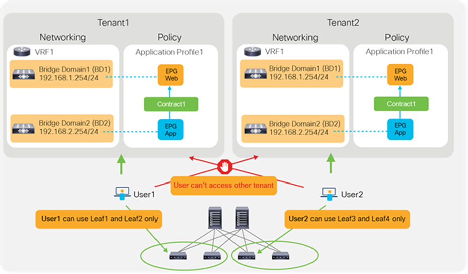
Cisco ACI RBAC for multi-tenancy
Network isolation
Objects such as VRFs, BDs, EPGs, and contracts defined in a tenant are not visible from other tenants unless objects are defined in a common tenant. Thus, the typical multi-tenant design is deployed so that each tenant has unique VRFs and BDs (Figure 26). The result is that EPGs in different tenants can’t be in the same network (VRF/BD), which means each tenant network is logically isolated, even though both VRFs are deployed in the same ACI fabric.
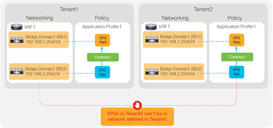
Use of unique VRFs and BDs provides network isolation
Security isolation
Another example is the use of VRFs/BDs defined in common (Figure 27). This allows EPGs in different tenants to be in the same network. However, they still can’t talk each other unless a contract is defined between them.
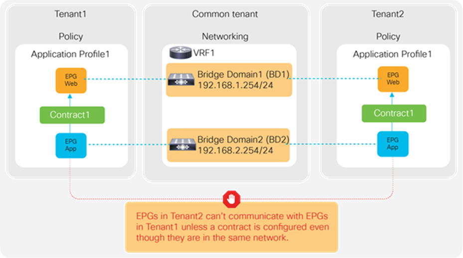
Use of common VRFs/BDs still provides security isolation
EPGs in different tenants can’t have a contract unless a contract is exported from the provider tenant to the consumer tenant, or a contract defined in a common tenant is used.
BIG-IP multi-tenant design
This section explains F5 BIG-IP multi-tenant design.
User role
A user role is a property of a BIG-IP administrative user account. For each BIG-IP user account, you can assign a different user role to each administrative partition to which the user has access. This allows you to assign multiple user roles to each user account on the system.
A user role controls:
● The types of resources that the user can manage. User roles define the types of resources, or objects, that a user can manage. For example, a user with the operator role can enable or disable nodes and pool members only. By contrast, a user with the guest role cannot manage any BIG-IP system resources.
● The tasks that a user can perform. For example, a user with the operator role can enable or disable nodes and pool members, but cannot create, modify, or delete them. Conversely, a user with the manager role can perform all tasks related to objects within a partition, except for tasks related to user accounts.
The BIG-IP system offers several different user roles that you can choose from when assigning roles to a user account. Each user role grants a different level and type of permissions to the user.
Note: You must have an administrator or user manager user role to assign user roles to a BIG-IP user account.
Administrative partitions
Ensure that specific users are granted access to only the partitions for which they are authorized. This is in addition to the role-based access that restricts users to specific operations. With administrative partitions, configuration objects are placed into specific partitions that only authorized users can access. While this design does have some limits in terms of the number of objects and partitions, it is quite capable of maintaining many hundreds of administrative partitions and route domains, making it a suitable candidate for larger-scale multi-tenancy.
Route domains
Route domains create strictly defined address spaces within a network. Each route domain contains IP address spaces, routing information, and VLANs. IP address spaces can be duplicated between domains, allowing easy reuse of RFC 1918 private addressing for multiple customers or projects. Route domains can be strictly isolated from one another or have explicitly controlled access between them. This allows a common “front-end” network space to be presented to an access network but with services running within dedicated “tenant” network spaces. Although system resources are not explicitly dedicated, each domain can be rate-limited by connections or throughput to provide some resource constraint. This design allows for the most efficient use of system resources since each domain will consume only the resources it allocated (see Figure 28).
To learn more about forwarding traffic between route domains, refer to: https://support.f5.com/csp/article/K84417414
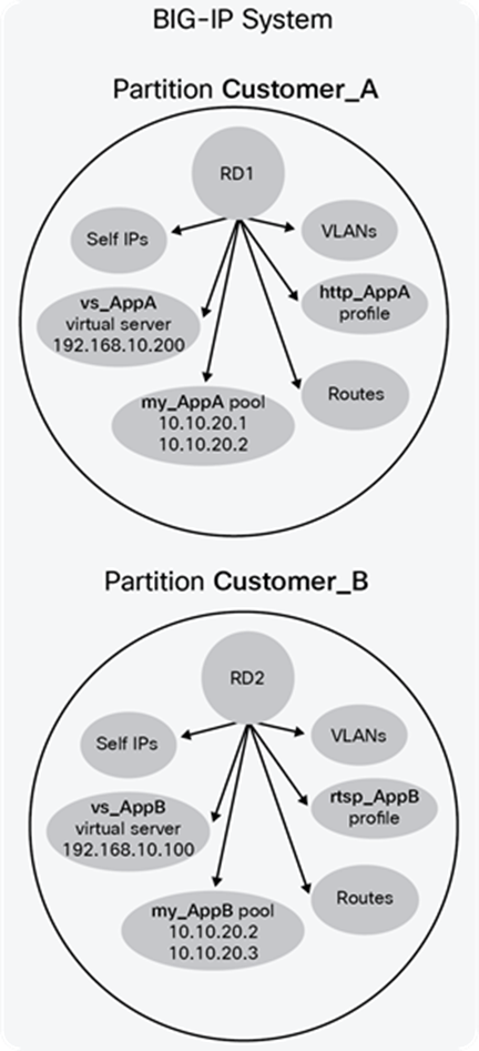
BIG-IP partition and Route Domain (RD) concept
Virtual Clustered Multiprocessing (vCMP)
Virtual Clustered Multiprocessing (vCMP) creates multiple isolated instances of the BIG-IP software on a single F5 hardware platform. Each instance has its own CPU, memory, and disk, and can take advantage of multiple assigned CPU cores using the same clustered multiprocessing design used on all F5 platforms. BIG-IP “guests” run on F5 vCMP-enabled hardware using a standards-based, purpose-built hypervisor that provides robust security and isolation.
vCMP is supported on VIPRION as well as BIG-IP appliances: https://support.f5.com/csp/article/K14088
A vCMP guest is an instance of the BIG-IP software that you create on the vCMP system for the purpose of provisioning one or more BIG-IP modules to process application traffic. A guest consists of a Traffic Management Operating System (TMOS) instance, plus one or more BIG-IP modules. Each guest has its own share of hardware resources that the vCMP host allocates to the guest, as well as its own management IP addresses, self-IP addresses, virtual servers, and so on. In this way, each guest effectively functions as its own multi-blade VIPRION cluster, configured to receive and process application traffic with no knowledge of other guests on the system. Furthermore, each guest can use TMOS features such as route domains and administrative partitions to create its own multi-tenant configuration. Each guest requires its own guest administrator to provision, configure, and manage BIG-IP modules within the guest. The maximum number of guests that a fully-populated chassis can support varies by chassis and blade platform. An example of a vCMP system is shown in Figure 29.
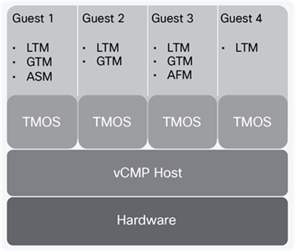
Example of a four-guest vCMP system
Refer to https://www.f5.com/services/resources/white-papers/multi-tenancy-designs-for-the-f5-high-performance-services-fabric on when to choose the right multi-tenancy design for BIG-IP based on different attributes.
ACI and BIG-IP multi-tenancy
Based on different considerations defined above for multi-tenancy, one way of combining the two technologies is to use a single BIG-IP for more than one ACI tenant (see Figure 30):
● A tenant on ACI is mapped to an administrative partition on the BIG-IP
● A VRF on ACI is mapped to a route domain within the partition on the BIG-IP
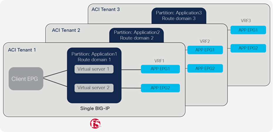
ACI and BIG-IP multi-tenancy mapping
Another method to achieve multi-tenancy, which includes appliance-based separation along with administrative and network separation, is to use a dedicated BIG-IP device per APIC tenant.
● A tenant on APIC can be mapped to a dedicated BIG-IP virtual edition or BIG-IP vCMP guest
● A VRF on ACI can be mapped to a route domain on a BIG-IP virtual edition or BIG-IP vCMP guest
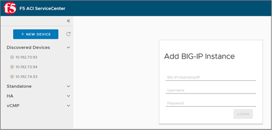
The F5 ACI ServiceCenter (Figure 31) is an application available to download from Cisco DC App Center, and runs on Cisco APIC. It is an integration point between the F5 BIG-IP and Cisco ACI. The application provides an APIC administrator—a unified way to manage both L2-L3 and L4-L7 infrastructure. Once day-0 activities are performed and BIG-IP is deployed within the ACI fabric using any of the design options already discussed, then the F5 ACI ServiceCenter can be used to handle day-1 and day-2 operations.
The day-1 and day-2 operations provided by the application are well suited for both new/greenfield and existing/brownfield deployments of BIG-IP and ACI deployments. The integration is loosely coupled, which allows the F5 ACI ServiceCenter to be installed or uninstalled with no disruption to traffic flow.
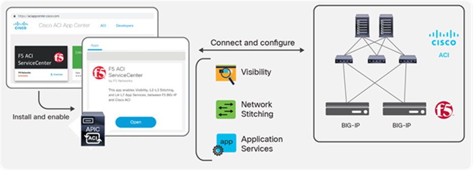
F5 ACI ServiceCenter
Features
Key features provided by the F5 ACI ServiceCenter are outlined below.
F5 ACI ServiceCenter has the ability to manage multiple BIG-IP devices
When the APIC is configured to use F5 BIG-IP within the Cisco ACI fabric as the L4-L7 device it does not have the ability to provide the BIG-IP credentials to the APIC. BIG-IP devices that are going to be managed by the F5 ACI ServiceCenter application have to be known to the F5 ACI ServiceCenter. There are two ways the BIG-IP devices can be known to the F5 ACI ServiceCenter. One way is by having the application user manually enter the BIG-IP device by providing the BIG-IP MGMT IP/hostname and credentials. The other way is by enabling LLDP on the interfaces between Cisco ACI and F5 BIG-IP. When enabling LLDP on the BIG-IP, include the BIG-IP management IP in the LLDP attributes list. The F5 ACI ServiceCenter will discover the BIG-IP using the BIG-IP chassis ID in the LLDP attribute list (Figure 32). Once discovered, the BIG-IP device will be added to the application by using the BIG-IP management IP. If the BIG-IP management IP is not available, the BIG-IP will be added using the BIG-IP serial number.
BIG-IP devices discovered using LLDP protocol along with management IP as part of LLDP attributes
Using the LLDP attributes the application will also be able to create a topology map (Figure 33).
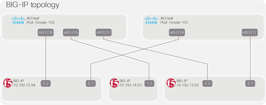
ACI and BIG-IP topology map
Once a device is added, either manually or using self-discovery via the LLDP protocol, the user will enter the BIG-IP credentials to log in and get started with managing the BIG-IP. The application will categorize the BIG-IP device into a standalone BIG-IP or a BIG-IP high availability cluster. The application can manage physical (appliance and vCMP) as well as virtual BIG-IP devices.
F5 ACI ServiceCenter has the capability to correlate BIG-IP and APIC information
A pool on the BIG-IP consists of a number of pool members. A pool member is a logical object that represents an application node. This application (endpoint) node is also discovered/learned by the APIC and is part of an endpoint group. Figure 34 illustrates this process.
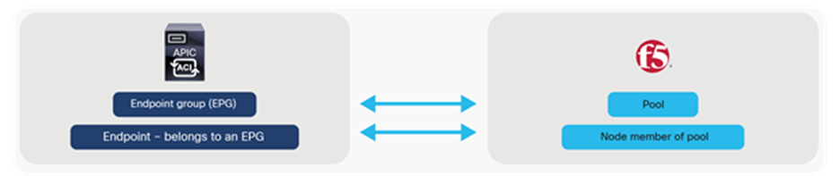
EPG to pool mapping
The F5 ACI ServiceCenter has ‘Read-only’ capabilities to the Cisco APIC and ‘Read-Write’ capabilities to the F5 BIG-IP. The application collects the BIG-IP network elements like VLANs, VIPs, pools, and nodes, and correlates them with APIC information like tenant, application profile, and EPGs (see Figure 35). The data that is visible through the application will be the BIG-IP nodes and pool members that are also learned by the APIC fabric. This feature will work for both new/greenfield and existing/brownfield deployments since, to the F5 ACI ServiceCenter, it does not matter how and when the data was configured on the BIG-IP, but instead, how the configured data relates to the APIC.
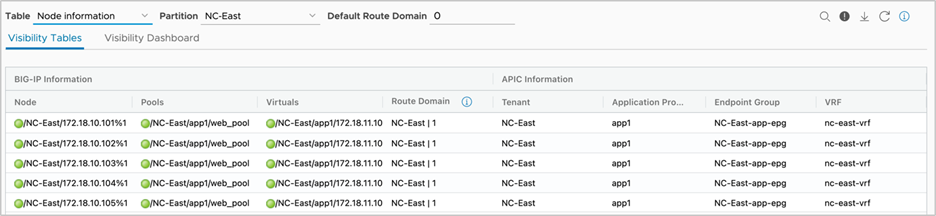
BIG-IP virtual IP, pool, and nodes correlated to the APIC tenant, application, profile and endpoint group
F5 ACI ServiceCenter has the capability to manage L2-L3 network configuration
The APIC administrator can manage L2-L3 configurations on the BIG-IP using the F5 ACI ServiceCenter. The configuration involves the ability to create, delete, and update operations for the VLAN, Self-IP, and default gateway on the BIG-IP.
The L2-L3 configuration is dependent on BIG-IP being inserted into the fabric using an APIC service graph. The VLANs from the APIC service graph are extracted by the application and then used to deploy the VLAN on the BIG-IP. The F5 ACI ServiceCenter user will have to supply the self-IPs and default gateway information and enter them in the application.
F5 ACI ServiceCenter has the capability to deploy L4-L7 application services
The application leverages the F5 Automation and Orchestration toolchain (a declarative API model) to deploy feature-rich applications (nodes, pools, VIPs, monitors, profiles, etc.) on the BIG-IP. The configuration on BIG-IP can be deployed using two methods. In the first method, the configuration API is completely exposed to the user and a configuration-compatible JSON payload is used to deploy the configuration. Figure 36 outlines the commands used to deploy the configuration.
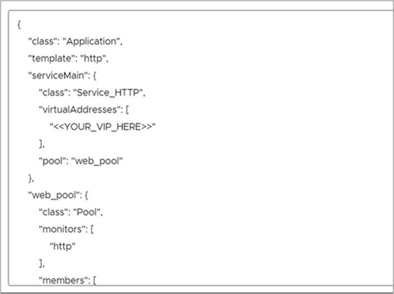
Advanced: BIG-IP application deployed using JSON payload
The second method is to make use of F5 Application Services Templates (FAST) embedded within the application (Figure 37). F5 Application Services 3 Extension (referred to as AS3 Extension or more often simply AS3) is a flexible, low-overhead mechanism for managing application-specific configurations on a BIG-IP system. AS3 uses a declarative model, meaning you provide a JSON declaration rather than a set of imperative commands. The declaration represents the configuration that AS3 is responsible for creating on a BIG-IP system.
The F5 Application Services Templates extension, or FAST, provides a toolset for templating and managing AS3 Applications on BIG-IP.
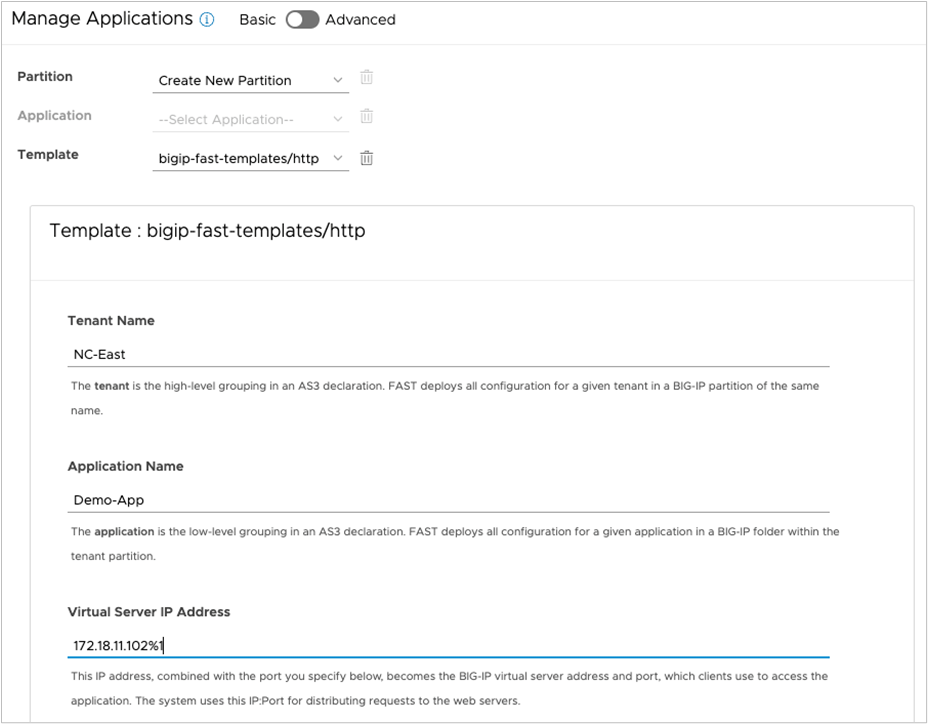
Basic: BIG-IP application deployed using FAST templates
F5 ACI ServiceCenter has the ability to dynamically add/remove pool members from the BIG-IP based on the endpoints discovered by APIC.
The application has the ability to adjust the pool members on the BIG-IP based on the server farm on the APIC. On the APIC, when workload is attached, it is learned by the fabric and added to a particular tenant, application profile, and EPG on the APIC. The F5 ACI ServiceCenter provides the capability to map an EPG on the APIC to a pool on the BIG-IP. The application relies on the attach/detach notifications from the APIC to add/delete the BIG-IP pool members (Figure 38). The pool members on BIG-IP are managed by the APIs provided by the F5 automation toolchain. The configuration (L4-L7 application deployment) on BIG-IP is recommended to be managed by the F5 ACI ServiceCenter in order to use this feature.
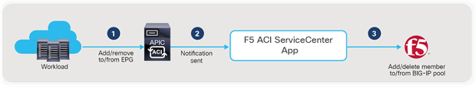
Add/delete pool member workflow
F5 ACI ServiceCenter supports multi-tenant design
Starting from version 2.11, F5 ACI ServiceCenter supports multi-tenant design using partition and route domain. Users can manage L2-L3 network configuration including the interface, self IP, default route and L4-L7 application services deployment in a specific route domain that resides in the common or a non-common partition.
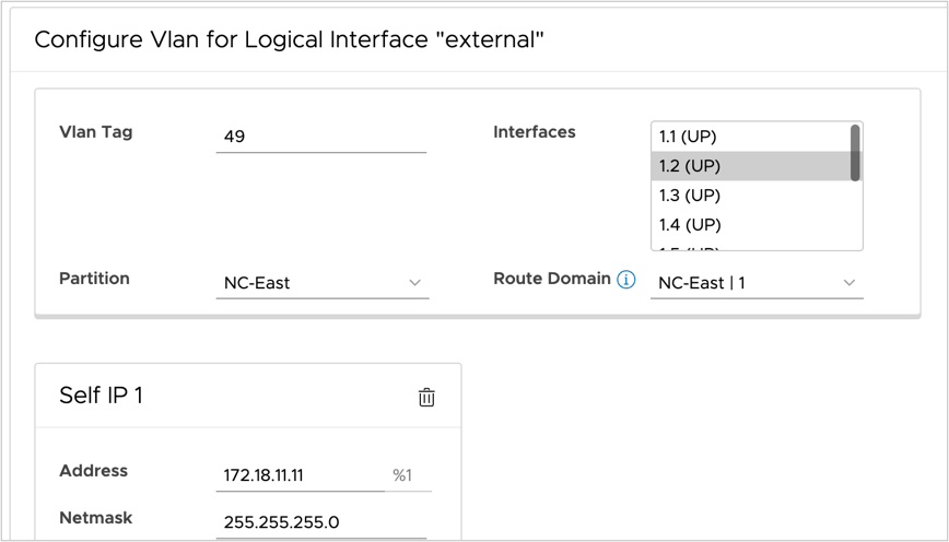
Interface and self IP configuration with partition and route domain
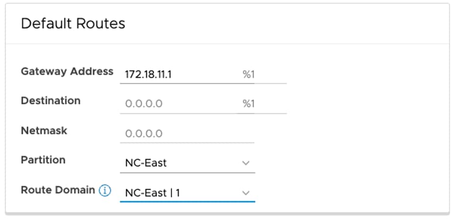
Default routes configuration with partition and route domain
ACI VRF to BIG-IP Route Domain mapping is added to the following locations too:
● Visibility tables and dashboards (Figure 35)
● Service discovery FAST templates in basic mode of L4-L7 application services (Figure 41)
● Endpoint mapping in advanced mode of L4-L7 application services (Figure 42)
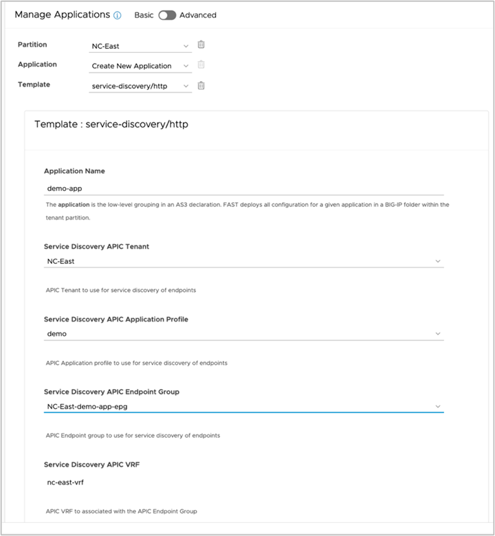
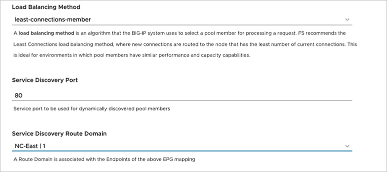
Service discovery FAST template with ACI VRF to BIG-IP route domain mapping (Basic mode)
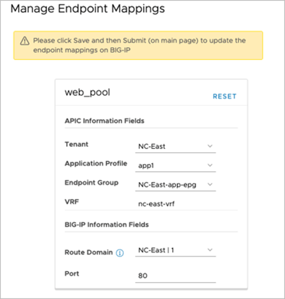
Manage Endpoint Mappings with ACI VRF to BIG-IP route domain mapping (Advanced mode)
Find more about the F5 ACI ServiceCenter
This section provides the resources for further information or to get you started.
Explore the solution
● Deployment and user guide: https://clouddocs.f5.com/f5-aci-servicecenter/latest/
● F5 and Cisco ACI Essentials - blog series: https://devcentral.f5.com/s/seriesarticlelist?id=aBy1T000000H5KwSAK
● Simplify BIG-IP & Cisco ACI Operations using Terraform –Webinar: https://www.youtube.com/watch?v=StsQqtxFFCk
Try the interactive demo and hands-on lab
● F5 ACI ServiceCenter - Lightboard Lesson video: https://www.youtube.com/watch?v=27cOoUIRWaY
● F5 ACI ServiceCenter - demo video: https://www.youtube.com/watch?v=BBOOixGIyhU
● F5 ACI ServiceCenter - interactive demo: https://simulator.f5.com/s/aci-service-center
● Cisco dCloud ACI ServiceCenter lab with “Getting Started” resources: https://dcloud.cisco.com/
Get Started
● Download software: https://dcappcenter.cisco.com/f5-aci-servicecenter.html
● Configuring F5 BIG-IP from APIC using Service Center App - Cisco Learning video: https://www.youtube.com/watch?v=zQCRck38TgE
● Cisco ACI and F5 BIG-IP Design Guide White Paper: https://www.cisco.com/c/en/us/solutions/collateral/data-center-virtualization/application-centric-infrastructure/white-paper-c11-743890.html
This section explains troubleshooting tips for the load balancer connected to the Cisco ACI fabric.
ACI troubleshooting
For ACI forwarding and policy troubleshooting, see the Cisco ACI Troubleshooting Guide for more details: https://www.cisco.com/c/dam/en/us/td/docs/switches/datacenter/aci/apic/sw/4-x/troubleshooting/Cisco_TroubleshootingApplicationCentricInfrastructureSecondEdition.pdf
The PBR section in the document includes a traffic flow example for the load balancer.
F5 troubleshooting
For F5 troubleshooting around various topics, visit:
https://support.f5.com/csp/article/K05939436
https://clouddocs.f5.com/training/community/f5cert/html/intro.html
Cisco ACI white papers: https://www.cisco.com/c/en/us/solutions/data-center-virtualization/application-centric-infrastructure/white-paper-listing.html