Cisco Application Centric Infrastructure K8s Design White Paper
Available Languages
Bias-Free Language
The documentation set for this product strives to use bias-free language. For the purposes of this documentation set, bias-free is defined as language that does not imply discrimination based on age, disability, gender, racial identity, ethnic identity, sexual orientation, socioeconomic status, and intersectionality. Exceptions may be present in the documentation due to language that is hardcoded in the user interfaces of the product software, language used based on RFP documentation, or language that is used by a referenced third-party product. Learn more about how Cisco is using Inclusive Language.
With the increasing adoption of container technologies and Cisco® Application Centric Infrastructure (Cisco ACI®) as a pervasive data-center fabric technology, it is only natural to see customers trying to integrate these two solutions.
At the time of writing, the most popular container orchestrator engine is Kubernetes (often abbreviated K8s). A key design choice every Kubernetes administrator must make when deploying a new cluster is selecting a network plugin. The network plugin is responsible for providing network connectivity, IP address management, and security policies to containerized workloads.
A series of network plugins is available for Kubernetes, with different transport protocols and/or features being offered. To browse the full list of network plugins supported by Kubernetes, follow this link: https://kubernetes.io/docs/concepts/cluster-administration/networking/#how-to-implement-the-kubernetes-networking-model.
Note: While Cisco offers a CNI (container network interface) plugin directly compatible and integrated with Cisco ACI, that is not covered in this document. In this white paper we will be discussing the current best practices for integrating Cisco ACI with the following CNI Plugins:
● Cilium
Calico supports two main network modes: direct container routing (no overlay transport protocol) or network overlay using VXLAN or IPinIP (default) encapsulations to exchange traffic between workloads. The direct routing approach means the underlying network is aware of the IP addresses used by workloads. Conversely, the overlay network approach means the underlying physical network is not aware of the workloads’ IP addresses. In that mode, the physical network only needs to provide IP connectivity between K8s nodes while container to container communications is handled by the Calico network plugin directly. This, however, comes at the cost of additional performance overhead as well as complexity in interconnecting your container-based workloads with external non-containerized workloads.
When the underlying networking fabric is aware of the workloads’ IP addresses, an overlay is not necessary. The fabric can directly route traffic between workloads inside and outside of the cluster as well as allowing direct access to the services running on the cluster. This is the preferred Calico mode of deployment when running on premises.[1] This guide details the recommended ACI configuration when deploying Calico in direct routing mode.
You can read more about Calico at https://docs.projectcalico.org/
The Kube-router is an open-source turnkey solution for Kubernetes networking that aims to provide operational simplicity. It supports two main network modes: direct container routing (there is no overlay transport protocol) or network overlay using PinIP (default) encapsulations to exchange traffic between workloads.
The same concepts discussed for Calico apply to the Kube-router, and this guide details the recommended Cisco ACI configuration when deploying Kube-router in BGP mode.
Cilium is an open-source project to provide networking, security, and observability for cloud-native environments such as Kubernetes clusters and other container orchestration platforms.
At the foundation of Cilium is a new Linux kernel technology called eBPF, which enables the dynamic insertion of powerful security, visibility, and networking control logic into the Linux kernel. eBPF is used to provide high-performance networking, multicluster and multicloud capabilities, advanced load balancing, transparent encryption, extensive network security capabilities, transparent observability, and much more.[2]
The same concepts discussed for Calico apply to Cilium, and this guide details the recommended Cisco ACI configuration when deploying Cilium in BGP mode.
In a K8s network, each compute server acts as a router for all the endpoints that are hosted on that compute server. We call that function a vRouter. The data path is provided by the Linux kernel, the control plane by a BGP protocol server, and management plane by the specific CNI plugin implementation.
Each endpoint can only communicate through its local vRouter. The first and last hop in any packet flow is an IP router hop through a vRouter. Each vRouter announces all the endpoints it is responsible for to all the other vRouters and other routers on the infrastructure fabric using BGP, usually with BGP route reflectors to increase scale.[3]
Calico proposes three BGP design options:
● The BGP AS Per Rack design
● The BGP AS Per Compute Server design
● The Downward Default design
They are all detailed at https://docs.projectcalico.org/reference/architecture/design/l3-interconnect-fabric
Kube-router, by default, places the cluster in the same AS (BGP per Cluster) and establishes an iBGP Full Node-To-Node Mesh.
Kube-router options are all detailed at https://github.com/cloudnativelabs/kube-router/blob/master/docs/bgp.md.
Cilium leaves the creation of the BGP topology up to the user and all the options are detailed at https://docs.cilium.io/en/stable/network/bgp-control-plane/
After taking into consideration the characteristics and capabilities of ACI, Calico, Cilium and Kube-router CNI Plugins, Cisco’s current recommendation is to implement an alternative design where a single AS is allocated through the whole cluster, and iBGP Full Node-To-Node Mesh is disabled for the cluster.
AS Per Cluster design – overview
In this design, a dedicated Cisco ACI L3Out is created for the entire Kubernetes cluster. This removes control-plane and data-plane overhead on the K8s cluster, thus providing improved performance and enhanced visibility to the workloads.
Each Kubernetes node has the same AS number and peers via eBGP with a pair of ACI Top-of-Rack (ToR) switches configured in a vPC pair. Having a vPC pair of leaf switches provides redundancy within the rack.
This eBGP design does not require running any route reflector nor full mesh peering (iBGP) in the K8s infrastructure; this results in a more scalable, simpler, and easier to maintain architecture.
In order to remove the need of running iBGP in the cluster the ACI BGP configuration requires the following features:
● AS override: The AS override function replaces the AS number from the originating router with the AS number of the sending BGP router in the AS Path of outbound routes.
● Disable Peer AS Check—Disables the peer autonomous number check.
With these two configuration options enabled, ACI advertises the POD Subnets between the Kubernetes nodes (even if learned from the same AS) ensuring all the PODs in the Cluster can communicate with each other.
An added benefits of configuring all the Kubernetes nodes with the same AS is that it allows us to use BGP Dynamic Neighbors by using the Cluster Subnet as BGP neighbors, greatly reducing the ACI config complexity.
Note: You need to ensure Kubernetes nodes are configured to peer only with the Border Leaves Switches in the same RACK.
Once this design is implemented, the following connectivity is expected:
● Pods running on the Kubernetes cluster can be directly accessed from inside ACI or outside through transit routing.
● Pod-to-pod and node-to-node connectivity happens over the same L3Out and external end point group (EPG).
● Exposed Services can be directly accessed from inside or outside ACI. Those services are load- balanced by ACI through ECMP 64-way provided by BGP.
Figure 1 shows an example of such a design with two racks and a six-node K8s cluster:
● Each rack has a pair of ToR leaf switches and three Kubernetes nodes.
● ACI uses AS 65002 for its leaf switches.
● The six Kubernetes nodes are allocated AS 65003:
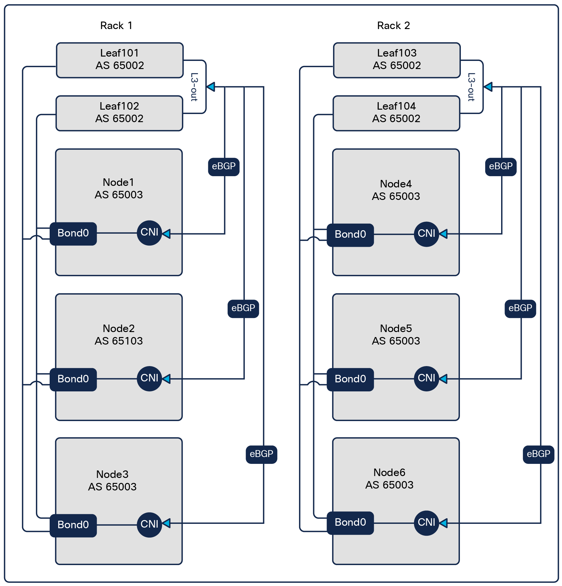
AS Per Cluster design
The physical connectivity is provided by a virtual Port-Channel (vPC) configured on the ACI leaf switches toward the Kubernetes nodes. One L3Out is configured on the ACI fabric to run eBGP with the vRouter in each Kubernetes node through the vPC port-channel.
The vPC design supports both virtualized and bare-metal servers.
When it comes to connecting the K8s nodes to the ACI fabric, an important decision to make is choosing to use standard SVIs or floating SVIs. If you are not familiar with floating SVI, you should take a moment to read https://www.cisco.com/c/en/us/td/docs/switches/datacenter/aci/apic/sw/kb/Cisco-ACI-Floating-L3Out.html
The following table should help you decide between the two options. The table is based on Cisco ACI Release 5.2.7 scale and features.
Table 1. Floating SVI vs Standard SVI
|
|
Floating SVI |
Standard SVI |
| Max cluster rack span[4] |
3 racks: 6 anchor nodes: with optimal traffic flows |
6: 12 Border Leaves with optimal traffic flows |
| Node subnets required |
One subnet for the whole cluster |
One /29 Subnet Per Node |
| Static paths binding |
None; the binding is done at the physical domain level. |
One per vPC |
| VM mobility |
Yes, with suboptimal traffic flows if the VMs move to a different rack |
No |
| Per fabric scale |
200 floating SVI IPs (An IPv4/6 dual stack cluster uses two floating SVIs.) |
Unlimited |
| L3Out per fabric |
100 |
2400 |
| ACI version |
5.0 or newer |
Any (This design was tested on 4.2 and 5.x code.) |
Note: Floating SVI L3Out and regular, or “standard,” SVI L3Out can coexist in the same ACI fabric and leaves.
Recommendation: Floating SVI is the better design choice, providing a simpler and more flexible configuration. As long as it can fulfil the scale requirements of your K8s environments, floating SVI is the preferred design choice.
The rest of the document will cover both the floating SVI and the regular or standard SVI approach. Since most of the configuration between the two options is identical, this document will first focus on the specific implementation details of a floating SVI, continue with the details of a standard SVI design, and end with the common configurations.
A detailed configuration example will be also provided for both options.
The floating SVI feature enables you to configure an L3Out without specifying logical interfaces. The feature saves you from having to configure multiple L3Out logical interfaces to maintain routing when Virtual Machines (VMs) move from one host to another. Floating SVI is supported for VMware vSphere Distributed Switch (VDS) as of ACI Release 4.2(1) and on physical domains as of ACI Release 5.0(1). It is recommended to use the physical domains approach for the following reasons:
● Can support any hypervisor
● Can support mixed mode clusters (VMs and bare metal)
Using floating SVI also relaxes the requirement of not having any Layer-2 communications between the routing nodes; this allows the design to use:
● A single subnet for the whole cluster
● A single encapsulation (VLAN) for the whole cluster
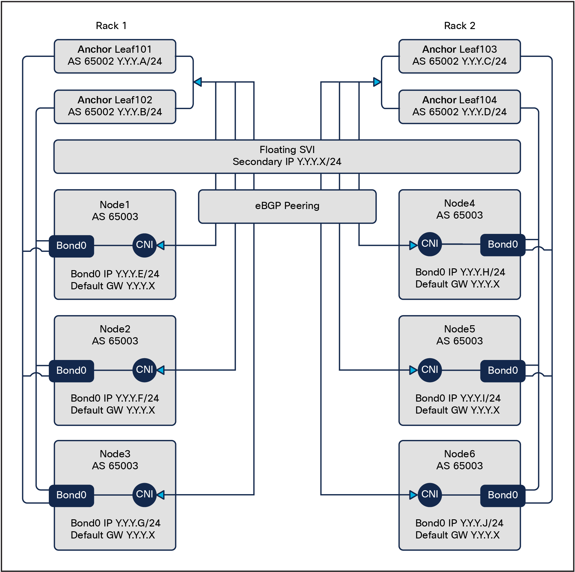
Floating SVI design
A requirement for this design is to peer the K8s node with directly attached anchor nodes: routes generated by nodes directly connected to the anchor nodes are preferred over routes from nodes not directly connected to the Anchor Nodes.
As show in Figure 3. Leaf101 will only install one ECMP path for 1.1.1.1/32 via 192.168.2.1 as the locally attached route is preferred.
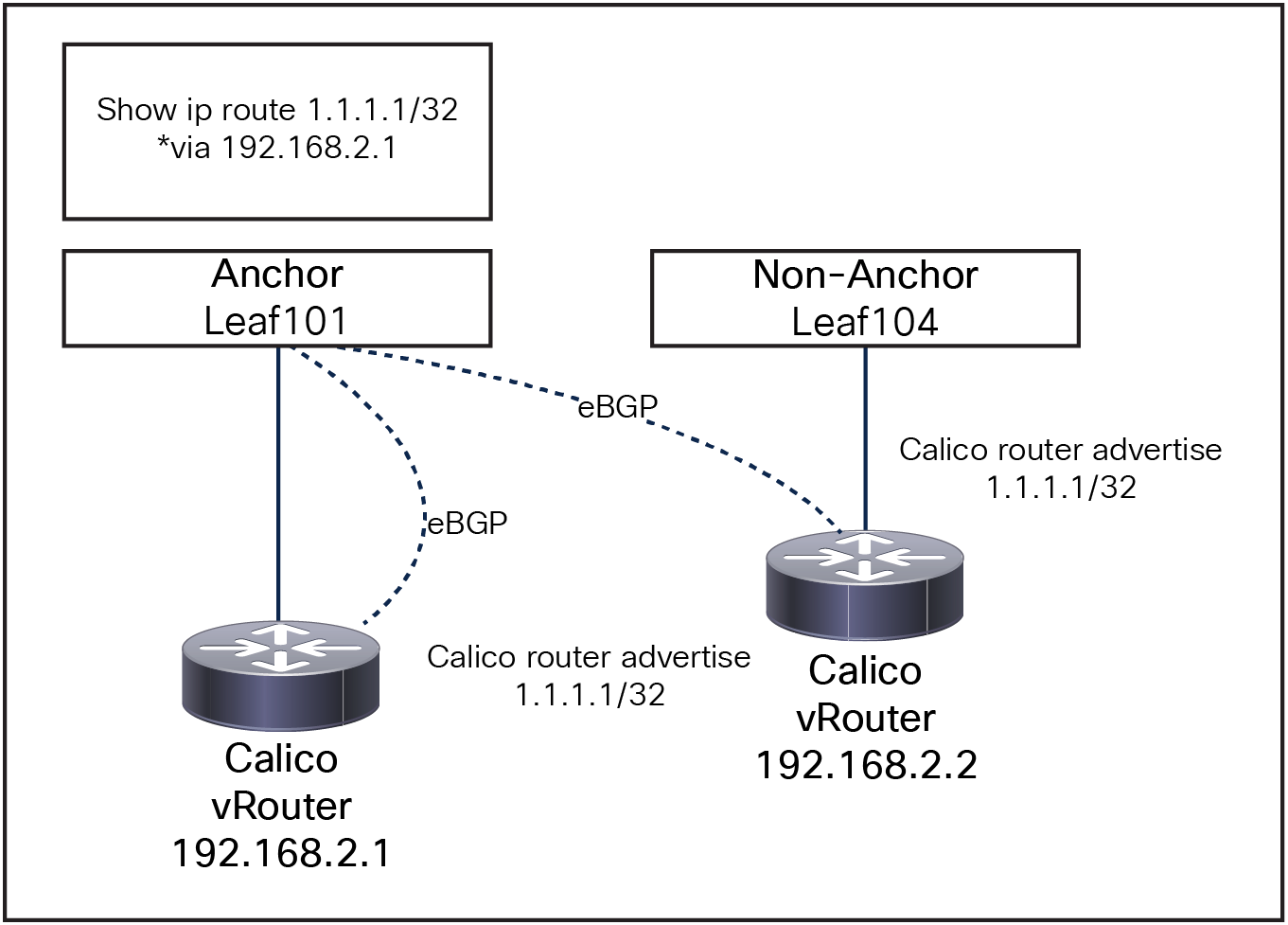
Floating SVI and Non-Directly attached nodes
If floating SVI cannot be used due to scale limitations or ACI version, a valid alternative is to use standard SVI. The high-level architecture is still the same, where the K8s nodes peer with the local (same rack) border leaves; however, a “standard” L3out is meant to attach routing devices only. It is not meant to attach servers directly on the SVI of an L3Out because the Layer 2 domain created by an L3Out with SVIs is not equivalent to a regular bridge domain.
For this reason, it is preferred not to have any Layer-2 switching between the K8s nodes connected to an external bridge domain.
To ensure that our cluster follows this design “best practice,” we will need to allocate:
● A /29 subnet for every server
● A dedicated encapsulation (VLAN) on a per-node basis
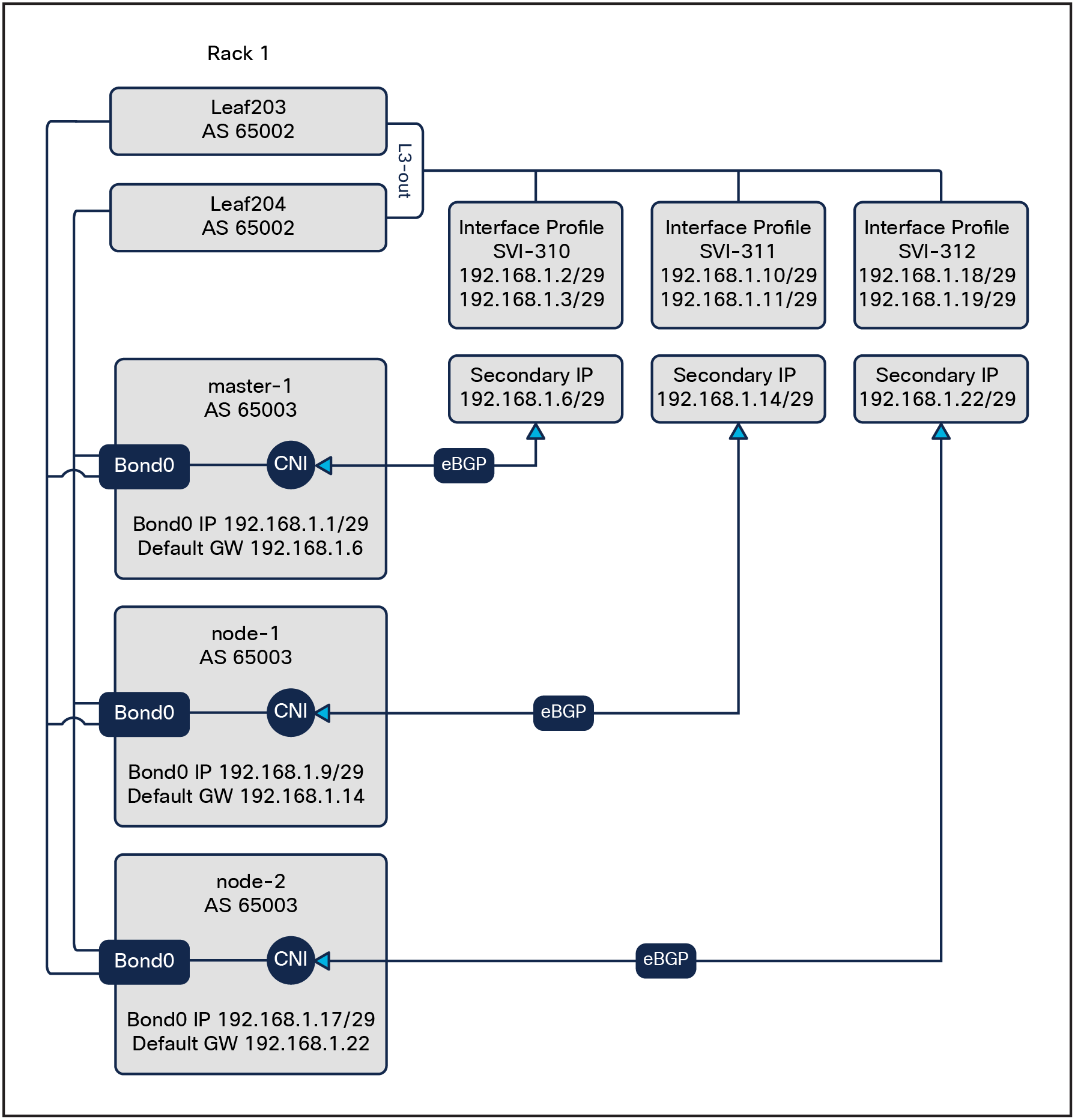
Standard SVI design
Each Kubernetes node uses ACI as default gateway (GW). The GW IP address is the secondary IP of the floating SVI or standard SVI interfaces.
If the Kubernetes nodes are Virtual Machines (VMs), follow these additional steps:
● Configure the virtual switch’s port-group load-balancing policy (or its equivalent) to “route based on IP address”
● Avoid running more than one Kubernetes node per hypervisor. It is technically possible to run multiple Kubernetes nodes on the same hypervisor, but this is not recommended because a hypervisor failure would result in a double (or more) Kubernetes node failure.
● For standard SVI design only: Ensure that each VM is hard-pinned to a hypervisor and ensure that no live migration of the VMs from one hypervisor to another can take place.
If the Kubernetes nodes are bare metal, follow these additional steps:
● Configure the physical NICs in an LACP bonding (often called 802.3ad mode).
This design choice allows creating nodes with a single interface, simplifying the routing management on the nodes; however, it is possible to create additional interfaces as needed.
Kubernetes node egress routing
Because ACI leaf switches are the default gateway for the Kubernetes nodes, in theory the nodes only require a default route that uses the ACI L3Out as the next hop both for node-to-node traffic and for node to outside world communications.
However, for ease of troubleshooting and visibility, the ACI fabric is configured to advertise back to the individual nodes the /26 pod subnets.[5]
Benefits of using the L3Out secondary IP as default gateway include:
● Zero impact during leaf reload or interface failures: the secondary IP and its MAC address are shared between the ACI leaves. In the event of one leaf failure, traffic seamlessly converges to the remaining leaf.
● No need for a dedicated management interface. The node remains reachable even before eBGP is configured.
Kubernetes node ingress routing
Each Kubernetes node is configured to advertise the following subnets to ACI:
● Node subnet
● Its allocated subnet(s) inside the pod supernet (a /26 by default[6])
● Host route (/32) for any pod on the node outside of the pod subnets allocated to the node
● The whole service subnet advertised from each node
● Host route for each exposed service (a /32 route in the service subnet) for each service endpoint configured with the externalTrafficPolicy: Local
The AS override function replaces the AS number from the originating router with the AS number of the sending BGP router in the AS Path of outbound routes.
Disables the peer autonomous number check.
Both ACI and Calico are configured by default to use BGP Graceful Restart. When a BGP speaker restarts its BGP process or when the BGP process crashes, neighbors will not discard the received paths from the speaker, ensuring that connectivity is not impacted as long as the data plane is still correctly programmed.
This feature ensures that, if the BGP process on the Kubernetes node restarts (CNI Calico BGP process upgrade/crash), no traffic is impacted. In the event of an ACI switch reload, the feature is not going to provide any benefit, because Kubernetes nodes are not receiving any routes from ACI.
The ACI BGP timers should be set to 1s/3s to ensure faster convergence
Note: There is currently an issue with Calico that results in the BGP session being reset randomly with 1s/3s timers. Relaxing the timers to 10s/30s will avoid this issue. This behavior only applies to Calico, Kube-Router is not affected.
By default, ACI only installs 16 eBGP/iBGP ECMP paths. This would limit spreading the load to up to 16 K8s nodes. The recommendation is to increase both values to 64. Increasing also the iBGP max path value to 64 ensures that the internal MP-BGP process is also installing additional paths.
To protect the ACI against potential Kubernetes BGP misconfigurations, the following settings are recommended:
● Enable BGP password authentication.
● Set the maximum AS limit to one:
a. Per the eBGP architecture, the AS path should always be one.
● Configure BGP import route control to accept only the expected subnets from the Kubernetes cluster:
a. Pod subnet
b. Node subnet
c. Service subnet
● (Optional) Set a limit on the number of received prefixes from the nodes.
Kubernetes node maintenance and failure
Before performing any maintenance or reloading a node, you should follow the standard Kubernetes best practice of draining the node. Draining a node ensures that all the pods present on that node are terminated first, then restarted on other nodes. For more info see: https://kubernetes.io/docs/tasks/administer-cluster/safely-drain-node/
While draining a node, the BGP process running on that node stops advertising the service addresses toward ACI, ensuring there is no impact on the traffic. Once the node has been drained, it is possible to perform maintenance on the node with no impact on traffic flows.
As of ACI Release 5.2, the scalability of this design is bounded by the following parameters:
A single L3Out can be composed of up to 12 border leaves or 6 anchor. Assuming an architecture with two leaf switches per node, this limits the scale to a maximum of six or three racks per Kubernetes cluster. Considering current rack server densities, this should not represent a significant limit for most deployments. Should a higher rack/server scale be desired, it is possible to spread a single cluster over multiple L3Outs. This requires an additional configuration that is not currently covered in this design guide. If you are interested in pursuing such a large-scale design, please reach out to Cisco Customer Experience (CX) and services for further network design assistance.
The routes that are learned by the border/anchor leaves through peering with external routers are sent to the spine switches. The spine switches act as route reflectors and distribute the external routes to all the leaf switches that have interfaces that belong to the same tenant. These routes are called Longest Prefix Match (LPM) and are placed in the leaf switch's forwarding table with the VTEP IP address of the remote leaf switch where the external router is connected.
In this design, every Kubernetes node advertises to the local border leaf its pod host routes (aggregated to /26 blocks when possible) and service subnets, plus host routes for each service with externalTrafficPolicy: Local. Currently, on ACI ToR switches of the -EX, -FX, and -FX2 hardware family, it is possible to change the amount of supported LPM entries using “scale profiles” as described in: https://www.cisco.com/c/en/us/td/docs/switches/datacenter/aci/apic/sw/kb/b_Cisco_APIC_Forwarding_Scale_Profile_Policy.html
In summary, depending on the selected profile, the design can support from 20,000 to 128,000 LPMs.
Detailed configurations – example
This section shows the required ACI and Calico steps to configure integration with floating SVI or standard SVI as shown in figures 2 and 4.
Note: It is assumed the reader is familiar with essential ACI concepts and the basic fabric configuration (interfaces, VLAN pools, external routed domain, AAEP) and that a tenant with the required VRF already exists.
Example floating SVI IP allocation
With floating SVI, the IP allocation scheme is extremely simple and consists in allocating a subnet big enough to contain as many host addresses as the number of required K8s nodes plus one host address for every anchor node, one floating address, and one secondary address.
Example standard SVI IP allocation
A possible IP allocation schema is shown below:
1. Allocate a supernet big enough to contain as many /29 subnets as nodes. For example, for a 32-nodes cluster, you could use a /24 subnet, a 64-nodes would use a /23 subnet, and so on.
2. For every /29 subnet
● Allocate the first usable IP to the node
● Allocate the last three usable IPs for the ACI border leaves:
I. Last IP minus 2 for the first leaf
II. Last IP minus 1 for the second leaf
III. Last IP for the secondary IP
ACI BGP configuration (ACI Release 5.2)
Note that because each K8s node acts as a BGP router, the nodes attach to the ACI fabric through an external routed domain instead of a regular physical domain. When configuring the interface policy groups and Attachable Access Entity Profiles (AAEP) for your nodes, bind them to that single external routed domain and physical domain. You will attach that routed domain to your L3Out in the next steps.
3. Create a new L3Out.
● Go to Tenant <Name> -> Networking, right click on “External Routed Network,” and create a new L3Out.
Configure the basic L3Out parameters:
◦ Name: <Your L3Out Name>
◦ VRF: <Your VRF Name>
◦ External Routed Domain: <Your External Routed Domain>
◦ Enable BGP.
Click Next.
Note: If you use floating SVI, follow the steps in point 4, OR, if you use standard SVI, follow the steps in point 5.
4. Configure floating SVI:
● Select “Floating SVI” as interface type.
● Domain Type: Physical
● Domain: <Your Domain>
● Floating Address: An IP in the node subnet
● VLAN: Select a valid VLAN ID
● MTU: Select the desired MTU; 9000 is the recommended value.
● Node: Add here all your anchor nodes:
● Node ID: Select your node
● Router ID: A valid IP address
● IPv4/6: Your node primary address
5. Configure SVI:
● Select “SVI” as interface type
● Select the Layer 2 interface type: You should be using vPC.
● Select the physical path.
● VLAN: Select a valid VLAN ID.
● MTU: Select the desired MTU; 9000 is the recommended value.
● Configure side A and side B:
● Node ID should be selected automatically, based on your path.
● Router ID: A valid IP address
● IPv4/6: Your node primary address
● If you need more than two border leaves, you will have to add them manually after the creation of the L3OUT:
● Go to the L3OUT -> Logical Node Profiles -> <Node Profile Name> -> Click on “+” to add nodes. Give the node a router ID.
● Go to the L3OUT -> Logical Node Profiles -> Logical Interface Profiles -> <Logical Interface Profiles Name> -> SVI -> Click on “+” to add new paths.
Click Next twice, skipping the Protocols section.
Create a new external EPG.
● Name: “default”
● Subnets:
Add all your subnets:
I. Node subnets (use the supernet in the SVI case)
II. Pod subnets
III. Cluster subnet
IV. External service subnet
● (Optional) If you need to perform any route leaking, you should add the required subnet scope options, such as Export Route Control Subnet. This is required if these subnets are to be advertised outside of ACI.
6. Floating SVI and SVI: Add a secondary address.
● For each anchor node or SVI path, add a IPv4 secondary address.
● Floating SVI: This is one address for the whole cluster, as per Figure 2.
● SVI: Each pair of border leaves have a dedicated secondary IP, as per Figure 4.
7. Enable Import Route Control Enforcement:
● Select your L3OUT -> Policy -> Route Control Enforcement -> Enabled Import
8. Set the BGP timers to 1s Keep Alive Interval and 3s Hold Interval, to align with the default configuration of the CNI and provide fast node-failure detection. We are also configuring the maximum AS limit to 1 and Graceful Restart, as discussed previously.
9. Note: Calico BIRD Component is unable to handle the 1s/3s timer: https://github.com/projectcalico/calico/issues/7086 relaxing the timers to 2s/6s seems to provide a stable environment
● Expand “Logical Node Profiles,” right click on the Logical Node Profile, and select “Create BGP Protocol Profile.”
● Click on the “BGP Timers” drop-down menu and select “Create BGP Timers Policy.”
● Name: <Name>
● Keep Alive Interval: 1s
● Hold Interval: 3s
● Maximum AS Limit: 1
● Graceful Restart Control: Enabled
● Press: Submit.
● Select the <Name> BGP timer policy.
● Press: Submit.
(Optional) Repeat Step 8 for all the remaining “Logical Node Profiles.”
◦ Note: The 1s/3s BGP timer policy already exists now; there is no need to re-create it.
10. In order to protect the ACI fabric from potential BGP prefix misconfigurations on the Kubernetes cluster, Import Route Control has been enabled in step 7. In this step, we are going to configure the required route map to allow only the node, pod cluster service subnet and external service subnet to be accepted by ACI.
● Expand your L3Out, right click on “Route map for import and export route control,” and select “Create Route Map for…”
● Name: From the drop-down menu, select “default-import” node.
● Note: Do not create a new one; select the pre-existing one, called “default-import.”
● Type: “Match Prefix and Routing Policy”
● Click on “+” to create a new context.
● Order: 0
● Name: <Name>
● Action: Permit
● Click on “+” to create a new “Associated Matched Rules.”
● From the drop-down menu, select “Create Match Rule for a Route Map.”
● Name: <Name>
● Click “+” on Match Prefix:
● IP: POD Subnet
● Aggregate: True
● Click Update.
● Repeat the above step for all the subnets that you want to accept.
● Click Submit.
● Ensure the selected Match Rule is the one we just created.
● Click OK.
● Click Submit.
It is possible to use the same steps (10) to configure what routes ACI will export by selecting the “default-export” option. It is recommended to configure the same subnets as in step 10.
11. Create max ECMP Policies:
● Go to Policies -> Protocol -> BGP -> BGP Address Family Context -> Create a new one and set:
● eBGP Max ECP to 64
● iBGP Max ECP to 64
● Leave the rest to the default.
12. Apply the ECMP Policies:
● Go to Networking -> VRFs -> Your VRF -> Click “+” on BGP Context Per Address Family:
● Type: IPv4 unicast address family
● Context: Your Context
13. (Optional) Create maximum number of prefixes to limit how many prefixes we can accept from a single K8s node.
● Go to Policies -> Protocol -> BGP -> BGP Peer Prefix -> Create a new one and set:
● Action: Reject
● Max Number of Prefixes: Choose a value aligned with your cluster requirements.
14. Configure the eBGP Peers: Each of your K8s nodes should peer with the two ToR leaves as shown in Figure 2, "Floating SVI design.”
● Select your L3OUT -> Logical Node Profiles -> <Node Profile> -> Logical Interface Profile
● Floating SVI: Double click on the anchor node -> Select “+” under the BGP Peer Connectivity Profile.
● SVI: Right click on the SVI Path -> Select Create BGP Peer Connectivity Profile
● Configure the BGP Peer:
● Peer Address: Calico Cluster Subnet
● Remote Autonomous System Number: Cluster AS
● BGP Controls:
I. AS Override
II. Disable Peer AS Check
● Password/Confirm Password: BGP password
● BGP Peer Prefix Policy: BGP peer prefix policy name
Repeat this step for all your Anchor nodes
Calico routing and BGP configuration
This section assumes that the basic Kubernetes node configurations have already been applied:
● The Kubernetes node network configuration is complete (that is, default route is configured to be the ACI L3Out secondary IP, and connectivity between the Kubernetes nodes is possible).
● Kubernetes is installed.
● Calico is installed with BGP enabled and no Overlay/NAT for the IPPool https://projectcalico.docs.tigera.io/getting-started/kubernetes/self-managed-onprem/onpremises#install-calico
Note: Tigera Recommends installing Calico using the operator
● No configuration has been applied.
Note: In the next examples, it is assumed that Calico and “calicoctl” have been installed. If you are using K8s as a datastore, you should add the following line to your shell environment configuration:
To install Calico with BGP enabled and no Overlay/NAT for the IPPool you can modify the calicoNetwork section in the custom-resources.yaml as following:
calicoNetwork:
# Note: The ipPools section cannot be modified post-install.
ipPools:
- blockSize: 26
cidr: 192.168.3.0/24
encapsulation: None
natOutgoing: Disabled
nodeSelector: all()
bgp: Enabled
Create your cluster BGPConfiguration: in this file we disable BGP full mesh between the K8s nodes and set the serviceClusterIPs and serviceExternalIPs subnets so that they can be advertised by eBGP. These subnets are the service and external service subnets in Kubernetes.
apiVersion: projectcalico.org/v3
kind: BGPConfiguration
metadata:
name: default
spec:
asNumber: 65003
logSeverityScreen: Info
nodeToNodeMeshEnabled: false
serviceClusterIPs:
- cidr: 192.168.8.0/22
serviceExternalIPs:
- cidr: 192.168.3.0/24
calico-master-1#./calicoctl apply -f BGPConfiguration.yaml
Create a secret to store the BGP password. We also need to add a Role and RoleBinding to ensure the calico-node ServiceAccount can access the Secret.
apiVersion: v1
kind: Secret
metadata:
name: bgp-secrets
namespace: kube-system
type: Opaque
stringData:
rr-password: 123Cisco123
---
apiVersion: rbac.authorization.k8s.io/v1
kind: Role
metadata:
name: secret-access
namespace: kube-system
rules:
- apiGroups: [""]
resources: ["secrets"]
resourceNames: ["bgp-secrets"]
verbs: ["watch", "list", "get"]
---
apiVersion: rbac.authorization.k8s.io/v1
kind: RoleBinding
metadata:
name: secret-access
namespace: kube-system
roleRef:
apiGroup: rbac.authorization.k8s.io
kind: Role
name: secret-access
subjects:
- kind: ServiceAccount
name: calico-node
namespace: kube-system
calico-master-1#kubectl apply -f BGPPassSecret.yaml
Calico BGP Peering: In order to simplify the peering configuration, it is recommended to label the K8s node with the rack_id. We can then use the rack_id label to select the K8s nodes when we configure the BGP peering in Calico. For example:
calico-master-1 kubectl label node master-1 rack_id=1
calico-master-1 kubectl label node master-2 rack_id=2
Now when we create the BGP peering configuration, we can do the following:
● Set the peerIP to the Leaf IP address for the BGP peering.
● Set the asNumber to the ACI BGP AS number.
● Set the nodeSelector equal to the rack where the ACI leaf is located.
● Set the password to the secret created previously.
With this configuration we will automatically select all the nodes in rack_id ==X and configure them to peer with the selected ACI leaf.
For example:
---
apiVersion: projectcalico.org/v3
kind: BGPPeer
metadata:
name: "201"
spec:
peerIP: "192.168.2.201"
asNumber: 65002
nodeSelector: rack_id == "1"
password:
secretKeyRef:
name: bgp-secrets
key: rr-password
---
apiVersion: projectcalico.org/v3
kind: BGPPeer
metadata:
name: "202"
spec:
peerIP: "192.168.2.202"
asNumber: 65002
nodeSelector: rack_id == "1"
password:
secretKeyRef:
name: bgp-secrets
key: rr-password
---
apiVersion: projectcalico.org/v3
kind: BGPPeer
metadata:
name: "203"
spec:
peerIP: "192.168.2.203"
asNumber: 65002
nodeSelector: rack_id == "2"
password:
secretKeyRef:
name: bgp-secrets
key: rr-password
---
apiVersion: projectcalico.org/v3
kind: BGPPeer
metadata:
name: "204"
spec:
peerIP: "192.168.2.204"
asNumber: 65002
nodeSelector: rack_id == "2"
password:
secretKeyRef:
name: bgp-secrets
key: rr-password
calico-master-1#./calicoctl apply -f BGPPeer.yaml
Verify that the configuration is applied.
cisco@calico-master-1:~$ calicoctl get bgppeer
NAME PEERIP NODE ASN
201 192.168.2.201 rack_id == "1" 65002
202 192.168.2.202 rack_id == "1" 65002
203 192.168.2.203 rack_id == "2" 65002
204 192.168.2.204 rack_id == "2" 65002
Verify that BGP peering is established:
● From the Kubernetes node:
cisco@calico-node-1:~$ sudo calicoctl node status
Calico process is running.
IPv4 BGP status
+---------------+---------------+-------+------------+-------------+
| PEER ADDRESS | PEER TYPE | STATE | SINCE | INFO |
+---------------+---------------+-------+------------+-------------+
| 192.168.2.201 | node specific | up | 2021-10-05 | Established |
| 192.168.2.202 | node specific | up | 02:09:14 | Established |
+---------------+---------------+-------+------------+-------------+
● From ACI:
fab2-apic1# fabric 203 show ip bgp summary vrf common:calico
----------------------------------------------------------------
Node 203 (Leaf203)
----------------------------------------------------------------
BGP summary information for VRF common:calico, address family IPv4 Unicast
BGP router identifier 1.1.4.203, local AS number 65002
BGP table version is 291, IPv4 Unicast config peers 4, capable peers 4
16 network entries and 29 paths using 3088 bytes of memory
BGP attribute entries [19/2736], BGP AS path entries [0/0]
BGP community entries [0/0], BGP clusterlist entries [6/24]
Neighbor V AS MsgRcvd MsgSent TblVer InQ OutQ Up/Down State/PfxRcd
192.168.1.1 4 65003 3694 3685 291 0 0 00:01:30 2
192.168.1.9 4 65003 3618 3612 291 0 0 00:00:10 2
192.168.1.17 4 65003 3626 3620 291 0 0 00:00:13 3
By default, Kubernetes service IPs and node ports are accessible through any node and will be load-balanced by kube-proxy across all the pods backing the service. To advertise a service directly from just the nodes hosting it (without kube-proxy load balancing), configure the service as “NodePort” and set the “externalTrafficPolicy” to “Local.” This will result in the /32 service IP being advertised to the fabric only by the nodes where the service is active.
apiVersion: v1
kind: Service
metadata:
name: frontend
labels:
app: guestbook
tier: frontend
spec:
# if your cluster supports it, uncomment the following to automatically create
# an external load-balanced IP for the frontend service.
# type: LoadBalancer
ports:
- port: 80
selector:
app: guestbook
tier: frontend
type: NodePort
externalTrafficPolicy: Local
Verify that ACI is receiving the correct routes:
◦ Every Calico node advertises a /26 subnet to ACI from the pod subnet.[7]
◦ Every exposed service should be advertised as a /32 host route. For example:
Connect to one of the ACI border leaves and check that we are receiving these subnets
# POD Subnets: A neat trick here is to use the supernet /16 in this example with the longer-prefixes option. In this output the 192.168.2.x IPs are my K8s nodes.
Leaf203# show ip route vrf common:calico 10.1.0.0/16 longer-prefixes
IP Route Table for VRF "common:calico"
'*' denotes best ucast next-hop
'**' denotes best mcast next-hop
'[x/y]' denotes [preference/metric]
'%<string>' in via output denotes VRF <string>
10.1.38.64/26, ubest/mbest: 1/0
*via 192.168.2.7%common:calico, [20/0], 12:16:10, bgp-65002, external, tag 65003
recursive next hop: 192.168.2.7/32%common:calico
10.1.39.0/26, ubest/mbest: 1/0
*via 192.168.2.1%common:calico, [20/0], 2d03h, bgp-65002, external, tag 65003
recursive next hop: 192.168.2.1/32%common:calico
10.1.133.192/26, ubest/mbest: 1/0
*via 192.168.2.5%common:calico, [20/0], 2d03h, bgp-65002, external, tag 65003
recursive next hop: 192.168.2.5/32%common:calico
10.1.183.0/26, ubest/mbest: 1/0
*via 192.168.2.9%common:calico, [20/0], 03:04:10, bgp-65002, external, tag 65003
recursive next hop: 192.168.2.9/32%common:calico
# Service Subnets: assuming you have a service configured with the externalTrafficPolicy: Local option it should be advertised:
In this example the 192.168.10.150 is advertised by 3 ndoes.
cisco@calico-master-1:~$ kubectl -n guestbook get svc frontend
NAME TYPE CLUSTER-IP EXTERNAL-IP PORT(S) AGE
frontend NodePort 192.168.10.150 <none> 80:30291/TCP 31s
This CLUSTER-IP is frontending 3 PODs:
kubectl -n guestbook get pod -o wide -l tier=frontend
NAME READY STATUS RESTARTS AGE IP NODE
frontend-d7f77b577-cvqp4 1/1 Running 0 90s 10.1.183.4 worker-6
frontend-d7f77b577-fhsv8 1/1 Running 0 90s 10.1.226.67 worker-1
frontend-d7f77b577-lv6vc 1/1 Running 0 90s 10.1.97.196 worker-3
These nodes are not all peering with the same leaves:
Leaf203# show ip route vrf common:calico 192.168.10.150
192.168.10.150/32, ubest/mbest: 1/0
*via 192.168.2.9%common:calico, [20/0], 00:16:04, bgp-65002, external, tag 65003
recursive next hop: 192.168.2.9/32%common:calico
Leaf201# show ip route vrf common:calico 192.168.10.150
192.168.10.150/32, ubest/mbest: 2/0
*via 192.168.2.4%common:calico, [20/0], 00:01:14, bgp-65002, external, tag 65003
recursive next hop: 192.168.2.4/32%common:calico
*via 192.168.2.6%common:calico, [20/0], 00:01:14, bgp-65002, external, tag 65003
recursive next hop: 192.168.2.6/32%common:calico
Kube-Router routing and BGP configuration
Due to: https://github.com/cloudnativelabs/kube-router/issues/1323 only Kube-Router v1.5.1 or above are supported for this design.
This section assumes that the basic Kubernetes node configurations have already been applied:
● The Kubernetes node network configuration is complete (that is, default route is configured to be the ACI L3Out secondary IP, and connectivity between the Kubernetes nodes is possible).
● Kubernetes is installed.
● Kube-Router has not yet been deployed
When deploying Kube-Router the Daemonset args should be set following:
● Set the cluster global BGP Autonomous System
● Enable the advertisement of the external-ip, loadbalancer-ip and pod-cidr
● Disable: iBGP, IP-in-IP Overlay and Pod Egress NAT
● Override the next hop to the Node IP
These settings are going to be applied to all the kube-routers pods
Below is an example of the expected configuration parameter to add to the default kube-router config:
- --cluster-asn=<AS>
- --advertise-external-ip
- --advertise-loadbalancer-ip
- --advertise-pod-cidr=true
- --enable-ibgp=false
- --enable-overlay=false
- --enable-pod-egress=false
- --override-nexthop=true
The next steps consist in annotating the K8s nodes with the following annotations:
● kube-router.io/peer.ips: comma separated list of the IP of the ACI Leaves to peer with.
● kube-router.io/peer.asns: comma separated list of the AS numbers of the Leaves (one per leaf)
● kube-router.io/peer.passwords: comma separated list of the BGP Password the Leaves (one per leaf)
For example, to peer with leaf 101 and 102, in AS 65002 with BGP Password of “123Cisco123” the following annotation can be used:
kube-router.io/peer.ips=192.168.43.101,192.168.43.102
kube-router.io/peer.asns=65002,65002
kube-router.io/peer.passwords=MTIzQ2lzY28xMjM=,MTIzQ2lzY28xMjM=
To apply the annotation, you can use the following command:
kubectl annotate nodes master-1 kube-router.io/peer.ips=192.168.43.101,192.168.43.102
Note: Kube-Router reads/updates the annotation value only at startup time. If you deploy kube-router and then annotate the nodes, you will have to restart all the kube-router pods with the following command:
kubectl -n kube-system delete pod -l k8s-app=kube-router
Once the annotations are applied to all the nodes you can connect to any of the kube-router pods to see a snapshot of the current config and state:
master-1:~$ kubectl -n kube-system exec -it kube-router-7gxfr -- bash
Welcome to kube-router on "gitaction-nkt-master-3"!
Here's a quick look at what's happening on this Node
--- BGP Server Configuration ---
AS: 65003
Router-ID: 192.168.43.3
Listening Port: 179, Addresses: 192.168.43.3, ::1
--- BGP Neighbors ---
Peer AS Up/Down State |#Received Accepted
192.168.43.101 65002 1d 03:37:26 Establ | 8 8
192.168.43.102 65002 1d 03:37:24 Establ | 8 8
--- BGP Route Info ---
Network Next Hop AS_PATH Age Attrs
*> 192.168.44.0/28 192.168.43.1 65002 65002 1d 03:37:26 [{Origin: i}]
* 192.168.44.0/28 192.168.43.1 65002 65002 1d 03:37:24 [{Origin: i}]
*> 192.168.44.16/28 192.168.43.2 65002 65002 1d 03:37:26 [{Origin: i}]
* 192.168.44.16/28 192.168.43.2 65002 65002 1d 03:37:24 [{Origin: i}]
*> 192.168.44.32/28 192.168.43.3 00:01:03 [{Origin: i}]
*> 192.168.44.48/28 192.168.43.5 65002 65002 1d 03:37:26 [{Origin: i}]
* 192.168.44.48/28 192.168.43.5 65002 65002 1d 03:37:24 [{Origin: i}]
*> 192.168.44.64/28 192.168.43.4 65002 65002 1d 03:37:26 [{Origin: i}]
* 192.168.44.64/28 192.168.43.4 65002 65002 1d 03:37:24 [{Origin: i}]
*> 192.168.44.80/28 192.168.43.8 65002 65002 1d 03:37:26 [{Origin: i}]
* 192.168.44.80/28 192.168.43.8 65002 65002 1d 03:37:24 [{Origin: i}]
*> 192.168.44.96/28 192.168.43.101 65002 65002 1d 03:37:26 [{Origin: i}]
* 192.168.44.96/28 192.168.43.102 65002 65002 1d 03:37:24 [{Origin: i}]
*> 192.168.44.112/28 192.168.43.6 65002 65002 1d 03:37:24 [{Origin: i}]
* 192.168.44.112/28 192.168.43.6 65002 65002 1d 03:37:21 [{Origin: i}]
*> 192.168.44.128/28 192.168.43.9 65002 65002 1d 03:37:26 [{Origin: i}]
* 192.168.44.128/28 192.168.43.9 65002 65002 1d 03:37:24 [{Origin: i}]
*> 192.168.46.4/32 192.168.43.3 00:01:03 [{Origin: i}]
For the ACI checks, you can refer to the relevant section in the Calico example. The same commands can be re-used.
Cilium routing and BGP configuration
This section assumes that the basic Kubernetes node configurations have already been applied:
● The Kubernetes node network configuration is complete (that is, the default route is configured to be the ACI L3Out secondary IP, and connectivity between the Kubernetes nodes is possible).
● Kubernetes is installed.
● Cilium has not yet been deployed.
Current limitations:
● Lack of support for BGP MD5 Password Authentication. See https://github.com/cilium/cilium/issues/23052.
● Lack of support for externalTrafficPolicy: Local. An exposed service will be advertised through BGP by all the K8s nodes regardless of whether or not a POD exposed by the service is running on them. This results in suboptimal traffic flows. See https://github.com/cilium/cilium/issues/23035. At the time of writing, this feature has been implemented in Cilium Version 1.14.0-snapshot.4 (and above) and is working as expected.
Both of these issues, at the time of writing, are being worked on.
Cilium can be installed in different ways; in the example below, Helm is used.
helm repo add cilium https://helm.cilium.io/
helm repo update
(Optional) Install the Cilium CLI:[8]
CILIUM_CLI_VERSION=$(curl -s https://raw.githubusercontent.com/cilium/cilium-cli/master/stable.txt)
CLI_ARCH=amd64
if [ "$(uname -m)" = "aarch64" ]; then CLI_ARCH=arm64; fi
curl -L --fail --remote-name-all https://github.com/cilium/cilium-cli/releases/download/${CILIUM_CLI_VERSION}/cilium-linux-${CLI_ARCH}.tar.gz{,.sha256sum}
sha256sum --check cilium-linux-${CLI_ARCH}.tar.gz.sha256sum
sudo tar xzvfC cilium-linux-${CLI_ARCH}.tar.gz /usr/local/bin
rm cilium-linux-${CLI_ARCH}.tar.gz{,.sha256sum}
Once the Helm repo is ready, it is possible to use a values.yaml file to set the required install parameters.
Note: The configuration below is an example of how to integrate Cilium with ACI using eBGP and will need to be adapted to your production needs.
bgpControlPlane:
enabled: true
# -- Configure BGP
bgp:
# -- Enable BGP support inside Cilium; embeds a new ConfigMap for BGP inside
# cilium-agent and cilium-operator
enabled: true
announce:
# -- Enable allocation and announcement of service LoadBalancer IPs
loadbalancerIP: true
# -- Enable announcement of node pod CIDR
podCIDR: true
ipam:
mode: "cluster-pool"
operator:
clusterPoolIPv4PodCIDRList: ["192.168.19.0/24"]
clusterPoolIPv4MaskSize: 27
ipv4:
enabled: true
ipv6:
enabled: false
loadBalancer:
algorithm: maglev
operator:
replicas: 1
# Disable the encapsulation, enable routing for the node subnets
# and turn off NAT for everything
tunnel: disabled
enable-endpoint-routes: true
enableIPv6Masquerade: false
enableIPv4Masquerade: false
#Disable Kube Proxy
kubeProxyReplacement: "strict"
k8sServiceHost: 192.168.18.252
k8sServicePort: 8443
hubble:
# -- Enable Hubble (true by default).
enabled: true
relay:
# -- Enable Hubble Relay (requires hubble.enabled=true)
enabled: true
ui:
# -- Whether to enable the Hubble UI.
enabled: true
service:
# --- The type of service used for Hubble UI access, either ClusterIP or NodePort.
type: LoadBalancer
# Disable TLS, this is ok only for labs.
tls:
enabled: false
Create a CiliumLoadBalancerIPPool to define the IP pool for the LoadBalancer Services:
apiVersion: "cilium.io/v2alpha1"
kind: CiliumLoadBalancerIPPool
metadata:
name: "lb-pool"
spec:
cidrs:
- cidr: 192.168.21.0/24
Create a CiliumBGPPeeringPolicy (you will need one policy per rack). This policy defines:
◦ Which nodes are located in which rack through the nodeSelector
◦ The ASNs of the nodes
◦ Which services should be advertised through BGP (In the config below, all the services are exported by matching on a nonexistent key.)
◦ Which ACI leaves you are peering to, and their ASNs.
apiVersion: cilium.io/v2alpha1
kind: CiliumBGPPeeringPolicy
metadata:
name: rack-1
namespace: kube-system
spec:
nodeSelector:
matchLabels:
rack_id: "1"
virtualRouters:
- localASN: 65003
exportPodCIDR: true
serviceSelector:
matchExpressions:
- key: CiliumAdvertiseAllServices
operator: DoesNotExist
neighbors:
- peerAddress: "192.168.18.203/32"
peerASN: 65002
- peerAddress: "192.168.18.204/32"
peerASN: 65002
Annotate the node with the RackID:
kubectl label node pi-k8s-1 rack_id=1
kubectl label node pi-k8s-2 rack_id=2
kubectl label node pi-k8s-3 rack_id=3
Once the configuration is applied, it is possible to check the status of the BGP peering with the Cilium CLI utility:
cilium bgp peers
Node Local AS Peer AS Peer Address Session State Uptime Family Received Advertised
pi-k8s-1 65003 65002 192.168.18.203 established 27m17s ipv4/unicast 2 6
ipv6/unicast 0 0
65003 65002 192.168.18.204 established 27m14s ipv4/unicast 2 6
ipv6/unicast 0 0
pi-k8s-2 65003 65002 192.168.18.203 established 27m44s ipv4/unicast 2 6
ipv6/unicast 0 0
65003 65002 192.168.18.204 established 27m46s ipv4/unicast 2 6
ipv6/unicast 0 0
pi-k8s-3 65003 65002 192.168.18.203 established 27m4s ipv4/unicast 2 6
ipv6/unicast 0 0
65003 65002 192.168.18.204 established 27m6s ipv4/unicast 2 6
ipv6/unicast 0 0
● From ACI:
fab2-apic1# fabric 203 show ip bgp summary vrf rpi-k8s:vrf
----------------------------------------------------------------
Node 203 (Leaf203)
----------------------------------------------------------------
BGP summary information for VRF rpi-k8s:vrf, address family IPv4 Unicast
BGP router identifier 1.1.1.203, local AS number 65002
BGP table version is 274, IPv4 Unicast config peers 4, capable peers 3
10 network entries and 30 paths using 2828 bytes of memory
BGP attribute entries [6/1248], BGP AS path entries [0/0]
BGP community entries [0/0], BGP clusterlist entries [6/24]
Neighbor V AS MsgRcvd MsgSent TblVer InQ OutQ Up/Down State/PfxRcd
192.168.18.1 4 65003 1952 1951 274 0 0 00:32:29 6
192.168.18.2 4 65003 2626 2617 274 0 0 00:32:57 6
192.168.18.3 4 65003 2637 2631 274 0 0 00:32:17 6
To expose a service with Cilium through BGP, it is sufficient simply to create the service as type “LoadBalancer.” Remember that, due to https://github.com/cilium/cilium/issues/23035, the service IP will be advertised by all nodes.
apiVersion: v1
kind: Service
metadata:
name: frontend
labels:
app: guestbook
tier: frontend
spec:
# if your cluster supports it, uncomment the following to automatically create
# an external load-balanced IP for the frontend service.
# type: LoadBalancer
ports:
- port: 80
selector:
app: guestbook
tier: frontend
type: LoadBalancer
Verify that ACI is receiving the correct routes:
◦ Every Cilium node advertises a /27 subnet to ACI from the pod subnet.
◦ Every exposed service is advertised as a /32 host route. For example:
Connect to one of the ACI border leaves and check that we are receiving these subnets
# POD Subnets: A neat trick here is to use the supernet /16 in this example with the longer-prefixes option. In this output the 192.168.2.x IPs are my K8s nodes.
Leaf203# show ip route vrf rpi-k8s:vrf 192.168.19.0/24 longer-prefixes
192.168.19.0/27, ubest/mbest: 1/0
*via 192.168.18.2%rpi-k8s:vrf, [20/0], 00:58:02, bgp-65002, external, tag 65003
recursive next hop: 192.168.18.2/32%rpi-k8s:vrf
192.168.19.32/27, ubest/mbest: 1/0
*via 192.168.18.1%rpi-k8s:vrf, [20/0], 00:57:34, bgp-65002, external, tag 65003
recursive next hop: 192.168.18.1/32%rpi-k8s:vrf
192.168.19.64/27, ubest/mbest: 1/0
*via 192.168.18.3%rpi-k8s:vrf, [20/0], 00:57:21, bgp-65002, external, tag 65003
recursive next hop: 192.168.18.3/32%rpi-k8s:vrf
# Service Subnets: assuming you have a service configured it should be advertised:
In this example the 192.168.21.186 is advertised by 3 nodes.
pi@pi-k8s-1:~$ kubectl -n gb get svc frontend
NAME TYPE CLUSTER-IP EXTERNAL-IP PORT(S) AGE
frontend LoadBalancer 192.168.20.51 192.168.21.186 80:31569/TCP 69m
Leaf203# show ip route vrf rpi-k8s:vrf 192.168.21.186
IP Route Table for VRF "rpi-k8s:vrf"
'*' denotes best ucast next-hop
'**' denotes best mcast next-hop
'[x/y]' denotes [preference/metric]
'%<string>' in via output denotes VRF <string>
192.168.21.186/32, ubest/mbest: 3/0
*via 192.168.18.3%rpi-k8s:vrf, [20/0], 00:58:31, bgp-65002, external, tag 65003
recursive next hop: 192.168.18.3/32%rpi-k8s:vrf
*via 192.168.18.1%rpi-k8s:vrf, [20/0], 00:58:44, bgp-65002, external, tag 65003
recursive next hop: 192.168.18.1/32%rpi-k8s:vrf
*via 192.168.18.2%rpi-k8s:vrf, [20/0], 00:59:12, bgp-65002, external, tag 65003
recursive next hop: 192.168.18.2/32%rpi-k8s:vrf
Cluster connectivity outside of the fabric – transit routing
For nodes of the Kubernetes cluster to communicate with devices located outside the fabric, transit routing needs to be configured between the Calico L3Out and one (or more) L3Outs connecting to an external routed domain.
This configuration requires adding the required consumed/provided contracts between the external EPGs. Please refer to https://www.cisco.com/c/en/us/td/docs/dcn/whitepapers/cisco-application-centric-infrastructure-design-guide.html#Transitrouting for best practices on how to configure transit routing in Cisco ACI.
Cluster connectivity inside the fabric
Once the eBGP configuration is completed, pods and service IPs will be advertised to the ACI fabric. To provide connectivity between the cluster’s L3Out external EPG and a different EPG, all that is required is a contract between those EPGs.
IPv6 and Dual stack considerations
Cisco ACI supports both IPv4, IPv6 or Dual Stack designs.
Calico support IPv4/IPv6 Only and Dual Stack
Kube-Router support IPv4, IPv6 and Dual Stack is under development, see https://github.com/cloudnativelabs/kube-router/issues/307
Following this design guide, a network administrator would be capable to easily verify the status of the K8s cluster.
Under the L3Out logical interface profile, it is possible to visualize the BGP neighbors configured as shown in the following figure:
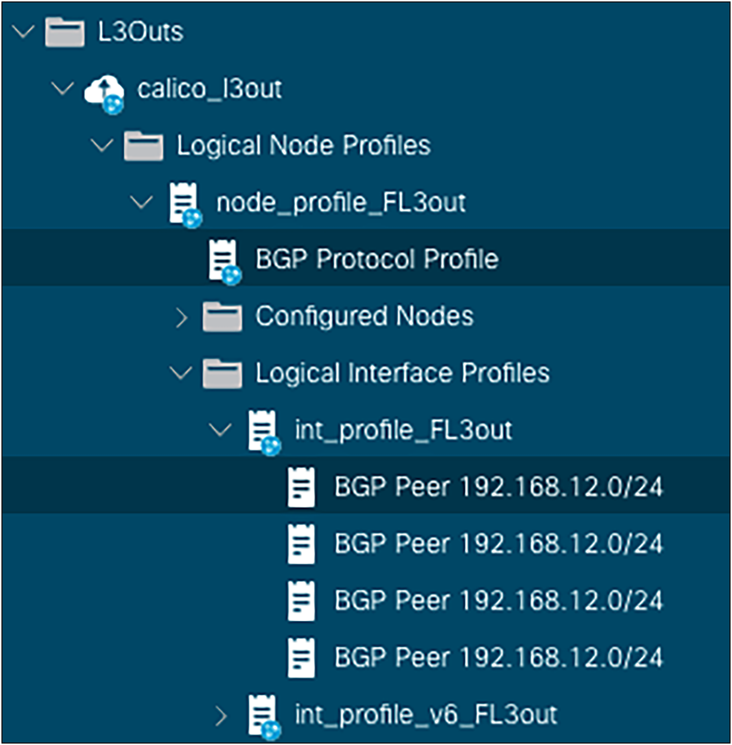
BGP Neighbors Configuration
Each neighbor’s state can be also verified as shown in the following figure:
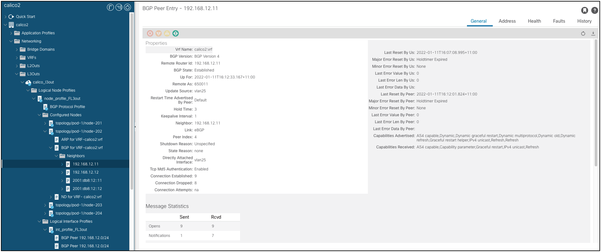
BGP Neighbor State
Finally, the routes learned from the K8s nodes are rendered at the L3Out VRF level, as shown in the figure below:
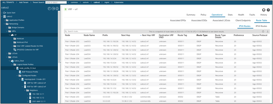
VRF Routing Table
In order to apply micro segmentation based on specific pod endpoints or services exposed by the K8s cluster, it is possible to create other external EPGs and match the specific workload intended for micro segmentation. Contracts including service graphs and PBR are supported for this use case. A typical use case would be to redirect traffic for specific critical services to a firewall that would log and perform network traffic analysis.
Tested Kubernetes distributions
Theoretically, any K8s distribution can support this architecture as long as the CNI plugin support peering through BGP.
At the time of writing, the following combinations have been tested:
● Upstream Kubernetes
◦ Calico
◦ Cilium
◦ Kube-router
● OpenShift 4.x
◦ Calico
● Tanzu
◦ Calico
By combining Cisco ACI and Calico, customers can design Kubernetes clusters that can deliver both high performance (no overlays overhead) as well as providing exceptional resilience while keeping the design simple to manage and troubleshoot.
| Version |
Date |
Change |
| 1.0 |
July 10, 2019 |
Initial Release |
| 2.0 |
January 14, 2022 |
Floating SVI |
| 2.1 |
December 16, 2022 |
Kube-Router Support |
| 2.2 |
July 26, 2023 |
Cilium Support, Tested Kubernetes Distros |
In case of IP exhaustion, a node can potentially borrow IPs from a different node pod subnet. In that case, a host route will be advertised from the node for the borrowed IP.
More details on the Calico IPAM can be found here: https://www.projectcalico.org/calico-ipam-explained-and-enhanced
[7] This is the default behavior. Additional /26 subnets will be allocated to nodes automatically if they exhaust their existing /26 allocations. In addition, the node may advertise /32 pod specific routes if it is hosting a pod that falls outside of its /26 subnets. Refer to https://www.projectcalico.org/calico-ipam-explained-and-enhanced for more details on Calico IPAM configuration and controlling IP allocation for specific pods, namespaces, or nodes.