Cisco ACI Multi-Site/Multi-Pod and F5 BIG-IP Design Guide
Available Languages
Bias-Free Language
The documentation set for this product strives to use bias-free language. For the purposes of this documentation set, bias-free is defined as language that does not imply discrimination based on age, disability, gender, racial identity, ethnic identity, sexual orientation, socioeconomic status, and intersectionality. Exceptions may be present in the documentation due to language that is hardcoded in the user interfaces of the product software, language used based on RFP documentation, or language that is used by a referenced third-party product. Learn more about how Cisco is using Inclusive Language.
This document describes design considerations in Cisco® Application Centric Infrastructure (Cisco ACI®) Multi-Site and Multi-Pod environments with F5 BIG-IP, specifically with F5 BIG-IP DNS and LTM modules. The following use cases are covered in this document:
● North-south and east-west load-balancing service insertion design
● Independent clustered load-balancing service nodes in each data center
● Layer 3 BIG-IP LTM design
● BIG-IP DNS design
This document assumes that the reader has a basic knowledge of Cisco ACI technologies and F5 BIG-IP technologies, especially Cisco ACI Multi-Pod, Multi-Site, F5 BIG-IP Local Traffic Manager (LTM), and BIG-IP Domain Name System (DNS). To learn the basics of these functionalities, refer the following documents:
● F5 BIG-IP LTM design in Cisco ACI: Cisco ACI and F5 BIG-IP Design Guide White Paper
● Cisco ACI Multi-Pod: Cisco ACI Multi-Pod White paper
● Cisco ACI Multi-Site: Cisco ACI Multi-Site Architecture White Paper
● Cisco ACI L4-L7 Service integration: Cisco ACI PBR Service Graph Design White paper
● F5 BIG-IP DNS concept: F5 BIG-IP DNS Concepts
For more information, see the Cisco ACI white papers available at Cisco.com: https://www.cisco.com/c/en/us/solutions/data-center-virtualization/application-centric-infrastructure/white-paper-listing.html.
As of Cisco Application Policy Infrastructure Controller (APIC) Release 6.0(2), the recommended design options for integrating BIG-IP load balancer services in Cisco ACI Multi-Site and Multi-Pod architectures are the following:
BIG-IP LTM design recommendation:
● Cisco ACI Multi-Pod: One active/standby load-balancer pair stretched across pods or an active/standby load-balancer pair in each pod (Figure 1)
● Cisco ACI Multi-Site: Independent load balancers in each site (Figure 2)
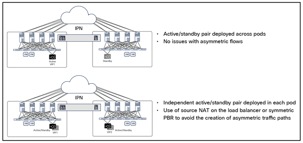
Recommended load balancer deployment options with Cisco ACI Multi-Pod
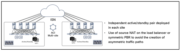
Recommended Load Balancer deployment options with Cisco ACI Multi-Site
It’s recommended to enable the following features on each BIG-IP LTM pair:
● HA groups or Fail-Safe for failover management
● MAC Masquerade
Please refer to the HA design considerations section in this document for more information on BIG-IP LTM High Availability design options and considerations.
F5 BIG-IP DNS (GSLB) design recommendation:
● Standalone F5 BIG-IP DNS with only DNS module deployed on an individual BIG-IP
● Multiple standalone F5 BIG-IP DNSs across data centers in the same DNS synchronization group to avoid a single point of failure at all times, which minimizes the risk of a complete DNS outage
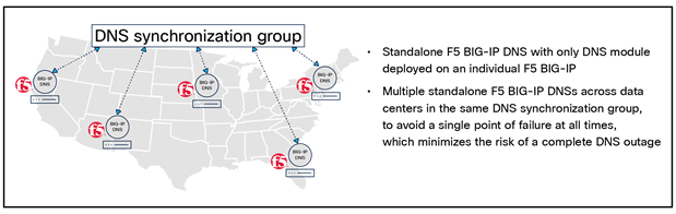
Recommended F5 BIG-IP DNS GSLB deployment option
Please refer F5 BIG-IP DNS design considerations section in this document for more information on BIG-IP DNS GSLB design considerations.
F5 BIG-IP is a family of products covering both software and hardware designed around application availability, access control, and security solutions. BIG-IP can mean a single software module in BIG-IP's software family, or it can mean a hardware chassis located in the data center.
BIG-IP hardware offers several types of purpose-built custom solutions. There are two primary variations of BIG-IP hardware:
● Single chassis design: F5 BIG-IP iSeries and F5 rSeries
● Modular chassis design: F5 VIPRION and F5 VELOS
The rSeries is the new generation of single chassis design while VELOS is the new generation of modular chassis designs. For more information on rSeries please refer to: F5 rSeries Appliance. For more information on VELOS please refer to: F5 VELOS Hardware Chassis and Blades.
F5 BIG-IP software products are licensed modules that can run on F5 BIG-IP hardware or can run in virtualized environments. Virtualized systems provided F5 BIG-IP software functionality where hardware implementations are unavailable, including public clouds and various managed infrastructures where rack space is a critical commodity.
There are several software modules offered by F5 BIG-IP. This document focuses on the design and deployment considerations with F5 BIG-IP LTM and DNS.
● F5 BIG-IP LTM is central to F5's full traffic proxy functionality. It provides a platform for creating virtual servers, performance, service, protocol, authentication, and security profiles to define and shape application traffic. BIG-IP LTM is used as a foundation for enhanced services in most other BIG-IP software modules.
● F5 BIG-IP DNS, formerly Global Traffic Manager (GTM), provides similar security and load-balancing features that LTM offers but at a global or multi-site scale. It offers services to distribute and secure DNS traffic advertising application namespaces.
All variations of F5 BIG-IP hardware and software work with Cisco ACI. If a BIG-IP virtual edition (F5 BIG-IP VE) is used, a VMM domain integration such as VMware VMM domain and Microsoft SCVMM domain can be used in Cisco ACI.
F5 BIG-IP DNS is a system that monitors the availability and performance of global resources and uses that information to manage network traffic patterns. BIG-IP DNS uses load balancing algorithms, topology-based routing, and iRules to control and distribute traffic according to specific policies.
F5 BIG-IP DNS terminology
The following are definitions of F5 BIG-IP terminology commonly seen on BIG-IP DNS and used in this document:
● Listeners: a listener is a specialized virtual server that passively checks for DNS packets on port 53 on the IP address you assigned to the listener.
● Virtual server: (VIPs): a virtual server is a traffic management object that is represented by a virtual IP address (VIP) and a service that listens for client requests.
● Pool members: a pool member defined in F5 BIG-IP DNS is a virtual server (VIP).
● Pools: a BIG-IP DNS pool contains one or more virtual servers (VIPs).
● Servers: a server defined in BIG-IP DNS is either a F5 BIG-IP LTM or a non-F5 system that is responsible for virtual server services (VIPs).
● Wide IPs: a wide IP maps a Fully Qualified Domain Name (FQDN) to one or more pools of virtual servers (VIPs) that host the content of the domain.
● Data centers: a BIG-IP DNS data center is a specific geographic location where a group of virtual servers (VIPs) reside. The data center configuration will allow F5 BIG-IP DNS to understand the location of the virtual services (VIPs) for global server load balancing.
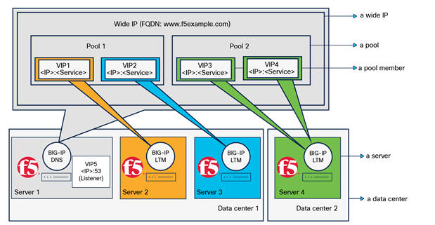
F5 BIG-IP DNS terminology
F5 BIG-IP DNS provides tiered global server load balancing (GSLB) that intelligently distributes traffic among a group of servers located in different geographical locations regardless of whether they are virtual or physical servers or in private or public clouds.
F5 BIG-IP DNS has two stages for GSLB:
1. Wide IP level load balancing: F5 BIG-IP DNS first selects the best available pool for the requested wide IP (FQDN).
2. Pool level load balancing: after the best available pool is selected for the requested wide IP (FQDN), BIG-IP DNS selects the best available virtual server (VIP) in the selected pool using the three tiers of load balancing.
◦ Preferred load-balancing method: this is the first pool-level load-balancing method to select a VIP.
◦ Alternate load-balancing method: if the Preferred load-balancing method fails to select a VIP, the selected Alternate load-balancing method is used.
◦ Fallback load-balancing method: if the Alternate load-balancing method also fails to select a VIP, the Fallback load-balancing method is used. Note that the availability status of VIPs is ignored at the selected Fallback load-balancing method to ensure that BIG-IP DNS can return a VIP to the DNS request.
◦ If all of the configured load-balancing methods fail to select a valid VIP, F5 BIG-IP DNS uses the local BIND (Berkeley Internet Name Domain) to resolve the DNS request.
To select the best available resources (a pool for wide IP-level load balancing and a VIP for pool-level load balancing), F5 BIG-IP DNS supports static and dynamic load-balancing methods:
● When a static load-balancing method is used, F5 BIG-IP DNS selects a resource based on a predefined pattern; for example, proximity-based topology location and weighted round robin.
● When a dynamic load-balancing method is used, F5 BIG-IP DNS selects a resource based on dynamically collected performance metrics such as CPU processing time, number of BIG-IP LTM connections, packet rate, etc.
Note that only the static load-balancing method can be used for wide IP level load balancing whereas three-tiered pool-level load balancing can use either a static or a dynamic load-balancing method at each tier. To explore all available F5 BIG-IP DNS GSLB static and dynamic load-balancing methods, please refer to:
F5 BIG-IP DNS documentation that explains Global Server Load Balancing.
The figure below illustrates an example of BIG-IP DNS GSLB behavior.
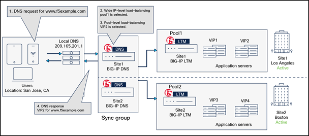
F5 BIG-IP DNS GSLB behavior overview
1. DNS request for www.f5example.com.
A user in San Jose, California, sends a DNS request (FQDN: www.f5example.com to the local DNS (209.165.201.1) that sends a DNS request to the BIG-IP DNS in site1 (Los Angeles). Note that BIG-IP DNS in site1 and site2 are in the same sync group, which means they act as a single logical unit. The DNS request could be forwarded to either one of the DNSs depending on the local DNS’s decision, and the DNS response will have the same result.
2. Wide IP level load balancing: BIG-IP DNS selects pool1 in site1 (Los Angeles).
F5 BIG-IP DNS receives the DNS request and tries to identify the best available pool for the requested wide IP (FQDN: www.f5example.com) based on the configured static load-balancing method. The figure below shows a wide IP-level load-balancing configuration example using a static load-balancing method called “Topology,” which resolves the DNS request for the requested wide IP based on the physical proximity to the client who sends the DNS request. When "Topology" is used, a load-balancing decision is based on the defined “Topology Records." Each "Topology Record" has the following elements:
◦ LDNS (local DNS) request source statement: this defines the origin of the DNS request.
◦ Destination statement: this defines the resource to which F5 BIG-IP DNS will direct the DNS request. Please note that the resource can only be a pool for wide IP-level load balancing, while for pool-level load-balancing, the resource can be a data center, an IP subnet, etc.
◦ Operator: this can be "is" or "is not," and is used in the LDNS request source statement and destination statement.
◦ Weight (or score): BIG-IP DNS assigns the configured weight (or score) to the destination resource (a pool for wide IP-level load balancing or a VIP for pool-level load balancing) that matches the Topology Record.
For more information on "Topology Record," please refer to: Overview of BIG-IP DNS Topology Records.
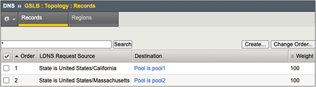
Example of a wide IP-level load-balancing configuration: static load-balancing method “Topology”
In this example, two “Topology Records” are defined. F5 BIG-IP DNS iterates through the list of all Topology Records in the order shown and assigns a weight (or score) to each pool based on the matching Topology Records. Pool1 matches the first "Topology Record" in the list because the DNS request originates from an LDNS located in San Jose in the state of California in the United States. Thus, F5 BIG-IP DNS assigns a weight of 100 to pool1. The weight for pool2 is 0 because there is no matching Topology Record (the DNS request does NOT originate from a LDNS located in the state of Massachusetts in the United States). Since pool1 has the highest weight (or score), pool1 is selected for wide IP-level load balancing.
"Topology" is a static load-balancing method that can be used for pool-level load balancing too.
3. Three-tiered pool-level load balancing: BIG-IP DNS selects VIP2 address.
After the best available pool is selected for the requested wide IP (FQDN), BIG-IP DNS selects the best available virtual server (VIP) within the selected pool based on the three tiers of the pool-level load-balancing method. The figure below shows a configuration example.
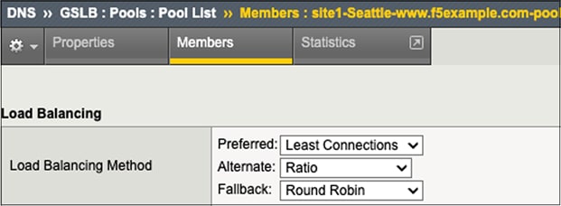
Example of a pool-level load-balancing configuration
In this example, “Least Connections” is used for the Preferred load-balancing method. As a result, VIP2, which is owned by the BIG-IP LTM at site1, is selected in this example because it currently hosts the fewest (“least”) connections among all VIPs in pool1. “Least connections” is one of the dynamic load-balancing methods available in Preferred load-balancing methods at pool-level load balancing, which selects the best available VIP that hosts the fewest connections at the time the request is received.
4. DNS response (www.f5example.com is resolved with VIP2.)
Cisco ACI Multi-Site and Multi-Pod with F5 BIG-IP DNS and LTM
Cisco ACI Multi-Site/Multi-Pod solution interconnects multiple Cisco ACI fabrics that can be geographically dispersed. In combining F5 BIG-IP DNS and LTM solutions, we can improve application performance and provide application resiliency and robustness across data centers. The figure below shows an example of a sunny day scenario where application services are delivered efficiently to the users based on their geographical locations to enhance user application experience.
Application delivery in a sunny day scenario
In case of unexpected events, such as a data center goes down due to power outage caused by a storm, or the data center becomes unreachable due to a network outage, the F5 BIG-IP LTM and DNS solutions can continue application delivery by redirecting the application requests to the next available virtual servers (VIPs) in a different data center so that the application can continue to be available (Figure 9). Although the topology example uses Cisco ACI Multi-Site, the same concept is applicable to Cisco ACI Multi-Pod as well.
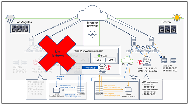
Application delivery in a rainy day scenario
As explained in the F5 BIG-IP DNS section of this document, F5 BIG-IP DNS provides tiered GSLB capability to resolve a DNS request for a Fully Qualified Domain Name (FQDN) and to return an IP address of a virtual server (VIP) that can reside across data centers. Traffic sourced from the clients goes through the F5 BIG-IP LTM that owns the selected VIP and then will go to an associated real server that is in the same data center or a different data center. A real server is a physical or virtual server that hosts an application.
The key network design considerations to use F5 BIG-IP DNS and BIG-IP LTM are the following:
● Communication between BIG-IP DNS and LTM through iQuery: this is important to establish communication between BIG-IP DNS and LTM so that they can exchange information, which allows BIG-IP DNS to select the best available BIG-IP LTM VIP across data centers for a DNS request from a client. Based on the information from BIG-IP LTM in each data center, BIG-IP DNS can direct traffic away from a data center that, for example, experienced an outage or is performing poorly. A BIG-IP system communicates to another BIG-IP system using iQuery, which is an F5 proprietary protocol running on port 4353. Thus, TCP port 4353 must be opened on the BIG-IP DNS and BIG-IP LTM, and it must also be allowed in the network between the BIG-IP DNSs and BIG-IP LTMs. All iQuery communications are encrypted through SSL. TCP port 22 also needs to be opened because secure shell (SSH) protocol is used for iQuery SSL certificates exchange between BIG-IP LTM and DNS so that they are authorized to communicate with each other.
● Application traffic through BIG-IP LTM: F5 BIG-IP LTM is a stateful device; we need to ensure both directions of traffic go through the same BIG-IP LTM (except for Direct Server Return (DSR), which does not have such a requirement); otherwise, the traffic will be dropped. Source Network Address Translation (SNAT) and ACI Policy-Based Redirect (PBR) are options that we can use to fulfill such requirements as steering return traffic sourced from the real server and destined to the client through the same BIG-IP LTM.
Here are some questions that can help in better understanding the requirements and derive a possible design satisfying them:
● How do we handle return traffic from the real server to the client? Is BIG-IP LTM using SNAT or Cisco ACI fabric using PBR to steer return traffic to the same BIG-IP LTM?
● Are the VIP and its real servers deployed in the same data center or distributed across data centers?
● Is there a requirement to configure the BIG-IP LTM interfaces (self IP) in different data centers in the same bridge domain or different bridge domains?
● Is the VIP in the same subnet as the BIG-IP LTM interface (self IP) or outside of the subnet?
● What High Availability (HA) option is used for BIG-IP LTM: an independent active/standby HA pair or active/active HA pair in each data center? Or an active/standby HA pair or active/active HA pair stretched across data centers?
● How does the traffic flow between BIG-IP DNS and LTM for information exchange? Is there a firewall in the path between them?
● Where should we deploy BIG-IP DNS to optimize the latency in DNS responses?
● How can we avoid a complete BIG-IP DNS outage? By using multiple standalone BIG-IP DNSs across data centers in different regions? By using high availability BIG-IP DNS pairs? Or by creating a BIG-IP DNS synchronization group for BIG-IP DNSs?
The following subsections in this section will explain the following design considerations:
● F5 BIG-IP DNS design considerations
● F5 BIG-IP LTM design considerations
F5 BIG-IP DNS design considerations
This subsection explains F5 BIG-IP DNS design considerations: BIG-IP DNS deployment locations and DNS high availability.
To optimize the latency in DNS responses, the location of BIG-IP DNS deployment is very important. While it is common to deploy BIG-IP DNSs in data centers that are larger in size, we should also consider the type of services provided as well as service volumes. For example, if large data centers are in close proximity, whereas many services are accessed globally, it may be better for BIG-IP DNSs to be spread out geographically to multiple regions instead of being located in a single region, to provide lower latency for DNS responses across the globe.
We should always be prepared to avoid the risk of a complete DNS outage whether it is caused by expected events (such as maintenance or upgrade tasks) or unexpected events (such as a power outage). It is recommended to deploy those systems in such a way not to expose any single point of failure even when one of the systems has failed. For example, a minimum of three single standalone BIG-IP DNSs in the same DNS synchronization group is better than just two single standalone BIG-IP DNSs, so that a single point of failure can be avoided when one of the BIG-IP DNSs has failed, whether unexpectedly or expectedly. A standalone BIG-IP DNS is an individual BIG-IP with only a DNS module deployed, and it can be single or in an HA pair. A BIG-IP DNS synchronization group (sync group) is a collection of BIG-IP DNSs that have synchronized configuration settings and metrics information.
When BIG-IP DNSs are in the same synchronization group, they work together to monitor the availability and performance of global resources (such as data centers, VIPs, etc.) and use that information to manage network traffic patterns. The figure below illustrates an example of BIG-IP DNS deployment for global application services. In this example, there are four colored regions: blue, yellow, red, and grey. In each region, there are BIG-IP LTM systems deployed in data centers and a standalone BIG-IP DNS deployed in one of the data centers. For example, the blue region has a BIG-IP DNS deployed in DC1, which communicates to the BIG-IP LTM deployed in the blue data centers, through iQuery, only in its own blue-colored region. The same goes for the other colored regions: yellow, red, and purple. The wide IP for www.f5example.com is configured only on the blue region's BIG-IP DNS in DC1, which has two pools of virtual servers (VIPs) hosted on the BIG-IP LTMs in the blue data centers.
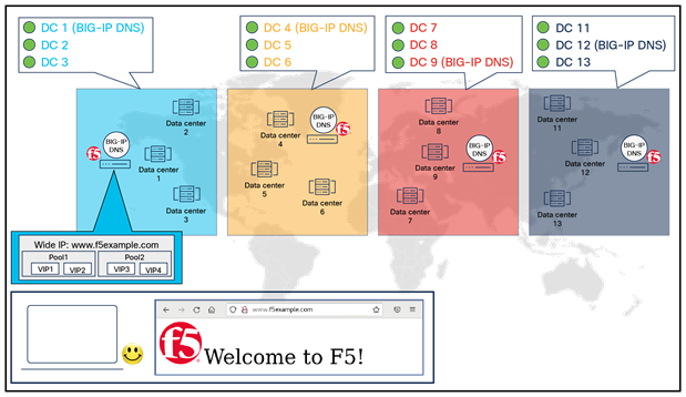
Example of a BIG-IP DNS deployment for global application services without DNS synchronization
In this example, DNS synchronization is not enabled, and if the BIG-IP DNS in DC1 has failed, or if DC1 goes down, DNS requests for www.f5example.com will be impacted as illustrated in the figure below because BIG-IP DNS in DC1 is the only BIG-IP DNS configured for wide IP www.f5example.com and communicates with BIG-IP LTMs in the blue data centers.
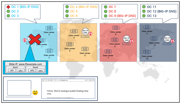
Example of a BIG-IP DNS deployment for global application services without DNS synchronization (failure scenario)
The figure below shows the same example, but with DNS synchronization enabled, and with all the BIG-IP DNS systems that are part of the same synchronization group. When the BIG-IP DNS are in the same synchronization group, they share and synchronize configuration settings and metrics information as if they worked as a single entity. As a result, the wide IP www.f5example.com configuration is now synchronized among all BIG-IP DNS systems that are part of the same synchronization group.
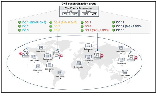
Example of a BIG-IP DNS deployment for global application services with DNS synchronization
If the blue BIG-IP DNS in DC1 fails or DC1 goes down due to an unexpected event, the DNS request for www.f5example.com will not be impacted because the rest of the BIG-IP DNS in the same synchronization group (yellow BIG-IP DNS in DC4, red BIG-IP DNS in DC9, and grey BIG-IP DNS in DC12) can continue to direct the traffic accordingly, as illustrated in the figure below. As you can easily understand from this example, the use of DNS synchronization is strongly recommended in BIG-IP DNS deployments.
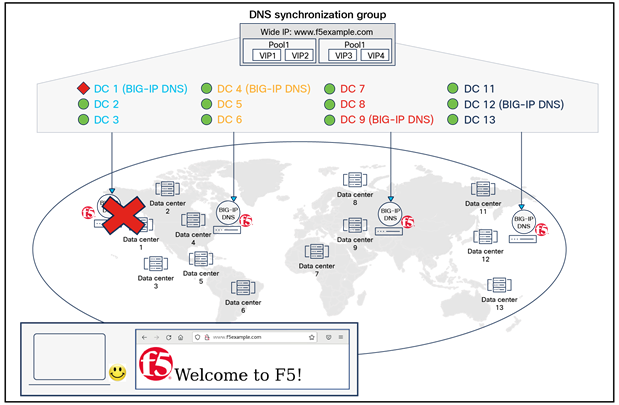
Example of a BIG-IP DNS deployment for global application services with DNS synchronization (failure scenario)
Along with GSLB, here are some of the services offered by F5 BIG-IP DNS:
● DNS Express: an engine that provides the ability for the BIG-IP system to act as a high-speed, authoritative DNS server
● Domain Name System Security Extensions (DNSSEC): an industry-standard protocol that functions as an extension to the Domain Name System (DNS) protocol. BIG-IP DNS uses DNSSEC to guarantee the authenticity of DNS responses, including zone transfers, and to return denial of existence responses, thus protecting your network against DNS protocol and DNS server attacks.
● DNS Caching: this allows BIG-IP to respond quickly to repeated DNS queries, which enhances DNS performance significant ways.
● DNS64: this handles IPv6-only client connection requests to IPv4-only servers on the network by returning an AAAA record response to the client.
For more information on all available services on F5 BIG-IP DNS, please refer https://www.f5.com/pdf/products/big-ip-dns-datasheet.pdf.
From the device configuration management perspective, F5 BIG-IQ Centralized Management is a tool that can manage multiple BIG-IP systems and all of their services from one centralized location. Instead of individual logins to each BIG-IP DNS and BIG-IP LTM, BIG-IQ Centralized Management can be used to manage them from a single pane of glass through a user-friendly GUI, or simply through APIs. BIG-IQ Centralized Management will be a good option to unify the management of all BIG-IP systems deployed in the data centers. It can manage licensing and can collect analytics from BIG-IP systems as well. For more information on BIG-IQ, please refer to F5 BIG-IQ Centralized Management.
F5 BIG-IP LTM design considerations
Overview
Traffic symmetricity is important for multilocation data centers along with stateful devices. Since BIG-IP LTM is a stateful device, a critical requirement to integrate BIG-IP LTM into Cisco ACI Multi-Site or Multi-Pod is to ensure that both directions of traffic flow are steered through the same BIG-IP LTM in the same data center. Otherwise, the connection will be dropped due to lack of state on the BIG-IP LTM (one exception is Direct Server Return (DSR), which does not have this requirement and is not covered in this document).
Cisco has the following recommendations and white papers for stateful service device design in Cisco ACI Multi-Pod and Multi-Site:
● Cisco ACI Multi-Pod: Cisco ACI Multi-Pod and Service Node Integration White Paper
● Cisco ACI Multi-Site: Cisco ACI Multi-Site and Service Node Integration White Paper
Besides traffic symmetricity, Cisco ACI and F5 BIG-IP Design Guide White Paper discusses various F5 BIG-IP LTM design considerations that are also important and applicable when integrating BIG-IP LTM into ACI Multi-Site or Multi-Pod.
As the forwarding design considerations are already covered in the existing white papers, this subsection focuses on BIG-IP LTM High Availability (HA) design options and considerations.
This section covers the following BIG-IP LTM HA design considerations:
● HA modes
● Failover types
● Managing failover
● MAC Masquerade
HA modes
You can set up one of the two HA modes with a pair of BIG-IP LTMs:
● Active/standby mode (recommended): only one of the BIG-IP LTM is active at any given time. The BIG-IP LTM that is in an active state is the only system that is actively processing traffic while the other BIG-IP LTM remains in a standby state and is ready to take over if failover occurs.
● Active/active mode: both BIG-IP LTM are active and they both process traffic for different VIPs simultaneously. If one of the BIG-IP LTMs becomes unavailable for any reason, the other BIG-IP LTM automatically begins processing traffic for the unavailable peer while continuing to process the VIP traffic for its own.
There is only one active BIG-IP LTM processing a particular VIP’s traffic at any given time in either of the BIG-IP LTM HA modes. Unlike deploying an independent HA pair (active/active or active/standby) in each data center in Cisco ACI Multi-Site or Multi-Pod (which we will discuss in coming sections), when a BIG-IP LTM HA pair is stretched across data centers in Cisco ACI Multi-Pod, there is always traffic symmetricity no matter which HA mode is deployed.
The figure below illustrates an example using active/standby mode HA pair deployed across data centers in Cisco ACI Multi-Pod. In this example, all VIP traffic is processed by the active BIG-IP LTM in data center 1.
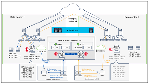
Example of a BIG-IP LTM deployment: HA pair across pods (active/standby mode)
The figure below shows an example using an active/active HA pair deployed across data centers in Cisco ACI Multi-Pod, where the active BIG-IP LTM in data center 1 processes traffic for VIP1 while the active BIG-IP LTM in data center 2 processes traffic for VIP2.
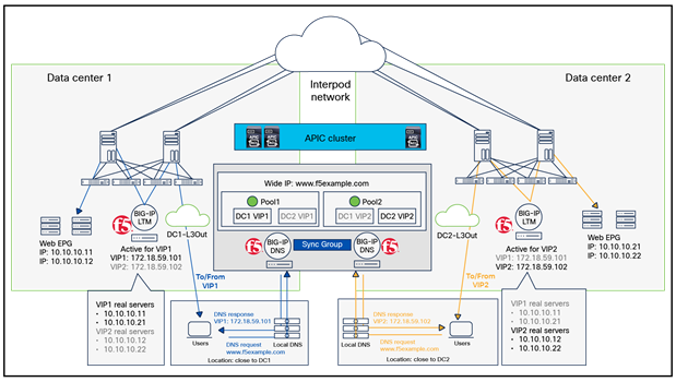
Example of a BIG-IP LTM deployment: HA pair across pods (active/active mode)
Failover types
To enable a device to failover to its peer device, there are two failover types available for BIG-IP LTM HA:
● Hard-wired failover: this is based on a simple mechanism where the active system asserts (or de-asserts) a voltage (CTS/RTS) signal to indicate active status.
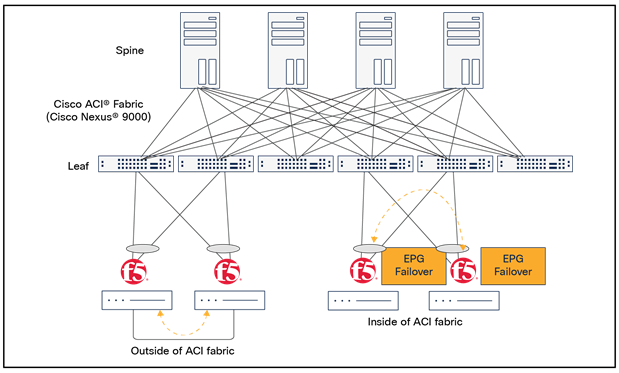
● Network failover: this is based on heartbeat detection where the system sends heartbeat packets over the internal IP network, and there are two options to implement network failover, as shown in the figure below:
◦ Outside the ACI fabric – Network failover traffic (the heartbeats) is carried outside the ACI fabric and does not require EPG configuration. The two BIG-IP LTMs are connected through a direct connection or another network device for the exchange of heartbeat messages.
◦ Inside the ACI fabric – Network failover traffic (the heartbeats) is carried within the ACI fabric; this requires EPG configuration.
Please note that if both failover types are used (network failover is configured while a hard-wired failover cable also connects the two BIG-IP LTMs), hard-wired failover will always take precedence. In other words, if network failover traffic is compromised, failover will not happen because the hard-wired failover cable still connects the two BIG-IP LTMs.
Network failover design options
Network failover may be more desirable than hard-wired failover, especially when a BIG-IP LTM HA pair is stretched across data centers, because network failover does not have a distance limitation between the two BIG-IP LTMs, whereas hard-wired failover has a maximum distance limit of 50 feet between them; also, network failover supports both HA modes, whereas hard-wired failover supports only active/active, etc. For more information on comparisons between hard-wired failover and network failover, please refer to: https://my.f5.com/manage/s/article/K2397.
Note: Network failover is based on heartbeat detection where heartbeat packets are sent over the internal network. The BIG-IP LTM in standby state considers the peer down after a Failover.NetTimeoutSec timeout value is exceeded, and it will attempt to switch to the active state. The default Failover.NetTimeoutSec is three seconds; we recommend caution when changing this value. This is because, while you can increase the Failover.NetTimeoutSec to accommodate the latency of the network failover traffic between the two BIG-IP LTMs, whether they are in the same data center or in different data centers, the failover can be delayed if, or when, a failure occurs.
Managing failover
You can configure HA groups or a Fail-Safe to initiate failover according to defined events. The use of either one of these is highly recommended, especially if the network failover traffic is carried outside the ACI fabric. In this document, an HA group is used to explain how to avoid traffic loss.
The figure below illustrates an example where an active/standby BIG-IP LTM HA pair is stretched across data centers in ACI Multi-Pod, and the two BIG-IP LTMs exchange heartbeats outside the ACI fabric through a direct connection between them. In this example, the failover does not happen when the active BIG-IP LTM in data center 1 loses its uplinks to the ACI fabric because the heartbeats are exchanged through the direct connection between the two BIG-IP LTMs, and the heartbeats’ exchange is not interrupted by an uplink failure. As a result, traffic destined to the VIP is impacted in this example, Return to DNS is configured as the Fallback load-balancing method at the pool-level load balancing on the BIG-IP DNS. Thus, BIG-IP responds with all VIPs (both VIP1 and VIP2, as shown in the figure below) to the DNS request from the local DNS without referring to the other load-balancing methods because all of the DNS pool members are down. To change the BIG-IP DNS behavior on how it resolves a DNS request when all of the pool members are down or disabled, please refer to this article for more information: https://my.f5.com/manage/s/article/K39000314).
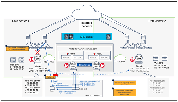
Example of network failover outside ACI fabrics without an HA group (A BIG-IP LTM HA pair is stretched across data centers in Cisco ACI Multi-Pod.)
The traffic-loss problem explained in the figure above can be avoided by configuring an HA group. The figure below illustrates the same example with an HA group configured to monitor the uplinks to the ACI fabric as well as the reachability to its gateway. When the uplinks go down, a failover to its peer with the best HA score was initiated (the BIG-IP LTM in data center 2 in this example) while the heartbeats continue to exchange outside the ACI fabric.
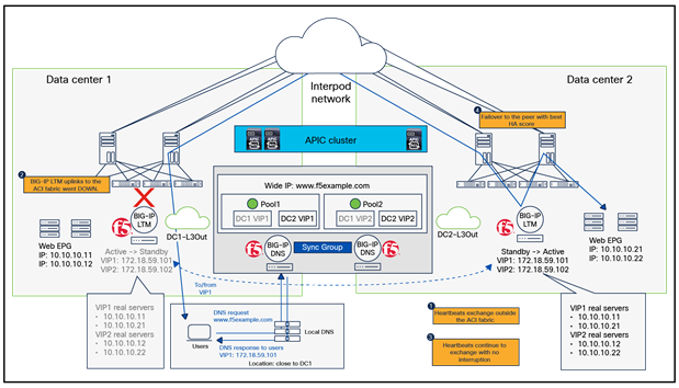
Example of network failover outside ACI fabrics with an HA group (A BIG-IP LTM HA pair is stretched across data centers in Cisco ACI Multi-Pod).
For more information on managing failover, please go to https://techdocs.f5.com/en-us/bigip-14-1-0/big-ip-device-service-clustering-administration-14-1-0/managing-failover.html.
MAC Masquerade
MAC masquerading is a feature that allows you to manually allocate a MAC address to a traffic group across a BIG-IP LTM pair configured for high availability. More specifically, this MAC address floats between the devices in an HA pair, along with the floating self IPs and virtual addresses within the same traffic group. MAC Masquerade is highly recommended under the following conditions:
● To improve reliability and failover speed in lossy networks by minimizing Address Resolution Protocol (ARP) table updates on servers and network devices that are in the same broadcast domain with BIG-IP LTM during traffic group failover
● When using Policy-Based Redirect (PBR) in Cisco ACI, unless dynamic MAC detection with IP-SLA tracking is enabled
Design options for north-south/east-west traffic flows
The figure below illustrates the common BIG-IP design options for north-south traffic flows (traffic flows between servers in the data center and clients in the external network):
● ACI fabric as the default gateway for the real servers in the data center and use of either SNAT on the BIG-IP LTM or ACI PBR to steer to BIG-IP LTM the return traffic flows between real servers and external clients
● BIG-IP LTM as the default gateway for the real servers, without the use of SNAT or PBR
● ACI fabric as the default gateway for the real servers and deployment of a “VRF sandwich” configuration to deploy the BIG IP LTM in line with the traffic flows (there is no need for either SNAT or PBR)
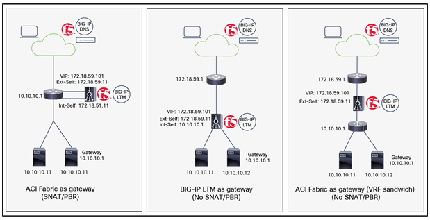
Common BIG-IP design options
This section explains the traffic flows and deployment considerations for the use cases above in Cisco ACI Multi-Site, which are applicable to Cisco ACI Multi-Pod deployments as well, with the assumptions listed below that represent common BIG-IP DNS and LTM deployment best practices:
● Independent active/standby HA pair of BIG-IP LTMs is deployed in routed mode (L3) in each data center.
● Standalone BIG-IP DNS is deployed, which means the DNS module and LTM module are deployed separately on individual BIG-IP devices.
● A BIG-IP DNS is deployed in major regional data centers, all of which are part of the same DNS synchronization group.
A BIG-IP DNS is typically deployed as a shared resource among multiple tenants whereas an HA pair of BIG-IP LTMs is deployed for each tenant or is used as a shared resource among multiple tenants. For BIG-IP LTM multitenant design, please see Cisco ACI and F5 BIG-IP Design Guide White Paper.
Though this document focuses on north-south traffic flows, the same design considerations are also applicable to east-west traffic flows that are traffic flows between real servers through load balancers within and across data centers.
The first design option is “ACI fabric as default gateway with SNAT.” This design option is used as an example to highlight the differences between a design with a service graph and one without a service graph.
ACI fabric as default gateway with SNAT
Figures 20 and 21 illustrate a Cisco ACI network design example for north-south traffic with routed BIG-IP LTM using SNAT and ACI fabric as the default gateway for the real servers.
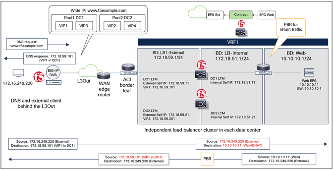
Figure 20 illustrates a design leveraging a service graph (without PBR) for BIG-IP LTM insertion. Because a service graph is used, the service Bridge Domains (BDs) must be stretched across sites, which means the BIG-IP LTM interfaces (or self IPs) in different data centers must be part of the same service BD. A contract associated with a BIG-IP LTM service graph is required between the L3Out EPG (connecting to the external clients) and the Web EPG. There is no need to create EPGs for the BIG-IP LTM external and internal interfaces by users because the EPGs for the service device and required security rules (which are called zoning-rules in Cisco ACI) are created automatically as part of service graph deployment. The endpoints in the Web EPG are real servers associated to the VIP defined on the BIG-IP LTM device, and the assumption here is that each BIG-IP LTM HA pair in each data center offers a unique VIP address that is part of the same stretched service BD. In this example, the service BD, the Web BD, and the L3Out are defined in the same VRF.
Example of a north-south BIG-IP LTM with SNAT design (with a service graph)
Figure 21 shows the same design example without a service graph. Because a service graph is not used, a stretched service BD across data centers is not mandatory, which means the BIG-IP interfaces (or self IPs) in different data centers can be part of the same service BD or different service BDs. As shown in Figure 21, the service BDs are not stretched in this example. Since a service graph is not used, two different contacts are required: one contract is established between the L3Out EPG (connecting to the external clients) and the BIG-IP LTM EPG for its external interface; and the other contract is between the other BIG-IP LTM EPG for its internal interface and the Web EPG. The endpoints in the Web EPG are real servers associated to the VIP of the BIG-IP LTM, and the assumption here is that each BIG-IP LTM HA pair in each data center has assigned a unique VIP address that is part of different service BDs. In this example, the service BDs, the Web BD, and the L3Out are defined in the same VRF.
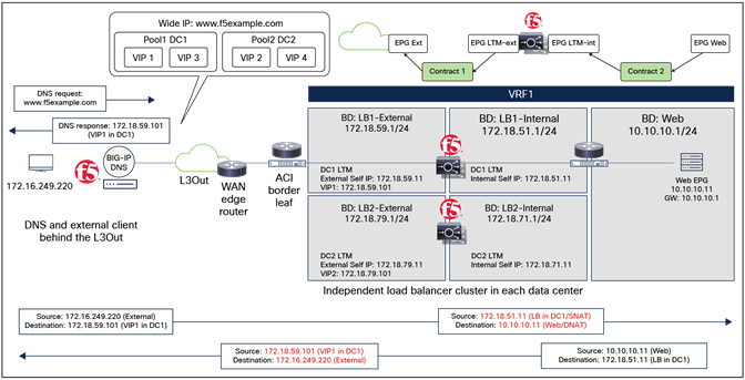
Example of a north-south BIG-IP LTM with SNAT design (with no service graph)
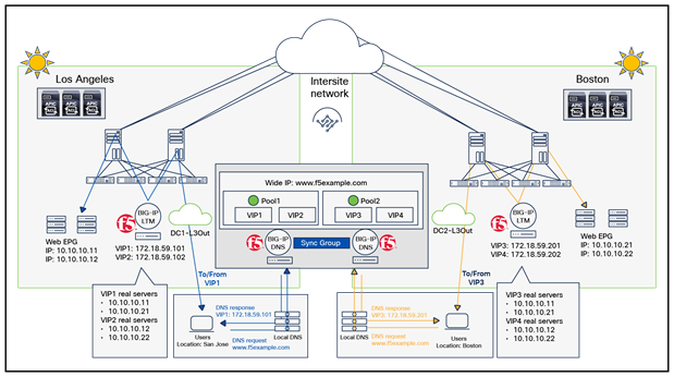
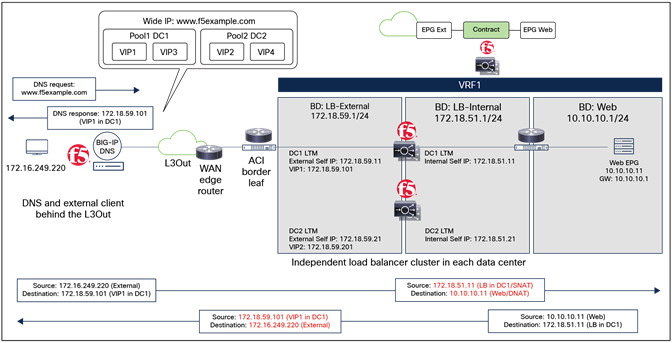
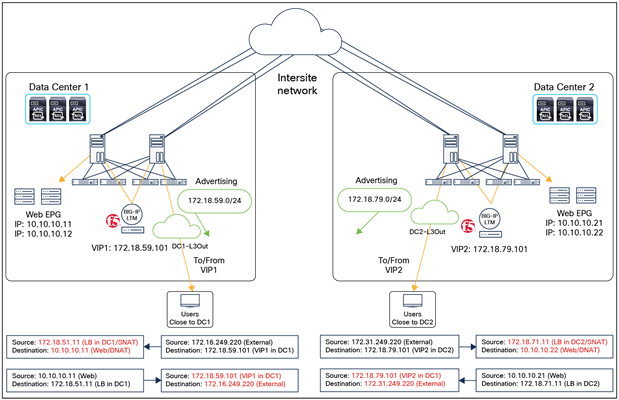
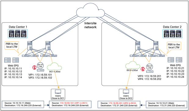
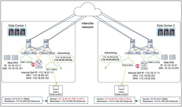
Figures 22, 23, and 24 show an example of a traffic flow including a DNS request and response using BIG-IP DNS. In this example, DC1 VIP1 and VIP3 belong to pool1 while DC2 VIP2 and VIP4 belong to pool2 for the same wide IP (FQDN) www.f5example.com. BIG-IP DNSs and BIG-IP LTMs communicate with each other using iQuery through the L3Out for information exchange.
As discussed in the section of this document titled F5 BIG-IP DNS GSLB, BIG-IP DNS has two stages for GSLB: wide IP-level load balancing to the best available pool for the requested wide IP (FQDN) and pool-level load balancing to select the best available virtual server (VIP) in the selected pool. In this example, the static load balancing method “Topology” is used for the wide IP-level load balancing and “Least connections” is used at the Preferred load balancing method for pool-level load balancing. As a result, 172.18.59.101 (DC1 VIP1) is included in the DNS response in this example with the following logics:
● Since “Topology” is used, pool 1 is selected because pool 1 (DC1) is closer to the source that sends the DNS request compared to pool 2 (DC2).
● Since “Least connections” is used and because VIP1 on the BIG-IP LTM in data center 1 currently hosts the lowest number of connections, VIP1 is selected. As a side note, since both BIG-IP DNSs are in the same sync group, they synchronize configuration settings and metric information. Thus, a DNS request can go to any one of them, resulting in the same DNS response.
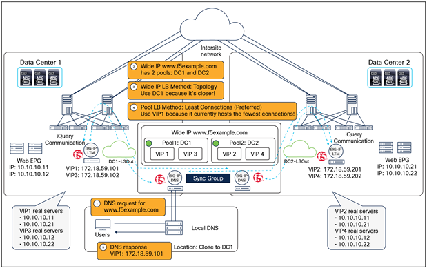
Example of F5 BIG-IP DNS deployment
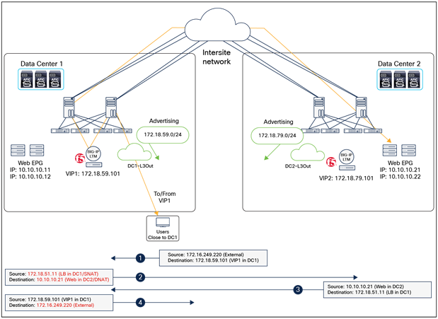
The communication between the external network and an internal Web EPG contains two main parts: one is between the external network and the VIP (the front-end connection) and the other one is between the BIG-IP LTM and the real server in the Web EPG (the back-end connection).
Figure 23 and the steps below explain inbound traffic flow with SNAT being enabled on the BIG-IP LTM.
1. BIG-IP DNS responds to the DNS request with the selected VIP based on the tiered global server load-balancing decision (Figure 22).
2. External client sends traffic destined to the VIP address received in the DNS response. Based on the routing decision, the traffic will arrive at the local L3Out connection in one of the data centers and then will get forwarded to the BIG-IP LTM that owns the VIP. PBR is not required as the destination IP is the VIP owned by the BIG-IP LTM.
3. Once the BIG-IP LTM receives the traffic, it changes the destination IP to one of the real servers that is associated to the VIP. Since SNAT is enabled, the BIG-IP LTM also translates the source IP to the SNAT IP owned by itself and assigned to its internal interface.
4. Next, the traffic is forwarded to the selected real server.
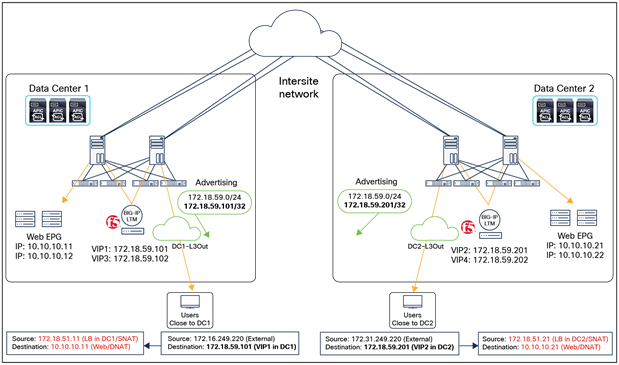
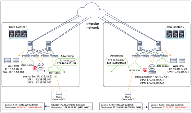
BIG-IP LTM with SNAT inbound traffic flows (optimized)
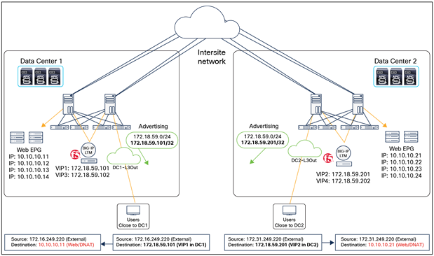
In the specific example shown in the figure above, the ingress traffic path is optimized by advertising host-route information to the external network. By advertising /32 VIP host routes, the traffic sourced from the external client and destined to VIP1 is steered toward DC1, while the traffic destined to VIP2 is going directly toward DC2. For more information on the host-route advertisement feature for ingress traffic optimization, please refer to: https://www.cisco.com/c/en/us/solutions/collateral/data-center-virtualization/application-centric-infrastructure/white-paper-c11-739609.html.
Figure 24 and the steps below explain outbound traffic flow (the return traffic). The real server sends traffic destined to the SNAT IP that is owned by the BIG-IP LTM; thus, PBR is not required to steer traffic back to the BIG-IP LTM.
1. The real server in the Web EPG sends traffic back to the BIG-IP LTM (SNAT IP address).
2. The same BIG-IP LTM receives traffic from the real server and changes the source IP and destination IP. The source IP becomes the VIP, and the destination IP becomes the external client IP.
3. The traffic is sent back to the ACI fabric and forwarded toward the external client through a local L3Out connection.
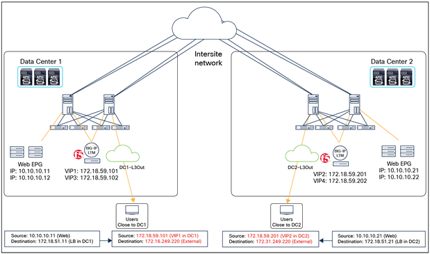
BIG-IP LTM with SNAT outbound traffic flows
As an alternative to the host-route advertisement used in Figure 23, another way to avoid suboptimal inbound traffic is to deploy unique VIP subnets on the BIG-IP LTM in each data center from different BDs (or different IP subnets under the same BD). Note that the use of different BDs does not work with a service graph because a service graph requires a stretched service BD across sites. Thus, with a service graph, multiple IP subnets in the same service BD needs to be configured, so that a unique VIP subnet can be used on the BIG-IP LTM in each data center.
The figure below illustrates an example using different BDs with SNAT instead of a service graph PBR. The service BDs are not stretched, and each BIG-IP LTM pair has a unique VIP address in a different service BD. With that, suboptimal traffic in the ingress direction (which is from the external client to the VIP of the BIG-IP LTM) is avoided without the need to advertise the host-route because the VIP addresses are in different subnet ranges, and each specific IP subnet is only advertised out of the local L3Out for the site in which it is defined.
Note: The inbound traffic optimization design is also applicable to other use cases: ACI Fabric as default gateway with PBR for return traffic, BIG-IP LTM as default gateway without SNAT or PBR and ACI fabric as default gateway (VRF sandwich) without SNAT or PBR.
BIG-IP LTM with SNAT inbound and outbound traffic flows (unique VIP subnet in each site)
This design option with SNAT allows a VIP to include real servers in different sites as well. This is because the return traffic will use the connectivity through the Intersite network to go back to the SNAT IP owned by the BIG-IP LTM that hosts the VIP regardless of the real servers’ locations. Hence, it gives the flexibility to provide redundancy at the server level, though the traffic path may not be optimized (Figure 26).
BIG-IP LTM with SNAT inbound and outbound traffic flows with VIP and real servers in different data centers
Highlights of key characteristics of this design are the following:
● SNAT is used on the BIG-IP LTM.
● PBR is not required since SNAT is used to ensure that both incoming and returning traffic go through the same BIG-IP LTM.
● When a service graph is used, the service BD must be stretched across sites, which means the BIG-IP interfaces (or self IPs) at different data centers must be in the same bridge domain. The bridge domain can contain more than one subnet if needed. One contract is used: a contract between the L3Out EPG and the Web EPG with a BIG-IP LTM service graph. There is no need to create EPGs for the BIG-IP LTM external and internal interfaces by users because the EPGs for the service device and required security rules (which are called zoning-rules in ACI) are created automatically as part of service graph deployment.
● When a service graph is not used, the service BD does not need to be stretched across sites, which means the BIG-IP interfaces (or self IPs) at different data centers can be in different bridge domains. Two contracts are used: one contract is between the L3Out EPG and the BIG-IP LTM EPG for its external interface, and the other contract is between the other BIG-IP LTM EPG for its internal interface and the Web EPG.
● VIP and its real servers can be deployed in different data centers.
ACI fabric as default gateway with PBR for return traffic
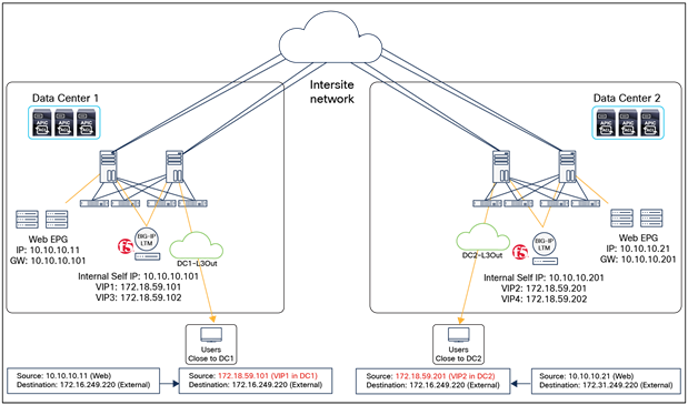
The figure below illustrates an example of a Cisco ACI network design for north-south routed BIG-IP LTM insertion without SNAT. In this example, the ACI fabric is the default gateway of the real servers. Since SNAT is not used, PBR is required for return traffic so that the traffic sourced from the real servers will return to the client through the same BIG-IP LTM (deployed in the same data center). A service graph is mandatory for PBR and because service graph is used, the service BD must be stretched across sites, which means the BIG-IP interfaces (or self IPs) in different data centers must be part of the same service BD. A contract associated with a BIG-IP LTM service graph is required between the L3Out EPG (connecting to the external clients) and the Web EPG. The endpoints in the Web EPG are real servers associated to the VIP of the BIG-IP LTM. The assumption here is that each BIG-IP LTM HA pair in each data center has been assigned a unique VIP address that is part of the same service BD.
Example of a north-south BIG-IP LTM without SNAT design
Figures 28, 29, and 30 show an example of traffic flow including a DNS request and response using BIG-IP DNS. In this example, DC1 VIP1 and VIP3 belong to pool 1 while DC2 VIP2 and VIP4 belong to pool 2 for the same wide IP (FQDN) www.f5example.com. BIG-IP DNSs and BIG-IP LTMs communicate with each other using iQuery through the L3Out for information exchange.
The DNS request and response behavior is the same as described in a previous example (see Figure 22), except that this design requires the VIP and its real servers to be part of the same site. To review the DNS workflow, please refer to the previous DNS deployment example discussion.

Example of F5 BIG-IP DNS deployment
The communication between the external network and an internal Web EPG contains two main parts: one is between the external network and the VIP (the front-end connection) and the other one is between the BIG-IP LTM and the real server in the Web EPG (the back-end connection).
Figure 29 and the steps below explain the inbound traffic flow.
1. BIG-IP DNS responds to the DNS request with the selected VIP based on the tiered global server load-balancing decision (Figure 28).
2. The external client sends traffic destined to the VIP address specified in the DNS response. Based on the routing decision, the traffic will arrive at the local L3Out connection in one of the data centers and then will get forwarded to the BIG-IP LTM that owns the VIP. PBR is not required as the destination IP is the VIP owned by the BIG-IP LTM.
3. Once the BIG-IP LTM receives the traffic, it changes the destination IP to one of the real servers that is associated to the VIP. Since SNAT is not enabled, the BIG-IP LTM leaves the source IP untouched and forwards the traffic back into the fabric.
4. Next, the traffic is forwarded to the selected real server that must be part of the same site.
BIG-IP LTM without SNAT inbound traffic flows (north-south)
In this example, the ingress traffic path is optimized by advertising host-route information to the external network as in the example presented in the previous section. To review the ingress traffic path optimization, please refer to the explanations of Figure 23 and Figure 25 in the previous section.
Figure 29 and the steps below explain the outbound traffic flow (the return traffic). The real server sends traffic back to the original external client’s IP address. Thus, PBR is required to steer the return traffic back to the same BIG-IP LTM that handled the incoming flow. Otherwise, the external client would receive the traffic with the source IP of the real server instead of the VIP, and the traffic will be dropped because the external client did not initiate traffic to the real server IP.
1. The real server in the Web EPG sends the traffic back to the external client. The PBR policy is always applied on the compute leaf node where the web endpoint is connected, which means that the return traffic is steered toward the same BIG-IP LTM, because the VIP and the real server must be part of the same site when PBR is used.
2. The same BIG-IP LTM receives traffic from the real server and changes the source IP only to match the locally defined VIP.
3. The traffic is sent back to the ACI fabric and will be forwarded toward the external client through a local L3Out connection.
BIG-IP LTM without SNAT outbound traffic flows (north-south)
Unlike the previous design option with SNAT, the VIP and its associated real servers must be part of the same site when PBR is used in an ACI Multi-Site deployment. This is because the PBR policy is always applied on the compute leaf node where the EPG for the real servers (the Web EPG in this example) is deployed. In an ACI Multi-Site design, a PBR policy can only redirect traffic to a PBR destination that is part of the same site; hence, to ensure that the return traffic is steered toward the same BIG-IP LTM that handled the incoming flow, the BIG-IP LTM owning the VIP and the real servers must be connected in the same site.
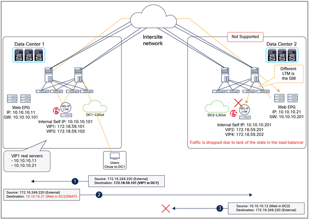
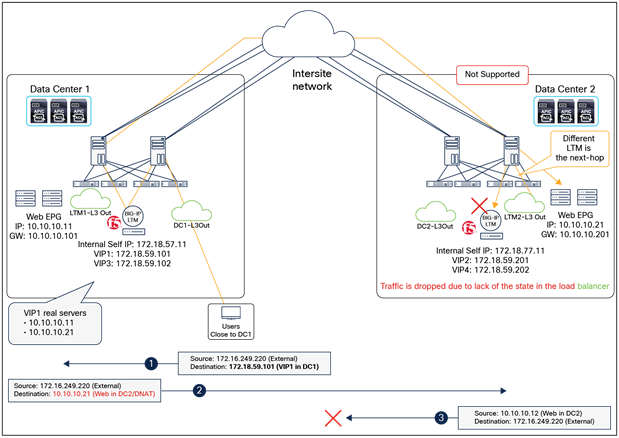
The figure below illustrates an unsupported design where the VIP and its real servers are in different sites: VIP1 is in Data Center 1 and the real server is in Data Center 2 in this case. The return traffic from the real server in Data Center 2 will be redirected to the local BIG-IP LTM that will drop the traffic because of a lack of connection state (that is, because it did not handle the inbound flow).
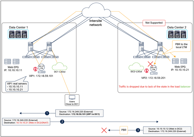
Unsupported example: BIG-IP LTM without SNAT outbound traffic flows (north-south) with the VIP and its real server in different sites
Note: When PBR is used in ACI Multi-Pod, the recommended approach is the same as in ACI Multi-Site: the VIP and its associated real servers must be in the same data centers, and location-based PBR must be enabled, so that the compute leaf node where the real server is connected will select the local PBR destination, to avoid asymmetric load-balancer insertion. For more information on location-based PBR for ACI Multi-Pod, please refer to: https://www.cisco.com/c/en/us/solutions/collateral/data-center-virtualization/application-centric-infrastructure/white-paper-c11-739971.html#LocationbasedPBR.
Highlights of the key characteristics of this design are the following ones:
● SNAT is not used on the BIG-IP LTM.
● PBR is used to steer the return traffic (sourced from the real servers to the original external clients) toward the same BIG-IP LTM that handled the inbound flow (location-based PBR needs to be enabled in the case of ACI Multi-Pod).
● VIP and its real servers must be deployed in the same data center.
● Because a service graph is mandatory to use PBR, the service BD must be stretched, which means the BIG-IP interfaces (or self IPs) at different data centers must be in the same bridge domain. The bridge domain can contain more than one subnet if needed.
● One contract is used: a contract between the L3Out EPG and the Web EPG with a BIG-IP LTM service graph. There is no need to create EPGs for the BIG-IP LTM external and internal interfaces by users because the EPGs for the service device and required security rules (which are called zoning-rules in ACI) are created automatically as part of service graph deployment.
BIG-IP LTM as default gateway without SNAT or PBR
The figure below illustrates an example of a Cisco ACI network design for north-south routed BIG-IP LTM insertion without SNAT or PBR. In this example, the BIG-IP LTM is the default gateway of the real servers. Since the BIG-IP LTM is in the traffic path based on routing, both directions of traffic will always be forced to go through the same BIG-IP LTM and neither SNAT nor PBR is required.
A service graph is not mandatory in this design option. If a service graph is not used, two contracts are required: one contract is between the L3Out EPG and the BIG-IP LTM EPG for its external interface; and another contract between the BIG-IP LTM EPG for its internal interface and Web EPG. The endpoints in the Web EPG are real servers associated to the VIP of the BIG-IP LTM, and the assumption here is that the internal interfaces of the BIG-IP LTM HA pairs and the Web EPG are in the same BD because the BIG-IP LTM is the default gateway of the real servers. Each BIG-IP LTM HA pair in each data center has assigned a unique VIP address that is in the same stretched service BD, though the use of different service BDs is also possible. In this example, the service BD, the Web BD, and the L3Out are defined in the same VRF.
Example of a north-south BIG-IP LTM as gateway without SNAT or PBR
Figures 33, 34, and 35 show an example of a traffic flow including a DNS request and response using BIG-IP DNS. In this example, DC1 VIP1 and VIP3 belong to pool1 while DC2 VIP2 and VIP4 belong to pool2 for the same wide IP (FQDN) www.f5example.com. BIG-IP DNSs and BIG-IP LTMs communicate with each other using iQuery through the L3Out for information exchange.
The key design consideration is that the real servers must have proper default gateway configurations to make sure the incoming traffic and the return traffic go through the same BIG-IP LTM. In this example, the real servers in Data Center 1 uses 10.10.10.101 (BIG-IP LTM in Data Center 1) as the default gateway, whereas the real servers in Data Center 2 use 10.10.10.201 (BIG-IP LTM in Data Center 2) as the default gateway.
The DNS request and response behavior is the same as described in the previous example (Figure 22). To review the DNS workflow, please refer the previous DNS deployment example discussion.
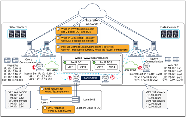
Example of F5 BIG-IP DNS deployment
The communication between the external network and an internal Web EPG contains two main parts: one is between the external network and the VIP (the front-end connection), and the other one is between the BIG-IP LTM and the real server in the Web EPG (the backend connection).
Figure 34 and the steps below explain the inbound traffic flow:
1. BIG-IP DNS responds to the DNS request with the selected VIP based on the tiered global server load-balancing decision (Figure 33).
2. The external client sends traffic destined to the VIP address specified in the DNS response. Based on the routing decision, the traffic will arrive at the local L3Out connection in one of the data centers and then will be forwarded to the BIG-IP LTM that owns the VIP. PBR is not required because the destination IP is the VIP owned by the BIG-IP LTM.
3. Once the BIG-IP LTM receives the traffic, it changes the destination IP to one of the real servers that is associated to the VIP. Since SNAT is not enabled, the BIG-IP LTM leaves the source IP untouched and forwards the traffic back into the fabric.
4. Next, the traffic is forwarded to the selected real server that should use the BIG-IP LTM as the default gateway; otherwise, an asymmetric load-balancer insertion may happen.

BIG-IP LTM as the gateway for inbound traffic flows (north-south)
In this example, the ingress traffic path is optimized by advertising host-route information toward the external network, as in the case for the example explained in the previous section. To review the ingress traffic path optimization, please refer the explanations of Figure 23 and Figure 25 in the previous section.
Figure 35 and the steps below explain the outbound traffic flow (the return traffic). The real server uses the BIG-IP LTM as the default gateway; thus, neither SNAT nor PBR is required to steer traffic back to the BIG-IP LTM.
1. The real server in the Web EPG sends traffic back to the same BIG-IP LTM because it is the default gateway.
2. The same BIG-IP LTM receives traffic from the real server and changes the source IP only to match the locally defined VIP.
3. The traffic is sent back to the ACI fabric and will be forwarded to the external client through a local L3Out connection.
BIG-IP LTM as the gateway for outbound traffic flows (north-south)
In this design option, it is important to make sure that the VIP and the gateway of its associated real servers are on the same BIG-IP LTM. Otherwise, asymmetric routing will happen, and the traffic will be dropped. The figure below illustrates an unsupported design where the VIP and the gateway of its associated real servers are NOT on the same BIG-IP LTM: VIP1 is in Data Center 1, and the default gateway of the real server is in Data Center 2. The return traffic from the real server in Data Center 2 will go to the local BIG-IP LTM, which drops the traffic because of lack of a connection state.
BIG-IP LTM as gateway without SNAT or PBR inbound and outbound traffic flows, where the VIP and the real server's gateway are on different BIG-IP LTMs (north-south)
Highlights of the key characteristics of this design are the following:
● Neither SNAT nor PBR is required.
● A BIG-IP LTM is the gateway for the real servers.
● VIP and its real servers’ gateway must be defined on the same BIG-IP LTM.
● A service graph is not mandatory.
● When a service graph is used, the service BD must be stretched across sites, which means the BIG-IP interfaces (or self IPs) at different data centers must be in the same bridge domain. The bridge domain can contain more than one subnet if needed. One contract is used: a contract between the L3Out EPG and the Web EPG with a BIG-IP LTM service graph. There is no need to create EPGs for the BIG-IP LTM external and internal interfaces by users because the EPGs for the service device and required security rules (which are called zoning-rules in ACI) are created automatically as part of service graph deployment.
● When a service graph is not used, the service BD does not need to be stretched across sites, which means the BIG-IP interfaces (or self IPs) at different data centers can be in different bridge domains. Two contracts are used: one contract is between the L3Out EPG and the BIG-IP LTM EPG for its external interface; and the other contract is between the other BIG-IP LTM EPG for its internal interface and the Web EPG.
ACI fabric as default gateway (VRF sandwich) without SNAT or PBR
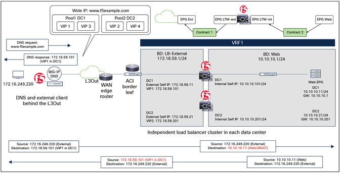
The figure below illustrates another Cisco ACI network design example for north-south routed BIG-IP LTM insertion without SNAT or PBR. In this design option, the ACI fabric is the default gateway of the real servers, and the BIG-IP LTM is inserted in line in the data path by using another L3Out for the internal interface of the BIG-IP LTM, an option usually referred to as a “VRF sandwich.” Since the BIG-IP LTM is in the traffic path based on routing, both directions of the traffic will flow through the same BIG-IP LTM, and neither SNAT nor PBR is required.
A service graph cannot be used in this design option because the use of L3Out for the service device interface in service graph is not available on Nexus® Dashboard Orchestrator (NDO) as of release 4.1. Because a service graph is not used, two contracts are required: one contract is between the L3Out EPG for the external network and the BIG-IP LTM EPG in the external VRF (VRF1); and the other contract is between the L3Out EPG for the BIG-IP LTM internal interface and the Web EPG in the internal VRF (VRF2). The endpoints in the Web EPG are real servers associated to the VIP of the BIG-IP LTM. Each BIG-IP LTM HA pair in each data center has assigned a unique VIP address that is in the same BD, though the use of different service BDs is also possible.
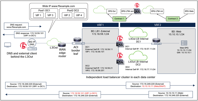
Example of a north-south BIG-IP LTM as gateway without SNAT or PBR (VRF sandwich)
This design has two important considerations:
● The internal interface of the BIG-IP LTM is connected to an L3Out defined in each site. Because an L3Out local interface subnet (L3Out BD) cannot be stretched across sites, each BIG-IP LTM HA pair at each data center uses a unique internal interface IP address, whereas its external interface can be in the same BD as illustrated in Figure 37.
● The ACI fabric must have a route to the external network in the internal VRF (VRF2) pointing to the same BIG-IP LTM as next hop (that is, the same BIG-IP LTM owning the VIP). This is because the return traffic from the real server destined to the external network arrives on the ACI fabric that is the default gateway of the real servers, and is then forwarded to the routing next hop based on the internal VRF (VRF2) routing table. If the next-hop is a different BIG-IP LTM that does not have connection state information, the traffic is dropped. An example will be explained later in this section (Figure 41).
Figures 38, 39, and 40 show an example of a traffic flow including a DNS request and a response using BIG-IP DNS. In this example, DC1 VIP1 and VIP3 belong to pool1 while DC2 VIP2 and VIP4 belong to pool2 for the same Wide IP (FQDN) www.f5example.com. BIG-IP DNSs and BIG-IP LTMs communicate with each other using iQuery through the L3Out for information exchange.
The DNS request and response behavior is the same as described in a previous example (Figure 22). To review the DNS workflow, please refer the previous DNS deployment example discussion.

Example of a BIG-IP DNS deployment
The communication between the external network and an internal Web EPG contains two main parts: one is between the external network and the VIP (the frontend connection) and the other one is between the internal interface of the BIG-IP LTM and the real server in the Web EPG (the backend connection).
Figure 39 and the steps below explain the inbound traffic flow:
1. BIG-IP DNS responds to the DNS request with the selected VIP based on the tiered global server load-balancing decision (Figure 38).
2. The external client sends traffic destined to the VIP address specified in the DNS response. Based on the routing decision, the traffic will arrive at the local L3Out connection in one of the data centers and then will get forwarded to the BIG-IP LTM that owns the VIP. PBR is not required because the destination IP is the VIP owned by the BIG-IP LTM. This communication is handled in the context of the external VRF (VRF1) routing domain.
3. Once the BIG-IP LTM receives the traffic, it changes the destination IP to one of the real servers that is associated to the VIP. Since SNAT is not enabled, the BIG-IP LTM leaves the source IP untouched and forwards the traffic to the fabric.
4. Next, the traffic is forwarded to the selected real server in the same data center. This communication is handled in the context of the internal VRF (VRF2) routing domain.
ACI fabric as the default gateway without SNAT or PBR (VRF sandwich) for inbound traffic flows (north-south)
In this example, the ingress traffic path is optimized by advertising host-route information toward the external network as in the example explained in the previous section. To review the ingress traffic path optimization, please refer the explanations of Figure 23 and Figure 25 in the previous section.
Figure 40 and the steps below explain the outbound traffic flow (the return traffic). The BIG-IP LTM is inserted based on routing; thus, neither SNAT nor PBR is required to steer traffic back to the BIG-IP LTM.
1. The real server in the Web EPG sends traffic to the ACI fabric because the ACI fabric is its gateway.
2. As the ACI fabric has a route to the external client through the local BIG-IP LTM, the traffic is forwarded according to the fabric’s routing table to the same BIG-IP LTM that handled the inbound flow.
3. The same BIG-IP LTM receives traffic from the real server and changes the source IP only to match the locally defined VIP.
4. The traffic is then sent back into the fabric and forwarded to the external client through a local L3Out connection.
ACI fabric as the default gateway without SNAT or PBR (VRF sandwich) for outbound traffic flows (north-south)
In this design option, it is important to make sure that the VIP and the associated real servers are in the same site. Otherwise, asymmetric routing will happen, and the traffic will be dropped. The figure below illustrates an unsupported design where the VIP and its associated real servers are NOT on the same BIG-IP LTM: VIP1 is in Data Center 1, and the real server is in Data Center 2. The return traffic from the real server in Data Center 2 will go to the local BIG-IP LTM based on routing (the local L3Out is Preferred, to reach the same external prefix by default), which drops the traffic because of lack of a connection state.
ACI fabric as the default gateway without SNAT or PBR for inbound and outbound traffic flows where the VIP and the ACI external route’s next hops are on different BIG-IP LTMs (north-south)
Highlights of the key characteristics of this design are the following:
● Neither SNAT nor PBR is required.
● This is the traditional VRF sandwich design, with 2 VRFs: one VRF is for internal and the other VRF is for external. All inter-VRF traffic is steered through the BIG-IP LTM based on routing.
● VIP and its real servers must be part of the same site.
● ACI fabric is the default gateway of the real servers.
● The ACI fabric’s internal VRF must have a route to the external network through the BIG-IP LTM.
● Because an L3Out cannot be stretched across sites, an L3Out for the internal interface of the BIG-IP LTM is defined in each site.
● A service graph cannot be used as of Nexus Dashboard Orchestrator Release 4.1.
● Because a service graph is not used, the service BD for the external interface of the BIG-IP LTM does not need to be stretched across sites, which means the BIG-IP external interfaces (or self IPs) at different data centers can be in different bridge domains. Two contracts are used: one contract is between the L3Out EPG for the external network and the BIG-IP LTM EPG, and the other contract is between the internal interface of the BIG-IP LTM EPG and the Web EPG.
Cisco ACI and F5 BIG-IP Integration: https://f5.com/cisco
F5 IBG-IP DNS: https://www.f5.com/products/big-ip-services/big-ip-dns
F5 BIG-IP Local Traffic Manager (LTM): https://www.f5.com/products/big-ip-services/local-traffic-manager