Deploy Cisco UCS C240 M5 Rack Servers with Intel Optane Persistent Memory for Enterprise End-User Computing
Available Languages
Bias-Free Language
The documentation set for this product strives to use bias-free language. For the purposes of this documentation set, bias-free is defined as language that does not imply discrimination based on age, disability, gender, racial identity, ethnic identity, sexual orientation, socioeconomic status, and intersectionality. Exceptions may be present in the documentation due to language that is hardcoded in the user interfaces of the product software, language used based on RFP documentation, or language that is used by a referenced third-party product. Learn more about how Cisco is using Inclusive Language.
Organizations increasingly are adopting hybrid cloud computing environments, and Cisco architectures are at the center of on-premises infrastructure. With new memory technologies available today such as Intel’s PMEM, the question for IT management is often “Is PMEM right for the Virtual Desktop Infrastructure (VDI) deployment? This document describes the design and testing of a solution using Cisco UCS® Manager Release 4.1(2), Cisco UCS C240 M5 Rack Servers with Intel® Optane® persistent memory, VMware vSphere 7.0, VMware Horizon 7.12, Citrix Virtual Apps and Desktops 1912 LTSR, and a “white box” storage array. Cisco UCS Manager 4.1(2) provides consolidated support for all current Cisco UCS fabric interconnect models: Cisco UCS 6200, 6300, and 6400 Series Fabric Interconnects; and Cisco UCS 6324 Fabric Interconnects (Cisco UCS Mini). It also provides support for Cisco UCS 2200, 2300, and 2400 Series Fabric Extenders; Cisco UCS B-Series Blade Servers; and Cisco UCS C-Series Rack Servers. The solution also includes the Cisco Intersight™ management platform.
The results of the study reported in this document show that the traditional Cisco UCS server configuration with dynamic RAM (DRAM) is comparable to a configuration with Intel Optane persistent memory. With both Citrix and VMware Horizon, virtual desktop infrastructure (VDI) workloads performed quite well with Intel’s persistent memory. By using persistent memory (PMEM) instead of DRAM in VDI environments, organizations may achieve a lower-cost solution.
● For VDI configurations greater than 1 TB per server, customers can achieve a higher return on investment (ROI) by using PMEM, without sacrificing performance.
● Incorporating PMEM will not by itself negatively affect performance.
● Performance results were the same across Citrix and VMware Horizon–based solutions.
This section describes the Cisco components used in the architecture.
Cisco Intersight platform
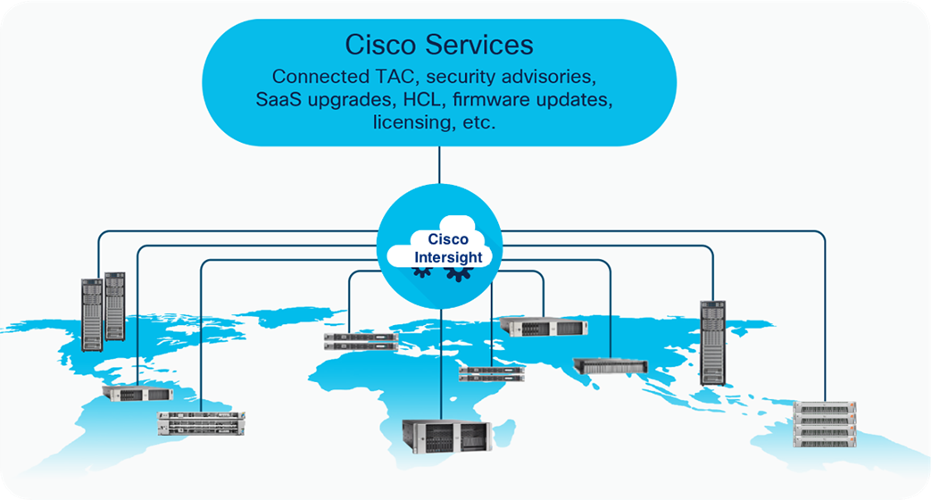
The Cisco Intersight platform is a software-as-a-service (SaaS) infrastructure lifecycle management platform that delivers simplified configuration, deployment, maintenance, and support. With the Cisco Intersight platform, customers get all the benefits of SaaS delivery and the full lifecycle management of Cisco Intersight connected distributed servers and third-party storage systems across data centers, remote sites, branch offices, and edge environments (Figure 1).
The Cisco Intersight platform is designed to be modular, so customers can adopt services based on their individual requirements. The platform significantly simplifies IT operations by bridging applications with infrastructure, providing visibility and management from bare-metal servers and hypervisors to serverless applications, and thereby reducing costs and mitigating risk. This unified SaaS platform uses a unified open API that natively integrates with third-party platforms and tools. .
Cisco Intersight overview
The main benefits of Cisco Intersight infrastructure services are summarized here:
● Simplify daily operations by automating many daily manual tasks.
● Combine the convenience of a SaaS platform with the capability to connect from anywhere and manage infrastructure through a browser or mobile app.
● Stay ahead of problems and accelerate trouble resolution through advanced support capabilities.
● Gain global visibility of infrastructure health and status along with advanced management and support capabilities.
● Upgrade to add workload optimization and Kubernetes services when needed.
Cisco UCS Manager provides unified, embedded management for all software and hardware components of the Cisco Unified Computing System™ (Cisco UCS) through an intuitive GUI, a command-line interface (CLI), and an XML API. The manager provides a unified management domain with centralized management capabilities and can control multiple chassis and thousands of virtual machines.
Cisco UCS is a next-generation data center platform that unites computing, networking, and storage access. The platform, optimized for virtual environments, is designed using open industry-standard technologies and aims to reduce total cost of ownership (TCO) and increase business agility. The system integrates a low-latency lossless 25 Gigabit Ethernet unified network fabric with enterprise-class x86-architecture servers. It is an integrated, scalable, multichassis platform in which all resources participate in a unified management domain.
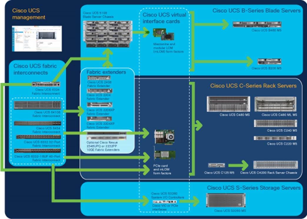
Cisco Unified Computing System components
The main components of Cisco UCS (Figure 2) are as follows:
● Computing: The system is based on an entirely new class of computing system that incorporates blade servers based on Intel® Xeon® Scalable family processors.
● Network: The system is integrated on a low-latency, lossless, 25 Gigabit Ethernet unified network fabric. This network foundation consolidates LANs, SANs, and high-performance computing (HPC) networks, which are separate networks today. The unified fabric lowers costs by reducing the number of network adapters, switches, and cables needed, and by decreasing the power and cooling requirements.
● Virtualization: The system unleashes the full potential of virtualization by enhancing the scalability, performance, and operational control of virtual environments. Cisco security, policy enforcement, and diagnostic features are now extended into virtualized environments to better support changing business and IT requirements.
● Storage access: The system provides consolidated access to local storage, SAN storage, and network-attached storage (NAS) over the unified fabric. With storage access unified, Cisco UCS can access storage over Ethernet, Fibre Channel, Fibre Channel over Ethernet (FCoE), and Small Computer System Interface over IP (iSCSI) protocols. This capability provides customers with choice for storage access and investment protection. In addition, server administrators can pre-assign storage-access policies for system connectivity to storage resources, simplifying storage connectivity and management and helping increase productivity.
● Management: Cisco UCS uniquely integrates all system components, enabling the entire solution to be managed as a single entity by Cisco UCS Manager. Cisco UCS Manager has an intuitive GUI, a CLI, and a robust API for managing all system configuration processes and operations.
Cisco data center overview
Cisco UCS is designed to deliver these main benefits:
● Reduced TCO and increased business agility
● Increased IT staff productivity through just-in-time provisioning and mobility support
● A cohesive, integrated system that unifies the technology in the data center; the system is managed, serviced, and tested as a whole
● Scalability through a design for hundreds of discrete servers and thousands of virtual machines and the capability to scale I/O bandwidth to match demand
● Industry standards supported by a partner ecosystem of industry leaders
Cisco UCS Manager provides unified, embedded management of all software and hardware components of Cisco UCS across multiple chassis, rack servers, and thousands of virtual machines. Cisco UCS Manager manages Cisco UCS as a single entity through an intuitive GUI, a CLI, or an XML API for comprehensive access to all Cisco UCS Manager functions.
Cisco UCS 6400 Series Fabric Interconnects
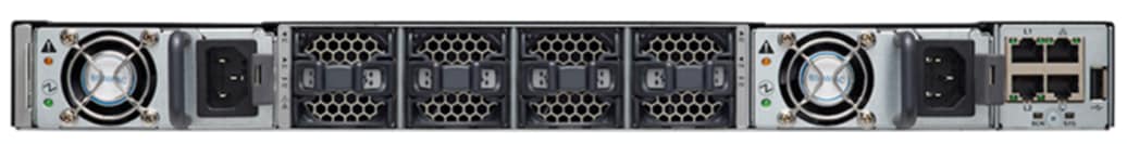
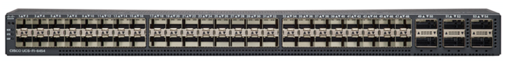
Cisco UCS 6400 Series Fabric Interconnects (Figure 3 and Figure 4) are a core part of Cisco UCS, providing both network connectivity and management capabilities for the system. The Cisco UCS 6400 Series offers line-rate, low-latency, lossless 10, 25, 40, and 100 Gigabit Ethernet; FCoE; and Fibre Channel functions.
The Cisco UCS 6400 Series provides the management and communication backbone for the Cisco UCS B-Series Blade Servers, Cisco UCS 5108 Blade Server Chassis, Cisco UCS managed Cisco UCS C-Series Rack Servers, and Cisco UCS S-Series Storage Servers. All servers attached to a Cisco UCS 6400 Series Fabric Interconnect become part of a single, highly available management domain. In addition, by supporting a unified fabric, the Cisco UCS 6400 Series Fabric Interconnect provides both LAN and SAN connectivity for all servers within its domain.
From a networking perspective, the Cisco UCS 6400 Series uses a cut-through architecture, supporting deterministic, low-latency, line-rate 10, 25, 40, and 100 Gigabit Ethernet ports. It provides switching capacity of 3.82 Tbps for the Cisco UCS 6454 Fabric Interconnect, 7.42 Tbps for the Cisco UCS 64108 Fabric Interconnect, and 200 Gigabit Ethernet bandwidth between the Cisco UCS 6400 Series Fabric Interconnect and the Cisco UCS 2408 I/O module (IOM) for each Cisco UCS 5108 Blade Server Chassis, independent of packet size and enabled services. The product family supports Cisco low-latency, lossless 10, 25, 40, and 100 Gigabit Ethernet unified network fabric capabilities, which increase the reliability, efficiency, and scalability of Ethernet networks. The fabric interconnect supports multiple traffic classes over a lossless Ethernet fabric from the server through the fabric interconnect. Significant TCO savings come from an FCoE-optimized server design in which network interface cards (NICs), host bus adapters (HBAs), cables, and switches can be consolidated.
Cisco UCS 6400 Series Fabric Interconnect: Cisco UCS 6454 front view
Cisco UCS 6400 Series Fabric Interconnect: Cisco UCS 6454 rear view
Cisco UCS C-Series Rack Servers
Cisco UCS C-Series Rack Servers keep pace with Intel Xeon processor innovation by offering the latest processors with increased processor frequencies and improved security and availability features. With the increased performance provided by the Intel Xeon processor Scalable product family, C-Series servers offer an improved price-to-performance ratio. They also extend Cisco UCS innovations to an industry-standard rack-mount form factor, including a standards-based unified network fabric, Cisco® VN-Link virtualization support, and Cisco Extended Memory Technology.
Designed to operate both in standalone environments and as part of Cisco UCS managed configuration, these servers enable organizations to deploy systems incrementally—using as many or as few servers as needed—on a schedule that best meets the organization’s timing and budget. C-Series servers offer investment protection through the capability to deploy them either as standalone servers or as part of Cisco UCS.
One compelling reason that many organizations prefer rack-mount servers is the wide range of I/O options available in the form of PCI Express (PCIe) adapters. C-Series servers support a broad range of I/O options, including interfaces supported by Cisco as well as adapters from third parties.
The Cisco UCS C240 M5 Rack Server (Figure 5) is designed for both performance and expandability over a wide range of storage-intensive infrastructure workloads, from big data to collaboration.
The C240 M5 small form-factor (SFF) server extends the capabilities of the Cisco UCS portfolio in a two-rack-unit (2RU) form factor with the addition of the Intel Xeon processor Scalable family, 24 DIMM slots for 2666-MHz DDR4 DIMMs, and up to 128 GB of capacity, up to 6 PCIe 3.0 slots, and up to 26 internal SFF drives. The C240 M5 SFF server also includes one dedicated internal slot for a 12-Gbps SAS storage controller card. The C240 M5 server includes a dedicated internal modular LAN-on-motherboard (mLOM) slot for installation of a Cisco virtual interface card (VIC) or third-party NIC without consuming a PCI slot, in addition to two 10GBASE-T Intel x550 LOM ports embedded on the motherboard.
In addition, the C240 M5 offers outstanding levels of internal memory and storage expandability with exceptional performance. It offers these features:
● Up to 24 DDR4 DIMMs at speeds up to 2666 MHz for improved performance and lower power consumption
● One or two Intel Xeon processor Scalable family CPUs
● Up to six PCIe 3.0 slots (four full-height, full-length for the graphics processing unit [GPU])
● Six hot-swappable fans for front-to-rear cooling
● Twenty-four SFF front-facing SAS/SATA hard-disk drives (HDDs) or SAS/SATA solid-state disks (SSDs)
● Optionally, up to two front-facing SFF Non-Volatile Memory Express (NVMe) PCIe SSDs (replacing SAS/SATA drives); these drives must be placed in front drive bays 1 and 2 only and are controlled from Riser 2 option C
● Optionally, up to two SFF, rear-facing SAS/SATA HDDs or SSDs or up to two rear-facing SFF NVMe PCIe SSDs; rear-facing SFF NVMe drives are connected from Riser 2, Option B or C
● Support for 12-Gbps SAS drives
● Flexible support on the dedicated mLOM slot on the motherboard, accommodating the following cards:
◦ Cisco VICs
◦ Quad-port Intel i350 1 Gigabit Ethernet RJ-45 mLOM NIC
● Two 1 Gigabit Ethernet embedded LOM ports
● Support for up to two double-wide NVIDIA GPUs, providing a robust graphics experience to more virtual users
● Excellent reliability, availability, and serviceability (RAS) features with tool-free CPU insertion, easy-to-use latching lid, and hot-swappable and hot-pluggable components
● One slot for a micro–Secure Digital (SD) card on PCIe Riser 1 (Options 1 and 1B)
◦ The micro-SD card serves as a dedicated local resource for utilities such as the Cisco Host Upgrade Utility (HUU).
◦ Images can be pulled from a file share (Network File System [NFS] or Common Internet File System [CIFS]) and uploaded to the cards for future use.
● A mini-storage module connector on the motherboard supports either of the following:
◦ An SD card module with two SD card slots (Mixing different-capacity SD cards is not supported.)
◦ An M.2 module with two SATA M.2 SSD slots (Mixing different-capacity M.2 modules is not supported.)
Note: SD cards and M.2 modules cannot be mixed. M.2 does not support RAID-1 with VMware. Only Microsoft Windows and Linux operating systems are supported.
The C240 M5 also increases performance and customer choice over many types of storage-intensive applications such as the following:
● Collaboration
● Small and medium-sized business (SMB) databases
● Big data infrastructure
● Virtualization and consolidation
● Storage servers
● High-performance appliances
The C240 M5 can be deployed as a standalone server or as part of Cisco UCS. Cisco UCS unifies computing, networking, management, virtualization, and storage access into a single integrated architecture that enables end-to-end server visibility, management, and control in both bare-metal and virtualized environments. Within a Cisco UCS deployment, the C240 M5 takes advantage of Cisco’s standards-based unified computing innovations, which significantly reduce customers’ TCO and increase business agility.
For more information about the Cisco UCS C240 M5 Rack Server, see https://www.cisco.com/c/dam/en/us/products/collateral/servers-unified-computing/ucs-c-series-rack-servers/c240m5-sff-specsheet.pdf.
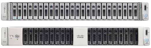
Cisco UCS C240 M5 Rack Server
Cisco UCS VIC 1457
The Cisco UCS VIC 1457 (Figure 6) is a quad-port Small Form-Factor Pluggable 28 (SFP28) mLOM card designed for the M5 generation of Cisco UCS C-Series Rack Servers. The card supports 10- and 25-Gbps Ethernet and FCoE, where the speed of the link is determined by the model of SFP optics or cables used. The card can be configured to use a pair of single links, or optionally to use all four links as a pair of bonded links. The VIC 1457 is used in conjunction with the Cisco UCS 6454 Fabric Interconnect.
The mLOM is used to install a Cisco VIC without consuming a PCIe slot, which provides greater I/O expandability. It incorporates next-generation converged network adapter (CNA) technology from Cisco, providing investment protection for future feature releases. The card enables a policy-based, stateless, agile server infrastructure that can present up to 256 PCIe standards-compliant interfaces to the host, each dynamically configured as either a NIC or an HBA. The personality of the interfaces is set programmatically using the service profile associated with the server. The number, type (NIC or HBA), identity (MAC address and World Wide Name [WWN]), failover policy, adapter settings, bandwidth, and quality-of-service (QoS) policy of the PCIe interfaces are all specified using the service profile.
For more information about the VIC, see https://www.cisco.com/c/en/us/products/collateral/interfaces-modules/unified-computing-system-adapters/datasheet-c78-741130.html.
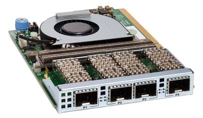
Cisco UCS VIC 1457 CNA
The Cisco Nexus® 93180YC-FX Switch (Figure 7) provides a flexible line-rate Layer 2 and Layer 3 feature set in a compact form factor. Designed with Cisco Cloud Scale technology, it supports highly scalable cloud architectures. With the option to operate in Cisco NX-OS or Cisco Application Centric Infrastructure (Cisco ACI™) mode, it can be deployed across enterprise, service provider, and Web 2.0 data centers.
The 93180YC-FX offers these benefits:
● Architectural flexibility
◦ Top-of-rack (ToR) and middle-of-row (MoR) fiber-based server access connectivity for traditional and leaf-spine architectures
◦ Leaf-node support for Cisco ACI architecture (on the roadmap)
◦ Increased scale and simplified management through Cisco Nexus 2000 Series Fabric Extender support
● Robust feature set
◦ Enhanced Cisco NX-OS Software, designed for performance, resiliency, scalability, manageability, and programmability
◦ Cisco ACI ready infrastructure, helping users take advantage of automated policy-based systems management
◦ Virtual Extensible LAN (VXLAN) routing for network services
◦ Robust traffic-flow telemetry information with line-rate data collection
◦ Real-time buffer utilization per port and per queue, for monitoring traffic microbursts and application traffic patterns
● Highly available and efficient design
◦ High-density, nonblocking architecture
◦ Easy deployment in either a hot-aisle or cold-aisle configuration
◦ Redundant, hot-swappable power supplies and fan trays
● Simplified operations
◦ Power-on autoprovisioning (POAP) support, for simplified software upgrades and configuration file installation
◦ Intelligent API for switch management through remote procedure calls (RPCs), JavaScript Object Notation (JSON), or XML over a HTTP/HTTPS infrastructure
◦ Python scripting for programmatic access to the switch CLI
◦ Hot and cold patching, and online diagnostics
● Investment protection
A Cisco 40 Gigabit Ethernet bidirectional transceiver allows reuse of an existing 10 Gigabit Ethernet multimode cabling plant for 40 Gigabit Ethernet and provides support for 1 and 10 Gigabit Ethernet access connectivity for data centers migrating access switching infrastructure to faster speeds. The switch supports the following:
● 1.8 Tbps of bandwidth in a 1RU form factor
● Forty-eight fixed 1, 10, and 25 Gigabit Ethernet Enhanced SFP (SFP+) ports
● Six fixed 40 and 100 Gigabit Ethernet Quad SFP+ (QSFP+) for uplink connectivity
● Latency of less than 2 microseconds
● Front-to-back or back-to-front airflow configurations
● 1+1 redundant hot-swappable 80 Plus Platinum-certified power supplies
● Hot-swappable 3+1 redundant fan trays
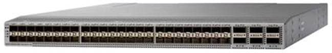
Cisco Nexus 93180YC-FX Switch
This section provides overview of the infrastructure setup, software and hardware requirements, and some of the design details. This section does not discuss the design details and configuration of components such as Cisco Nexus and Cisco MDS 9000 Family switches and storage array systems because their design and configuration conform to various Cisco Validated Designs for converged infrastructure and are covered widely elsewhere. This document focuses on the design elements and performance of the Intel platform for application in VDI environments.
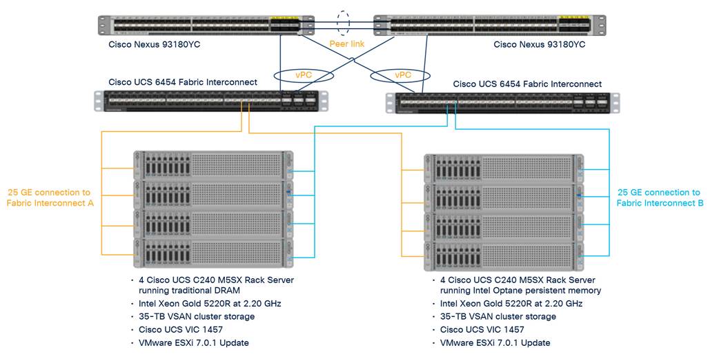
Physical architecture
Components deployed include the following:
● Two Cisco Nexus 93180YC-FX Switches
● Two Cisco UCS 6454 Fabric Interconnects
● Four Cisco UCS C240 M5 Series Rack Servers with 1 TB of DRAM
● Four Cisco UCS C240 M5 Series Rack Servers with 1 TB of Intel Optane persistent memory
● Two separate VSAN clusters for storage
The logical architecture is configured identically in both clusters to directly compare the performance of traditional DRAM to the performance of Intel Optane persistent memory (Figure 9. For desktop virtualization, the deployment includes Citrix 1912 LTSR CU2 running on VMware vSphere ESXi 7.0.1 U1.
The purpose of this design is to compare and contrast DRAM to PMEM in a VDI environment on Cisco UCS servers.
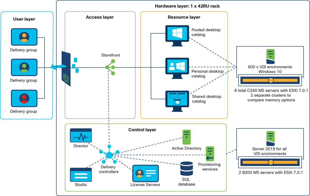
Logical architecture
Table 1 lists the software and firmware versions used in the solution described in this document.
Table 1. Software and firmware versions
| Component |
Version |
| Cisco UCS component firmware |
Bundle Release 4.1(2b) |
| Cisco UCS Manager |
Bundle Release 4.1(2b) |
| Cisco UCS B200 M5 blades |
Bundle Release 4.1(2b) |
| Cisco UCS VIC 1440 |
Bundle Release 4.1(2b) |
| Cisco UCS C240 M5 |
Bundle Release 4.1(2b) |
| Cisco UCS VIC 1457 |
Bundle Release 4.1(2b) |
| VMware vCenter Server Appliance |
Release 7.0.0.10400 |
| VMware vSphere 7. 0.1 U1 |
Release 17325551 |
| Citrix Virtual Apps and Desktops 1912 LTSR CU2 |
Release 1912.2000 |
| Citrix Provisioning Services (PVS) |
Release 1912.2000 |
| Citrix Virtual Desktop Agent (VDA) |
Release 1912.2000 |
| Microsoft FSLogix for profile management |
FSLogix_Apps_2.9.7654.46150 |
Creating Cisco UCS persistent-memory policy
1. In Cisco UCS Manager, choose Servers.
2. Expand Policies > root.
3. Right-click Persistent Memory Policy.
4. Choose Create Persistent Memory Policy.
5. Name the policy Memory-Mode.
6. Under Goals, click Add.
7. Set Memory Mode (%) to 100 and set Persistent Memory Type to App Direct.
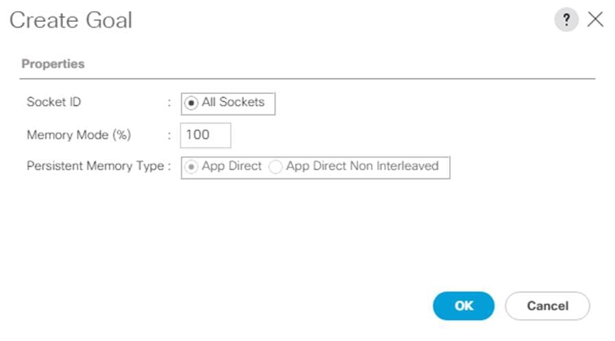
8. Click OK to complete creating the goal.
9. Click OK to complete creating the policy and click OK on the confirmation page.
Getting started with the Cisco Intersight platform
The Cisco Intersight platform provides an integrated and intuitive management experience for resources in the traditional data center and at the edge. With flexible deployment options to address complex security needs, getting started with the Cisco Intersight platform is quick and easy.
To configure the Cisco Intersight platform, follow these steps:
1. If you do not already have a Cisco Intersight account, claim your Cisco UCS deployment in a new account on the Cisco Intersight platform by connecting to https://intersight.com. If you have an existing Cisco Intersight account, connect to https://intersight.com and sign in with your Cisco ID, select the appropriate account, and skip to step 6.
2. Click Create an Account.
3. Sign in with your Cisco ID.
4. Read, scroll through, and accept the End User License Agreement and click Next.
5. Enter an account name and click Create.
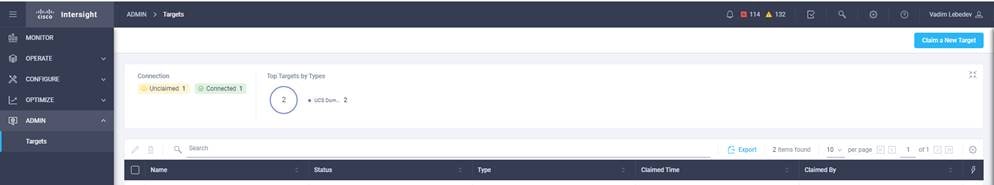
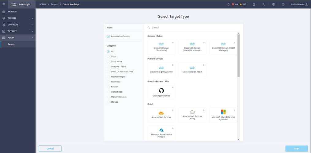
6. Choose ADMIN > Targets. Click Claim a New Target.
7. Select Cisco UCS Domain (UCSM Managed) and click Start.
8. Fill in the Device ID and Claim Code fields and click Claim.
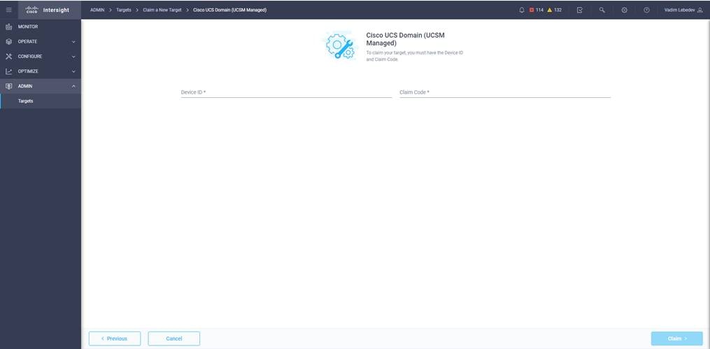
Note: You can obtain the device ID and claim code by connecting to Cisco UCS Manager and choosing Admin > All > Device Connector. The device ID and claim code are on the right.
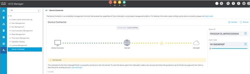
The target will be visible in the list of available targets.
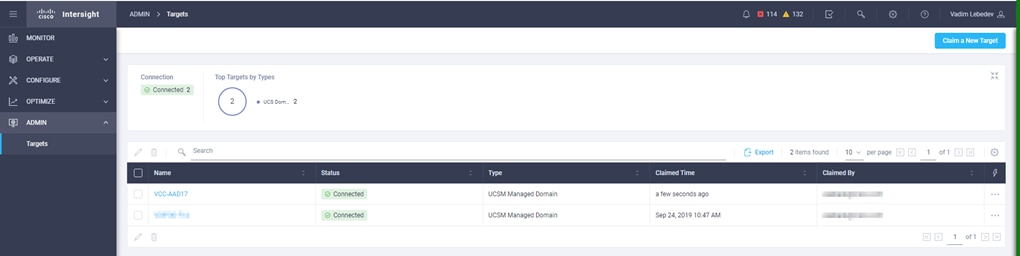
9. From the Cisco Intersight window, click the Settings icon and then click Licensing. If this is a new account, all servers connected to the Cisco UCS domain will appear under the Base license tier. If you have purchased Cisco Intersight licenses and have them in your Cisco Smart Account, click Register and follow the prompts to register this Cisco Intersight account to your Cisco Smart Account. The Cisco Intersight platform also offers a one-time 90-day trial of Premier licensing for new accounts. Click Start Trial and then Start to begin this evaluation. The remainder of this section assumes that you are using Premier licensing.
VDI configuration: Configuring the master target
Virtual machines for the master target must first be installed with the software components needed to build the golden images. Additionally, all available security patches for the Microsoft operating system and Microsoft Office should be installed.
To prepare the master virtual machines, perform these four major steps:
1. Install the operating system and VMware tools.
2. Install the application software.
3. Install the Citrix VDA.
4. Optimize the image with the Citrix OS Optimization Tool.
Note: VMware OSOT, the optimization tool, includes customizable templates to enable or disable Windows system services and features using VMware recommendations and best practices across multiple systems. Because most Windows system services are enabled by default, the optimization tool can be used to easily disable unnecessary services and features to improve performance of your virtual desktops.
Note: The images contain the basic functions needed to run the Login VSI workload.
The master target virtual machine was configured as listed in Table 2.
Table 2. VDI virtual machine configuration
| Configuration |
VDI virtual machines |
| Operating system |
Microsoft Windows 10 64-bit |
| Virtual CPUs (vCPUs) |
2 |
| Memory |
4 GB reserve for all guest memory |
| Network |
VMXNET3 VDI |
| Virtual disk (vDisk) size |
32 GB |
| Additional software used for testing |
Microsoft Office 2016 Login VSI 4.1.40 (Knowledge Worker Workload) |
Testing focused on host memory performance and comparison of traditional DRAM to Intel Optane persistent memory. Testing assessed processing of the virtual desktop lifecycle during desktop boot-up, user logon and virtual desktop acquisition (also referred to as ramp-up,) user workload execution (also referred to as steady state), and user logoff for the VDI session under test. This testing methodology is used in all Cisco Validated Designs for VDI and can be referenced here: https://ucsnav.cisco.com/design-navigator/#/VCC?_k=yur5o2
Test metrics were gathered from the Cisco UCS host and load-generation software to assess the overall success of an individual test cycle.
You can obtain additional information and a free test license at http://www.loginvsi.com.
DRAM cluster test results with Citrix Virtual Apps and Desktops
This section shows the key performance metrics that were captured on the Cisco UCS C240 M5 servers with dual Intel Xeon 5220R processors and 1 TB of 2933-MHz DRAM during cluster testing in the N+1 environment. The cluster testing was performed using Windows 10 64-bit VDI nonpersistent virtual machines (instant clones for VMware Horizon and Citrix PVS for Citrix) with two vCPUs and 4 GB of RAM.
Figure 10 shows the Login VSI data.
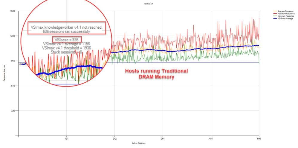
DRAM cluster scale testing for Citrix 1912 LTSR VDI: VSI score
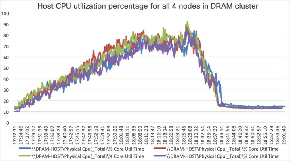
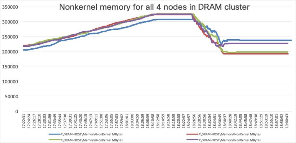
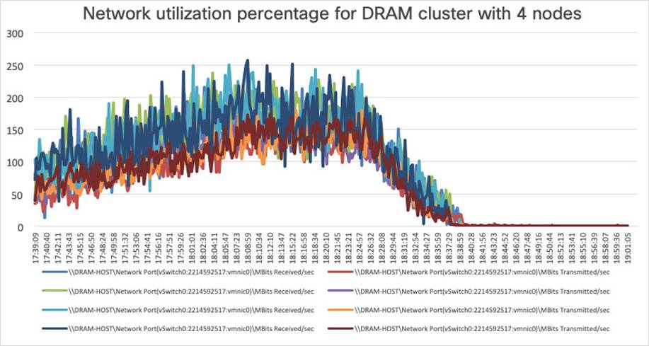
Figure 11, Figure 12, Figure 13, and Figure 14 show performance data for the server running the workload.
DRAM cluster scale testing for Citrix 1912 LTSR VDI: Host CPU utilization
DRAM cluster scale testing for Citrix 1912 LTSR VDI: Host memory utilization
DRAM cluster scale testing for Citrix 1912 LTSR VDI: Host network utilization (received traffic)
DRAM cluster scale testing for Citrix 1912 LTSR VDI: Host network utilization (transmitted traffic)
Intel Optane persistent-memory cluster test results with Citrix Virtual Apps and Desktops
This section shows the key performance metrics that were captured on the Cisco UCS C240 M5 servers with dual Intel Xeon 5220R processors and 1 TB of 2666-MHz PMEM and 384 GB of 2933-MHz DRAM during cluster testing in the N+1 environment. The cluster testing was performing using Windows 10 64-bit VDI nonpersistent virtual machines (instant clones for VMware Horizon and Citrix PVS for Citrix) with 2 vCPUs and 4 GB of RAM.
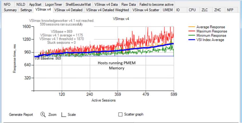
Figure 15 shows the Login VSI data.
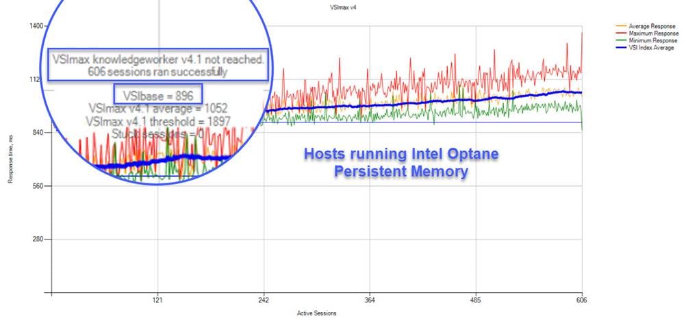
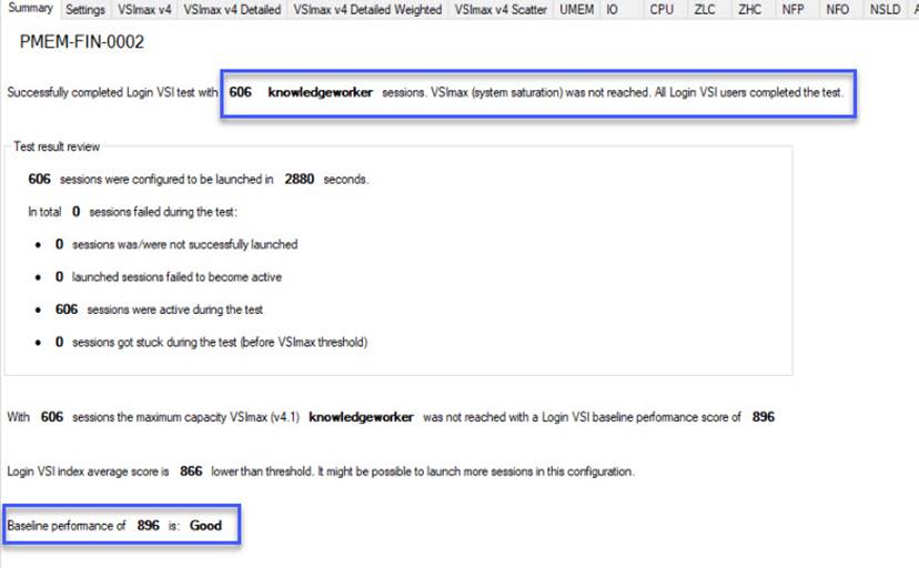
Intel Optane persistent-memory cluster scale testing for Citrix 1912 LTSR VDI: VSI score
Figure 16, Figure 17, Figure 18, and Figure 19 show performance data for the server running the workload.
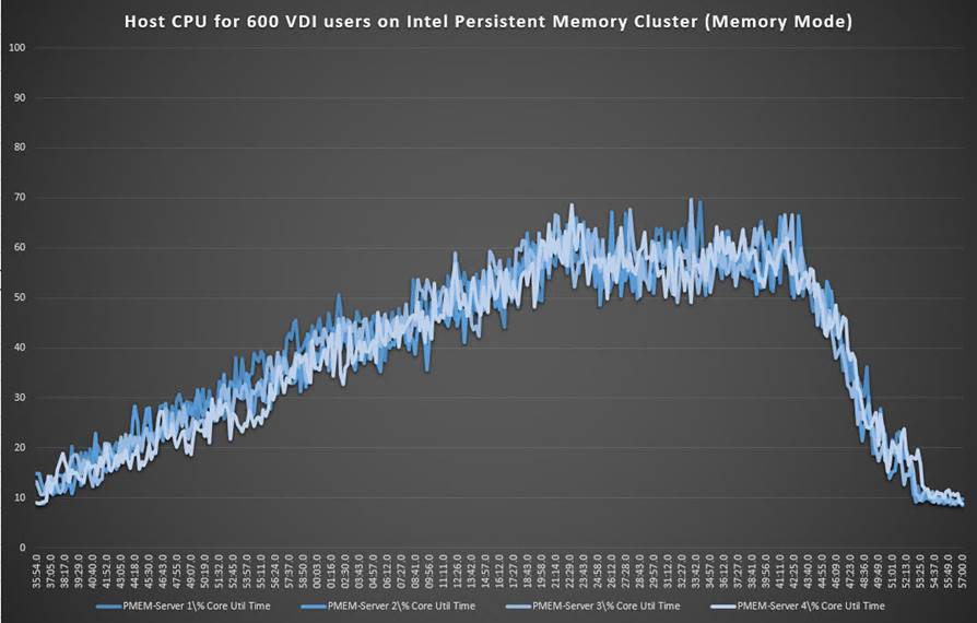
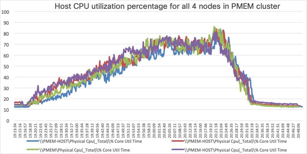
Intel Optane persistent-memory cluster scale testing for Citrix 1912 LTSR VDI: Host CPU utilization
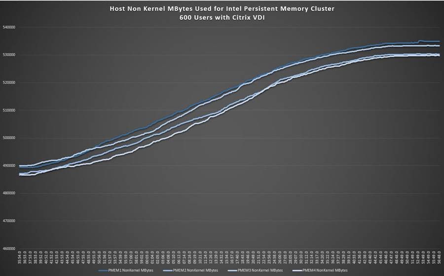
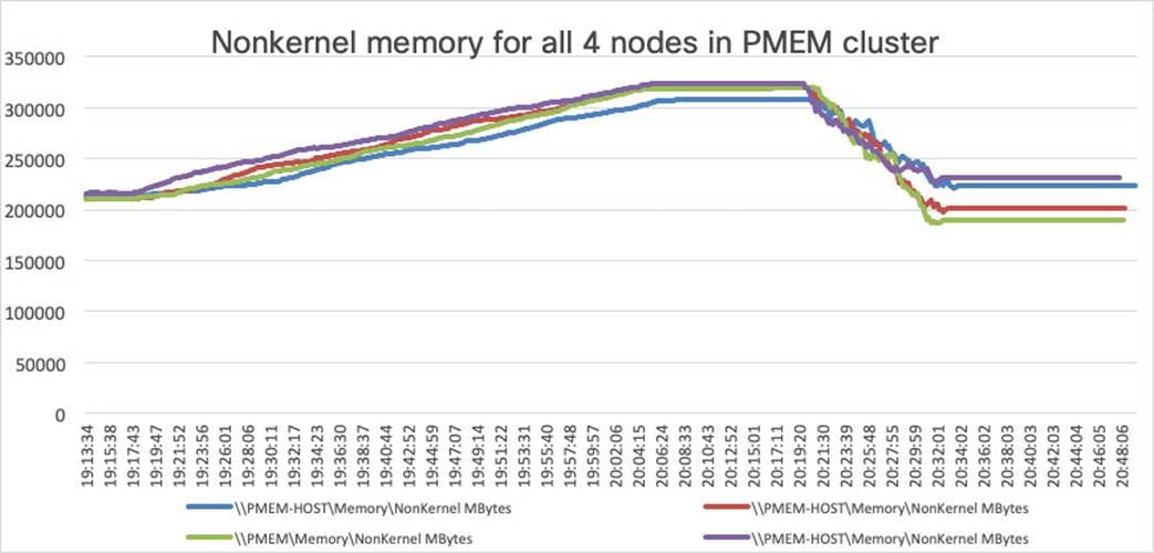
Intel Optane persistent-memory cluster scale testing for Citrix 1912 LTSR VDI: Host memory utilization
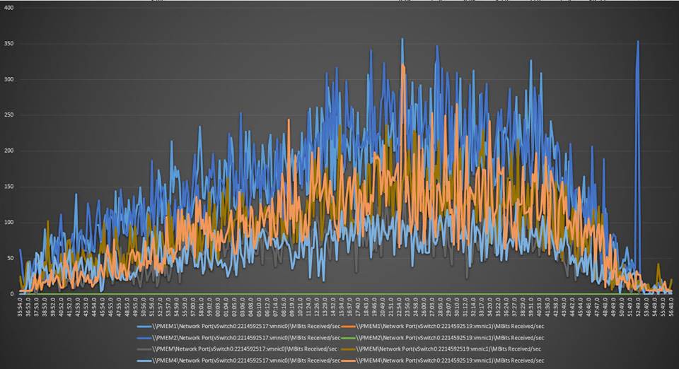
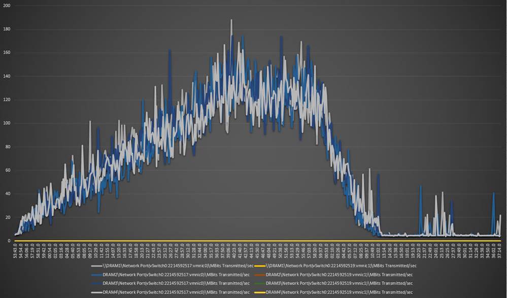
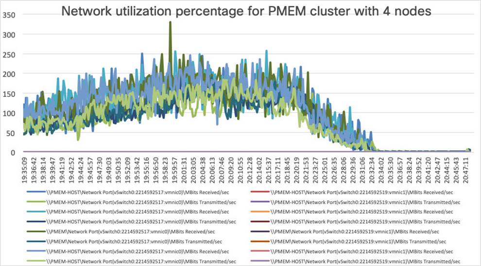
Intel Optane persistent-memory cluster scale testing for Citrix 1912 LTSR VDI: Host network utilization (received traffic)
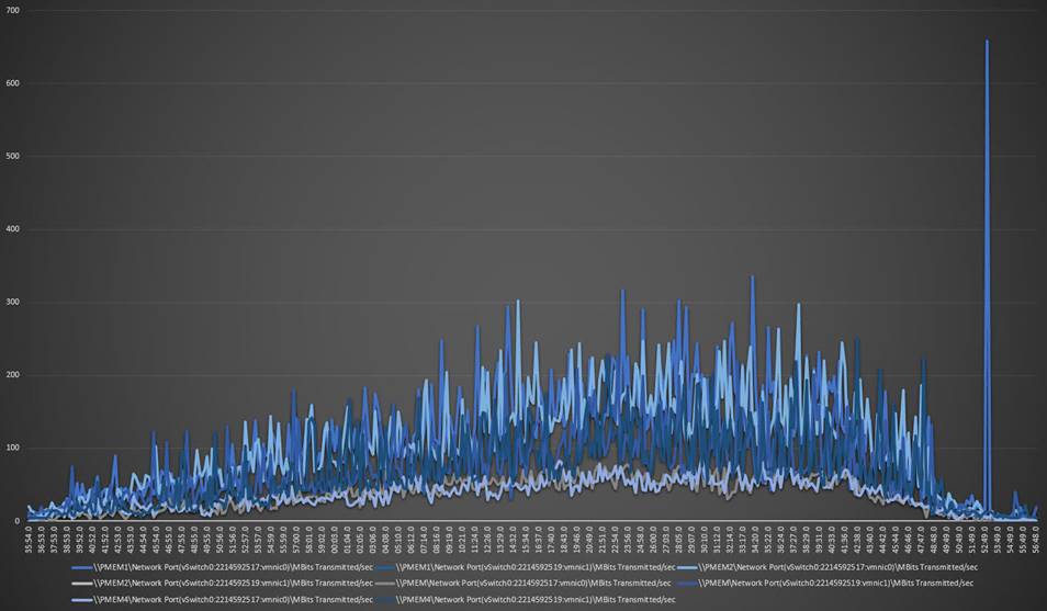
Intel Optane persistent-memory cluster scale testing for Citrix 1912 LTSR VDI: Host network utilization (transmitted traffic)
DRAM cluster test results with VMware Horizon
This section shows the key performance metrics that were captured on the Cisco UCS C240 M5 servers with dual Intel Xeon 5220R processors and 1 TB of 2933-MHz DRAM during cluster testing in the N+1 environment. The cluster testing was performed using Windows 10 64-bit VDI nonpersistent virtual machines (instant clones for VMware Horizon) with two vCPUs and 4 GB of RAM.
Figure 20 shows the Login VSI data.
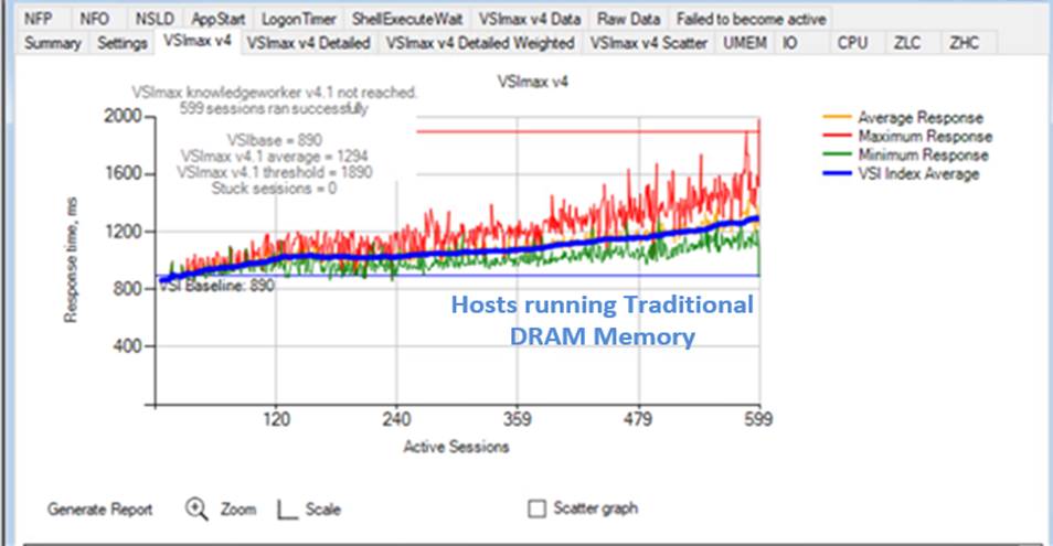
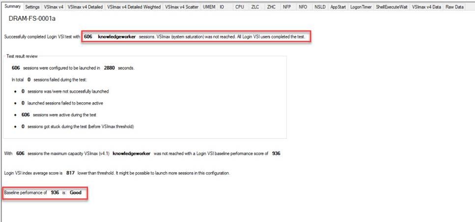
DRAM cluster scale testing for VMware Horizon 8.1 running 600 VDI knowledge worker workload users: Login VSI end-user experience score (in milliseconds [ms])
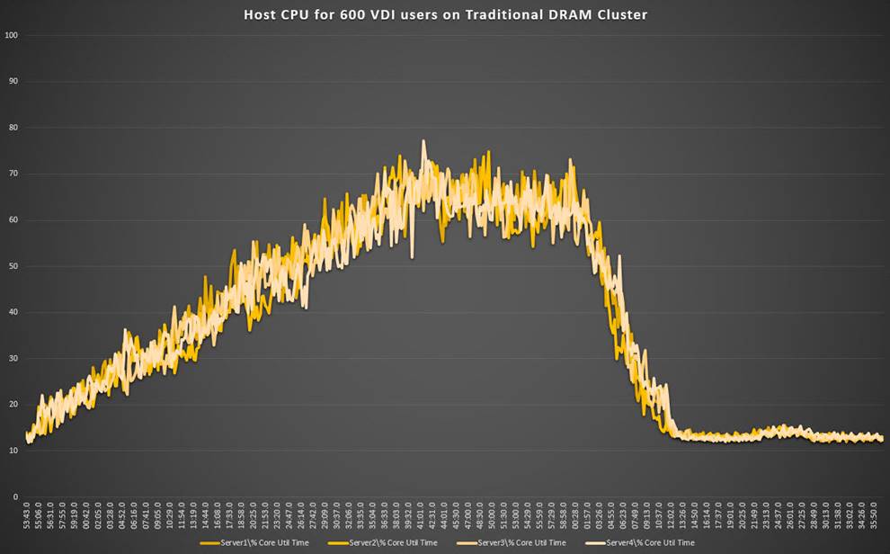
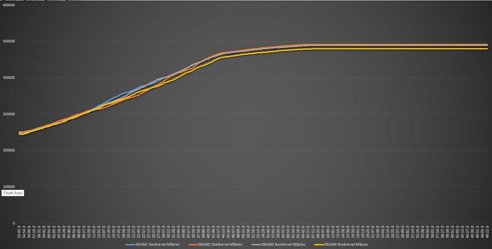
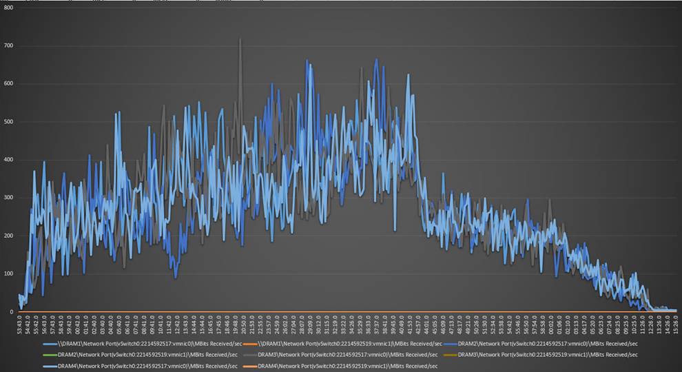
Figure 21, Figure 22, and Figure 23 show performance data for the server running the workload.
DRAM cluster scale testing for VMware Horizon VDI: Host CPU utilization percentage
DRAM cluster scale testing for VMware Horizon VDI: Host memory utilization
DRAM cluster scale testing for VMware Horizon VDI: Host network utilization (received and transmitted traffic)
Intel Optane persistent-memory cluster test results with VMware Horizon
This section shows the key performance metrics that were captured on the Cisco UCS C240 M5 servers with dual Intel Xeon 5220R processors and 1 TB of 2666-MHz PMEM and 384 GB of 2933-MHz DRAM during cluster testing in the N+1 environment. The cluster testing was performed using Windows 10 64-bit VDI nonpersistent virtual machines (instant clones for VMware Horizon and VMware Horizon PVS for VMware Horizon) with two vCPUs and 4 GB of RAM.
Figure 24 shows the Login VSI data.
Intel Optane persistent-memory PMEM cluster scale testing for VMware Horizon 8.1 running 600 VDI knowledge worker workload users: Login VSI end-user experience score (in ms)
Figure 25, Figure 26, and Figure 27 show performance data for the server running the workload.
Intel Optane persistent-memory cluster scale testing for VMware Horizon VDI: Host CPU utilization
Intel Optane persistent-memory cluster scale testing for VMware Horizon VDI: Host memory utilization
Intel Optane persistent-memory cluster scale testing for VMware Horizon VDI: Host network utilization (received)
Test results comparison with Citrix Virtual Apps and Desktops
Figure 28 shows a comparison of CPU utilization using DRAM and PMEM.
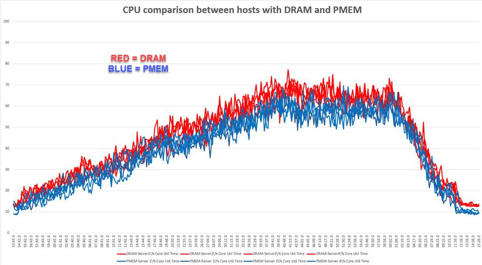
Memory cluster scale testing using Citrix 1912 LTSR VDI: Host CPU utilization
Test results comparison between DRAM and PMEM cluster testing
Figure 29 shows a comparison of CPU utilization percentage using DRAM and PMEM.
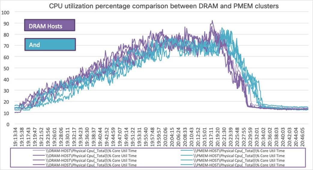
CPU utilization percentage scale testing using| VMware Horizon 8.1 VDI: Host CPU utilization
The introduction of Intel Optane persistent memory in memory mode yields strong performance results similar to those for traditional DRAM-based solutions.
Integrating the Cisco Intersight platform into your environment gives you global visibility into infrastructure health and status along with a constantly growing list of advanced management and support capabilities.
Consult the following references for additional information about the topics discussed in this document.
Products and solutions
● Cisco Intersight platform:
https://www.intersight.com
● Cisco Unified Computing System:
http://www.cisco.com/en/US/products/ps10265/index.html
● Cisco UCS 6454 Fabric Interconnect:
https://www.cisco.com/c/en/us/products/collateral/servers-unified-computing/datasheet-c78-741116.html
● Cisco UCS 5100 Series Blade Server Chassis:
http://www.cisco.com/en/US/products/ps10279/index.html
● Cisco UCS B-Series Blade Servers:
http://www.cisco.com/en/US/partner/products/ps10280/index.html
● Cisco UCS adapters:
http://www.cisco.com/en/US/products/ps10277/prod_module_series_home.html
● Cisco Nexus 9000 Series Switches:
http://www.cisco.com/c/en/us/products/switches/nexus-9000-series-switches/index.html
● Cisco UCS Hardware Compatibility Matrix:
https://ucshcltool.cloudapps.cisco.com/public/
Cisco Validated Designs for VDI
● Deployment guide for FlexPod Datacenter with VMware vSphere 7.0 and NetApp ONTAP 9.7: https://www.cisco.com/c/en/us/td/docs/unified_computing/ucs/UCS_CVDs/flexpod_vmware_vs_7_design.html