Configure Cisco Intersight Managed Mode for FlashStack: Technical Preview Release
Available Languages
Bias-Free Language
The documentation set for this product strives to use bias-free language. For the purposes of this documentation set, bias-free is defined as language that does not imply discrimination based on age, disability, gender, racial identity, ethnic identity, sexual orientation, socioeconomic status, and intersectionality. Exceptions may be present in the documentation due to language that is hardcoded in the user interfaces of the product software, language used based on RFP documentation, or language that is used by a referenced third-party product. Learn more about how Cisco is using Inclusive Language.
The FlashStack™ solution is a validated converged infrastructure jointly developed by Cisco and Pure Storage. The solution is a predesigned, best-practices data center architecture that incorporates computing, storage, and network design best practices to reduce IT risk by validating the architecture and helping ensure compatibility among the components.
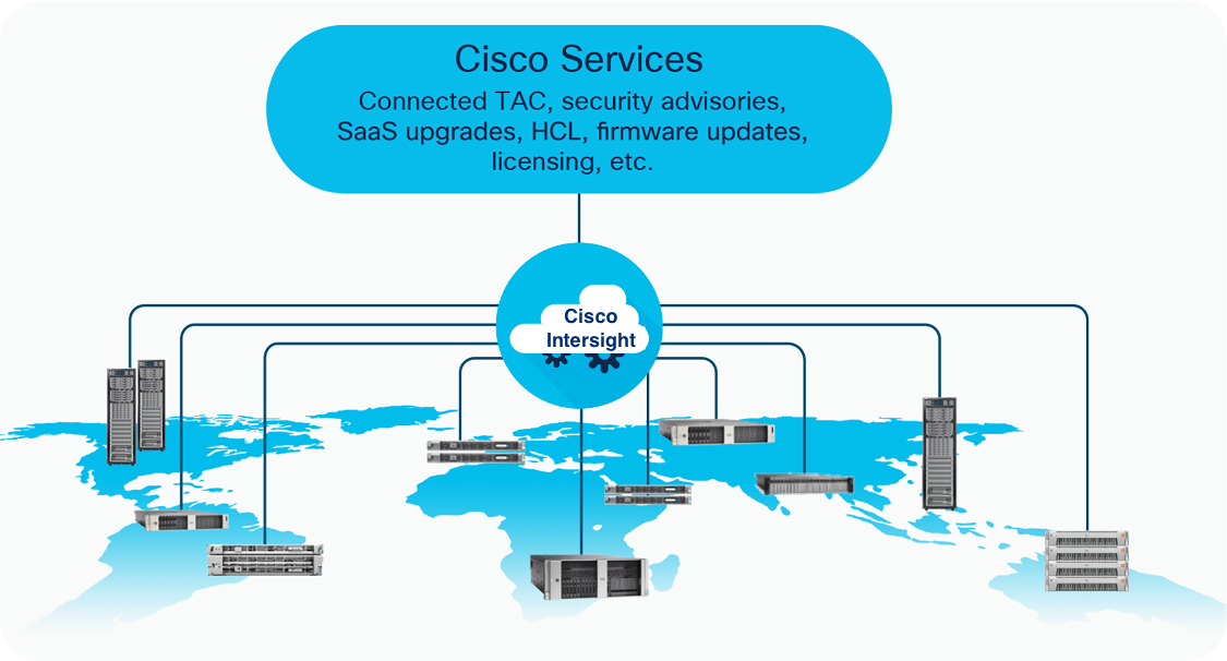
The Cisco Intersight™ platform is a management solution delivered as a service with embedded analytics for Cisco and third-party IT infrastructures. The Cisco Intersight managed mode feature is a new architecture that manages the Cisco Unified Computing System™ (Cisco UCS®) fabric interconnect–attached systems through a Redfish-based standard model. Cisco Intersight managed mode combines the capabilities of Cisco UCS and the cloud-based flexibility of the Cisco Intersight platform, thereby unifying the management experience for both standalone and fabric interconnect–attached systems. Cisco Intersight managed mode standardizes both policy and operation management for the fourth-generation fabric interconnect and Cisco UCS M5 servers. The modular nature of the Cisco Intersight platform provides an easy upgrade path to additional services such as workload optimization and Kubernetes.
This document helps Cisco customers and business partners position and deploy Cisco Intersight managed mode and Cisco UCS within FlashStack environments. The document also presents the new Cisco Intersight managed mode constructs, policies, and workflow involved in deploying Cisco UCS in a FlashStack Virtual Server Infrastructure environment. The Cisco UCS functions previously configured using Cisco UCS Manager can now be delivered through the Cisco Intersight portal, which provides global visibility into the infrastructure health and status along with advanced management and support capabilities.
Although the focus of this document is Cisco UCS and Cisco Intersight managed mode, customers interested in understanding the FlashStack design and deployment details, including configuration of other elements of design and associated best practices, should refer to Cisco® Validated Designs for FlashStack at https://www.cisco.com/c/en/us/solutions/design-zone/data-center-design-guides/data-center-design-guides-all.html#FlashStack.
Note: Cisco Intersight managed mode features are currently in Early Availability supporting scale up to four Cisco UCS chassis and 32 Cisco UCS blade servers. Not all the functions and features in Cisco UCS Manager are supported in the Cisco Intersight managed mode early availability release.
This section provides an overview of the Cisco Intersight and FlashStack platforms.
The Cisco Intersight platform is a software-as-a-service (SaaS) infrastructure lifecycle management platform that delivers simplified configuration, deployment, maintenance, and support. With the Cisco Intersight platform, customers get all the benefits of SaaS delivery and the full lifecycle management of distributed servers connected to Cisco Intersight and third-party storage systems such as Pure Storage across data centers, remote sites, branch offices, and edge environments (Figure 1).
The Cisco Intersight platform is designed to be modular, so customers can adopt services based on their individual requirements. The platform significantly simplifies IT operations by bridging applications with infrastructure, providing visibility and management from bare-metal servers and hypervisors to serverless applications, thereby reducing costs and mitigating risk. This unified SaaS platform uses a unified OpenAPI that natively integrates with the third-party platforms and tools.
Cisco Intersight overview
The main benefits of Cisco Intersight infrastructure services are summarized here:
● Simplify daily operations by automating many daily manual tasks.
● Combine the convenience of a SaaS platform with the capability to connect from anywhere and manage infrastructure through a browser or mobile app.
● Stay ahead of problems and accelerate trouble resolution through advanced support capabilities.
● Gain global visibility of infrastructure health and status along with advanced management and support capabilities.
● Upgrade to add workload optimization and Kubernetes services when needed.
Cisco Intersight Virtual Appliance and Private Virtual Appliance
In addition to the SaaS deployment model running on Intersight.com, on-premises options can be purchased separately. The Cisco Intersight Virtual Appliance and Cisco Intersight Private Virtual Appliance are available for organizations that have additional data locality or security requirements for managing systems. The Cisco Intersight Virtual Appliance delivers the management features of the Cisco Intersight platform in an easy-to-deploy VMware or Microsoft Hyper-V Server virtual machine that allows you to control the system details that leave your premises. The Cisco Intersight Private Virtual Appliance is provided in a form factor specifically designed for users who operate in disconnected (air gap) environments. The Private Virtual Appliance requires no connection to public networks or back to Cisco to operate. At this time, Cisco Intersight managed mode is a tech-preview feature, and the configuration is available only through the Cisco Intersight SaaS platform.
Cisco Intersight device connector for Pure Storage
Cisco Intersight can integrate with the third-party infrastructure components such as hypervisors and storage arrays using Cisco Intersight Assist virtual machine and device connectors. The Cisco Intersight Assist feature helps you add endpoint devices to Cisco Intersight. A data center may have multiple devices that do not connect directly with Cisco Intersight. Any device that is supported by Cisco Intersight but does not connect directly with it needs a connection mechanism. Cisco Intersight Assist provides that connection mechanism and helps you add devices to Cisco Intersight. The Cisco Intersight Assist virtual machine is available in the Cisco Intersight Virtual Appliance, which is distributed as a deployable virtual machine in an Open Virtual Appliance (OVA) file format.
The device connector provides a secure way for connected targets to send information and receive control instructions from the Cisco Intersight portal using a secure Internet connection. Cisco and Pure Storage engineering teams have worked together to develop a device connector to integrate Pure Storage FlashArray with Cisco Intersight. This integration provides the following the capabilities for managing the Pure Storage FlashArray through the Cisco Intersight portal:
● View general inventory information such as storage device inventory (including FlashArray hardware), capacity, use, and configuration information (volumes, host groups, drives, ports, etc.).
● Add certain storage device information widgets (capacity, utilization, etc.) to the Cisco Intersight dashboard (Figure 2).
● Automate Pure Storage provisioning of volumes using the Cisco Intersight workflow designer.
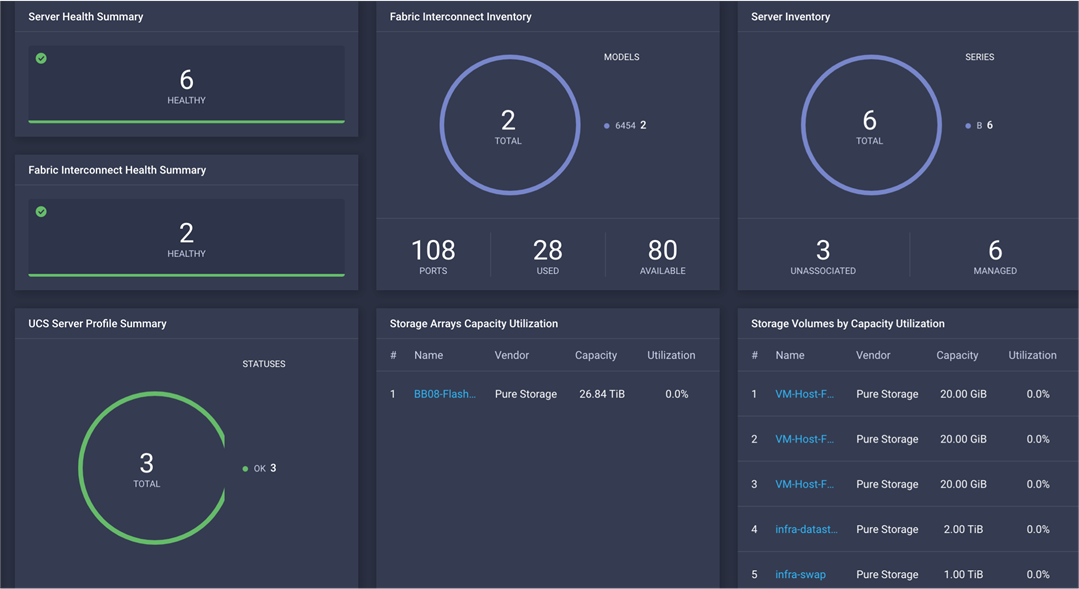
Pure Storage FlashArray widgets in Cisco Intersight dashboard
Note: Integration of Pure Storage FlashArray requires the Cisco Intersight Advantage license. Storage automation requires the Cisco Intersight Premier license.
FlashStack Virtual Server Infrastructure overview
Many enterprises today are seeking pre-engineered solutions that standardize data center infrastructure, offering organizations operational efficiency, agility, and scale to address cloud and bimodal IT and their business. Their challenge is complexity, diverse application support, efficiency and risk. FlashStack (Figure 3) addresses all of these challenges with these features:
● Stateless architecture, providing the capability to expand and adapt to new business requirements
● Reduced complexity, automatable infrastructure, and easily deployed resources
● Robust components capable of supporting high-performance and high-bandwidth virtualized applications
● Efficiency through optimization of network bandwidth and in-line storage compression with deduplication
● Risk reduction at each level of the design with resiliency built into each touch point
Cisco and Pure Storage have partnered to deliver a number of Cisco Validated Designs, which use best-in-class storage, server, and network components to serve as the foundation for virtualized workloads, enabling efficient architectural designs that can be deployed quickly and confidently.
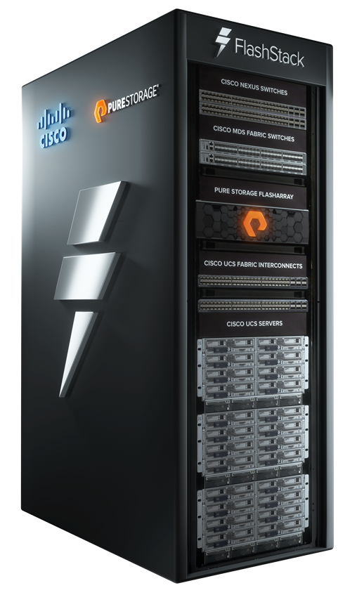
FlashStack
FlashStack Virtual Server Infrastructure includes the following core components (Figure 4):
● Cisco UCS platform
● Cisco Nexus® Family switches
● Cisco MDS 9000 Family switches
● Pure Storage FlashArray
FlashStack Virtual Server Infrastructure components
All the FlashStack components have been integrated so that customers can deploy the solution quickly and economically without many of the risks associated with researching, designing, building, and deploying similar solutions from the foundation up. One of the main benefits of FlashStack is its ability to maintain consistency at scale. Each of the component families shown in Figure 4. (Cisco UCS, Cisco Nexus, Cisco MDS 9000, and Pure Storage FlashArray systems) offers platform and resource options to scale the infrastructure up or down, while supporting the same features and functions that are required under the configuration and connectivity best practices of FlashStack.
This section discusses the infrastructure setup, software and hardware requirements, and some of the design details of the Cisco Intersight managed mode deployment model. Cisco Intersight managed mode is a new feature and specific hardware and software requirements must be followed to configure Cisco UCS using Cisco Intersight managed mode. The selection of FlashStack infrastructure components presented here closely aligns with Cisco Intersight managed mode requirements. This section does not cover the design details of FlashStack components such as Cisco Nexus and Cisco MDS switches and Pure Storage FlashArray systems because their design and configuration conform to various Cisco Validated Designs for FlashStack and are covered widely elsewhere. This document focuses on the design elements of the new Cisco Intersight managed mode configuration.
During initial fabric interconnect setup for a fabric-attached Cisco UCS deployment, customers can choose to deploy fabric interconnects and Cisco UCS in the native Cisco UCS Manager managed mode or the new Cisco Intersight managed mode. This document discusses Cisco UCS deployment in Cisco Intersight managed mode, and all the configuration steps are performed using the Cisco Intersight SaaS platform.
Note: This document does not cover the migration of policies from a Cisco UCS Manager managed system to a Cisco Intersight managed mode system. The configuration parameters and procedures for the two configuration modes are quite different and require manual translation of policies when you move from one mode to the other.
Before setting up Cisco Intersight managed mode, please review the supported hardware, software and licensing requirements that follow.
Cisco Intersight managed mode supported hardware
The hardware listed in Table 1 is required to deploy Cisco UCS using Cisco Intersight managed mode.
Table 1. Cisco Intersight managed mode supported hardware
| Component |
Model number |
| Fabric interconnect |
Fourth-generation fabric interconnect: UCS-FI-6454 |
| Cisco UCS B-Series Blade Servers |
Cisco UCS B-Series M5: UCSB-B200-M5 and UCSB-B480-M5 |
| Cisco UCS C-Series Rack Servers |
Cisco UCS C-Series M5:UCSC-C220-M5,UCSC-C240-M5, UCSC-C480-M5, UCSC-C480-M5ML, and Cisco UCS C240 SD M5 |
| Chassis |
N20-C6508 and UCSB-5108-AC2 |
| I/O module (IOM) |
UCS-IOM-2204XP, UCS-IOM-2208XP, and UCS-IOM-2408 |
| Cisco UCS B-Series adapters |
UCSB-MLOM-40G-04 and UCSB-VIC-M84-4P |
| Cisco UCS C-Series adapters |
UCSC-MLOM-C25Q-04 and UCSC-PCIE-C25Q-04 |
| Validated software |
Release 4.1(2a)* |
*Make sure that all the Cisco UCS components, including servers and adapters, have been upgraded to the correct version. Device discovery will fail if an unsupported version is installed on the Cisco UCS components. The items highlighted in bold were used during the validation process discussed in this document. Cisco UCS software release 4.1(3b) or later is recommended for all the Intersight managed mode deployments.
For the most up-to-date support information for Cisco Intersight managed mode, see https://intersight.com/help/supported_systems#supported_hardware_systems_and_software_versions.
Cisco Intersight uses a subscription-based license with multiple tiers. You can purchase a subscription duration of one, three, or five years and choose the required Cisco UCS server volume tier for the selected subscription duration. Each Cisco endpoint automatically includes a Cisco Intersight Base license at no additional cost when you access the Cisco Intersight portal and claim a device. You can purchase any of the following higher-tier Cisco Intersight licenses using the Cisco ordering tool:
● Cisco Intersight Essentials: Essentials includes all functions of the Base license plus additional features including Cisco UCS Central Software and Cisco Integrated Management Controller (IMC) supervisor entitlement, policy-based configuration with server profiles, firmware management, and evaluation of compatibility with the Cisco Hardware Compatibility List (HCL).
● Cisco Intersight Advantage: Advantage offers all features and functions of the Base and Essentials tiers. It also includes storage widgets, storage inventory, storage capacity, and storage utilization, starting with support for Pure Storage and cross-domain inventory correlation across physical computing, physical storage, and virtual environments (VMware ESXi). It also includes OS installation for supported Cisco UCS platforms.
● Cisco Intersight Premier: In addition to the functions provided in the Advantage tier, Cisco Intersight Premier includes full subscription entitlement for Cisco UCS Director, providing orchestration across Cisco UCS and third-party systems, including virtual machines (VMware vCenter) and physical storage (Pure Storage).
Server deployment in Cisco Intersight managed mode requires at least an Essentials license. The validation testing for this document used a Premier license to showcase Pure Storage integration with Intersight. However, all the Cisco UCS functions covered in this document (see the appendix) are supported with the Essentials license. For more details about the features provided in the various licensing tiers, visit https://intersight.com/help/getting_started#licensing_requirements.
View the current Cisco Intersight Infrastructure Service licensing.
FlashStack setup for Cisco Intersight managed mode configuration
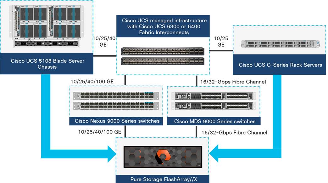
The FlashStack setup used to validate Cisco Intersight managed mode configuration aligns with the Fibre Channel design presented in the FlashStack for VMware vSphere design: https://www.cisco.com/c/en/us/td/docs/unified_computing/ucs/UCS_CVDs/flashstack_vsi_vmware_vsphere_70_design.html. Figure 5 shows the connectivity between the various elements of FlashStack.
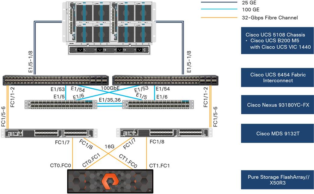
Topology used to verify Cisco Intersight managed mode configuration in a FlashStack environment
In the FlashStack environment, these components are set up as follows:
● Cisco UCS 6454 Fabric Interconnects provide the chassis and network connectivity.
● The Cisco UCS 5108 Blade Server Chassis connects to fabric interconnects using Cisco UCS 2408 IOMs, with four 25 Gigabit Ethernet ports used on each IOM to connect to the fabric interconnect.
● Cisco UCS B200 M5 servers contain fourth-generation Cisco virtual interface cards (VICs): UCSB-MLOM-40G-04.
● Cisco Nexus 93180YC-FX Switches running in Cisco NX-OS mode provide the switching fabric.
● Cisco UCS 6454 Fabric Interconnect 100 Gigabit Ethernet uplink ports connect to Cisco Nexus 93180YC-FX Switches in a virtual port channel (vPC).
● Cisco UCS 6454 Fabric Interconnects are connected to the Cisco MDS 9132T switches using 32-Gbps Fibre Channel connections configured as a port channel for SAN connectivity.
● Pure Storage FlashArray//X50 R3 connects to the Cisco MDS 9132T 32-Gbps 32-Port Fibre Channel Switches using 16-Gbps Fibre Channel connections for SAN connectivity.
● VMware 7.0 ESXi software is installed on Cisco UCS B200 M5 servers to validate the infrastructure.
Note: At this time, Pure storage controller connection to Cisco UCS fabric interconnects using Fibre Channel links, also known as direct-attached SAN connectivity, is not supported.
Configuration constructs for Cisco Intersight managed mode
Cisco Intersight managed mode unites the capabilities of the Cisco UCS platform and the cloud-based flexibility of the Cisco Intersight platform, thus unifying the management experience for standalone and fabric interconnect–attached systems. Cisco Intersight managed mode standardizes policy and operation management for fourth-generation fabric interconnects and Cisco UCS M5 servers.
At a high level, configuring Cisco UCS using Intersight managed mode consists of the steps shown in Figure 6. Details of these steps are covered in the following sections.
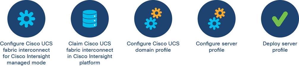
Steps to configure Cisco UCS using Cisco Intersight managed mode
Configuring Cisco UCS fabric interconnects for Cisco Intersight managed mode
The initial configuration for a fabric interconnect can be performed using the serial console when the fabric interconnect boots for the first time. This can happen either during factory installation or after the existing configuration has been erased. During the initial configuration, for the management mode the configuration wizard enables customers to choose whether they want to manage the fabric interconnect through Cisco UCS Manager or the Cisco Intersight platform. Customers can switch the management mode for the fabric interconnects between Cisco Intersight and Cisco UCS Manager at any time. However, this is a disruptive process because it causes all endpoint configurations to be reset and results in the loss of the current configuration. In the validation process described here, the existing configuration on the Cisco UCS fabric interconnects was cleared, and the system was set up for Cisco Intersight managed mode.
0shows the output from the fabric interconnect console to enable Cisco Intersight managed mode.
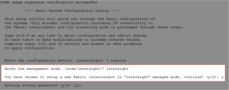
Fabric interconnect setup for Cisco Intersight managed mode
Claiming Cisco UCS fabric interconnects in Cisco Intersight
After you set up the Cisco UCS fabric interconnect for Cisco Intersight managed mode, you can add the fabric interconnects to a new or an existing Cisco Intersight account (Figure 8. ). The details of the device claim process are covered in the appendix. When a Cisco UCS fabric interconnect is successfully added to the Cisco Intersight platform, all future configuration steps are completed in the Cisco Intersight portal.
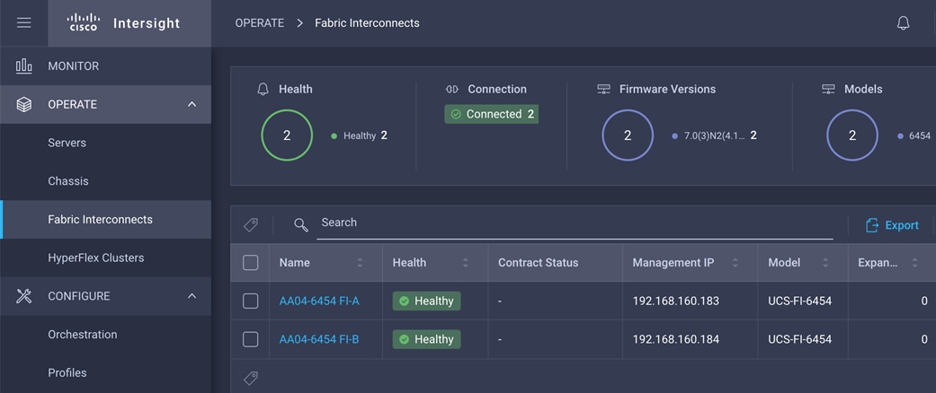
Cisco Intersight platform: Adding fabric interconnects
You can verify whether a Cisco UCS fabric interconnect is in Cisco UCS Manager managed mode or Cisco Intersight managed mode by clicking the fabric interconnect name and looking at the detailed information screen for the fabric interconnect, as shown in 0
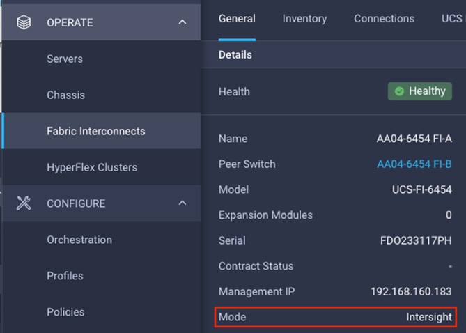
Fabric interconnect in Cisco Intersight managed mode
Configuring the Cisco UCS domain profile
A Cisco UCS domain profile configures a fabric interconnect pair through reusable policies, allows configuration of the ports and port channels, and configures the VLANs and VSANs to be used in the network. It defines the characteristics of and configures the ports on the fabric interconnects. The domain-related policies can be attached to the profile either at the time of creation or later. One Cisco UCS domain profile can be assigned to one fabric interconnect domain, and the Cisco Intersight platform supports the attachment of one port policy per Cisco UCS domain profile. Policies that are attached to a Cisco UCS domain profile can be created either before or during the creation of the profile.
Some of the characteristics of the Cisco UCS domain profile set up for this validation are as follows:
● A single domain profile is created for the pair of Cisco UCS fabric interconnects.
● Separate port policies are defined for the two fabric interconnects because each fabric interconnect uses unique Fibre Channel and VSAN configurations. If boot from SAN were not required, the same port policy could have been reused across the two fabric interconnects.
● The VLAN configuration policy is common to the fabric interconnect pair because both fabric interconnects are configured for the same set of VLANs.
● The VSAN configuration policies are unique for the two fabric interconnects because the VSANs are unique.
● The Network Time Protocol (NTP), network connectivity, and system quality-of-service (QoS) policies are common to the fabric interconnect pair.
After the Cisco UCS domain profile has been successfully created, the fabric interconnects in the FlashStack environment can do the following:
● Form an Ethernet port channel with the Cisco Nexus switch.
● Form a Fibre Channel port channel with the Cisco MDS switch.
● Discover the Cisco UCS chassis and the blades.
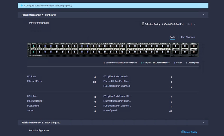
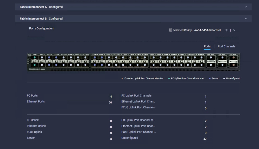
Figure 10 shows a summary of the Cisco UCS fabric interconnect and the port configuration after the Cisco UCS domain profile was deployed.
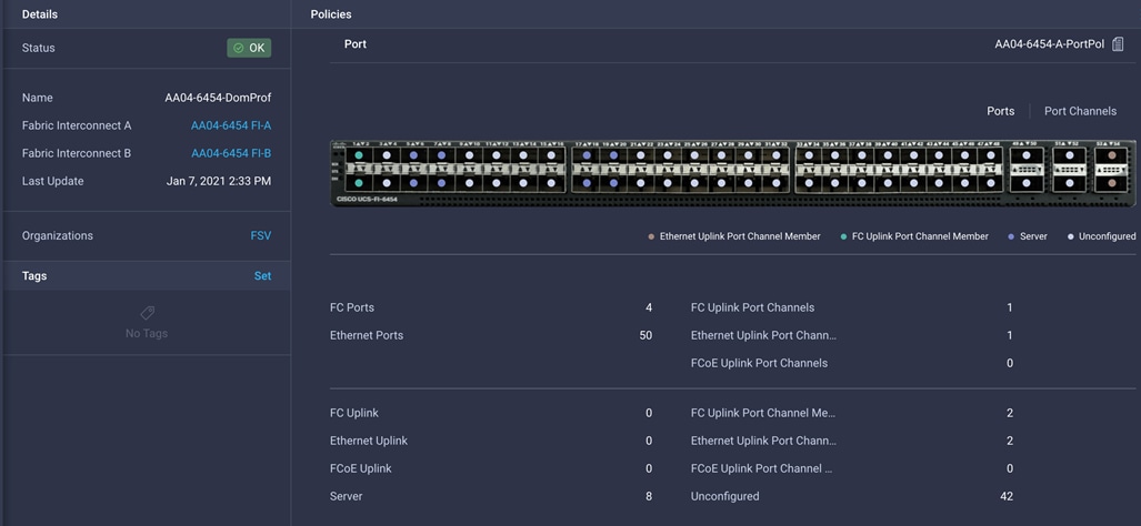
Cisco UCS domain profile
Creating and deploying a server profile
A server profile enables resource management by simplifying policy alignment and server configuration. You can create server profiles using the server profile wizard to provision servers, create policies to help ensure smooth deployment of servers, and eliminate failures caused by inconsistent configurations. The server profile wizard groups the server policies into the following four categories to provide a quick summary view of the policies that are attached to a profile:
● Computing policies: BIOS, boot order, and virtual media policies
● Network policies: Adapter configuration, LAN connectivity, and SAN connectivity policies
◦ The LAN connectivity policy requires you to create Ethernet network policy, Ethernet adapter policy, and Ethernet QoS policy.
◦ The SAN connectivity policy requires you to create Fibre Channel network policy, Fibre Channel adapter policy, and Fibre Channel QoS policy.
● Storage policies: Secure Digital (SD) card and storage policies (not used in FlashStack)
● Management policies: Device connector; Intelligent Platform Management Interface (IPMI) over LAN; Lightweight Directory Access Protocol (LDAP); local user; network connectivity; Simple Mail Transfer Protocol (SMTP); Simple Network Management Protocol (SNMP); Secure Shell (SSH); Serial over LAN (SOL); syslog; and virtual keyboard, video, and mouse (KVM) policies
Some of the characteristics of the server profile set up for this validation are as follows:
● BIOS policy is created to specify various server parameters in accordance with FlashStack best practices.
● Boot-order policy defines virtual media (KVM Mapper DVD) and all four SAN paths for Pure Storage Fibre Channel interfaces.
● IMC access policy defines the management IP address pool for KVM access.
● Local user policy is used to provide KVM access.
● LAN connectivity policy is used to create four virtual network interface cards (vNICs)—two for management virtual switches (vSwitches) and two for application virtual dedicated servers (VDSs)—along with various policies and pools.
● SAN connectivity policy is used to create two virtual host bus adapters (vHBAs)—one for SAN A and one for SAN B—along with various policies and pools.
Figure 11 shows various policies associated with the server profile, and Figure 12. shows a successfully deployed server profile and associated blade.
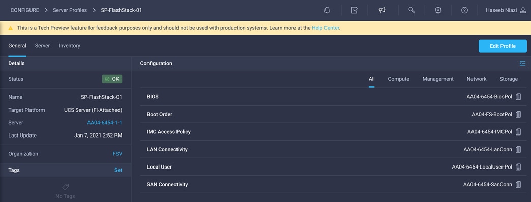
Server profile policies
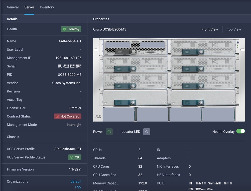
Server profile details
After a server profile has been successfully deployed, the server successfully boots from SAN storage hosted on the Pure storage. Additional server profiles are created simply by cloning the first server profile and programming the Cisco MDS switches and Pure storage controllers for various SAN parameters. For step-by-step deployment guidance for Cisco UCS and Cisco Intersight managed mode, refer to the appendix.
Integrating Pure Storage FlashArray with Cisco Intersight
Cisco Intersight works with certain third-party infrastructure, including Pure Storage’s FlashArray and VMware vCenter, using third-party device connectors. Device connectors built in to Cisco UCS software are used to establish the connection between the computing infrastructure and Cisco Intersight. However, third-party infrastructure does not contain any built-in device connectors. The Cisco Intersight Assist appliance bridges this gap to enable Cisco Intersight to communicate with Pure Storage FlashArray (and VMware vCenter).
Note: To integrate and view various Pure Storage FlashArray parameters from Cisco Intersight, you must have a Cisco Intersight Advantage license. To use Cisco Intersight orchestration and workflows to provision the FlashArray, you need a Intersight Premier license.
To integrate Pure Storage FlashArray with Cisco Intersight, a Cisco Intersight Assist virtual machine was deployed in the FlashStack infrastructure and claimed as a target in Cisco Intersight (Figure 13). For information about how to install a Cisco Intersight Assist virtual machine, refer to https://www.cisco.com/c/en/us/td/docs/unified_computing/Intersight/cisco-intersight-assist-getting-started-guide/m-installing-cisco-intersight-assist.html. Using this Cisco Intersight Assist virtual machine, Pure Storage FlashArray was claimed as a target in Cisco Intersight (Figure 14).
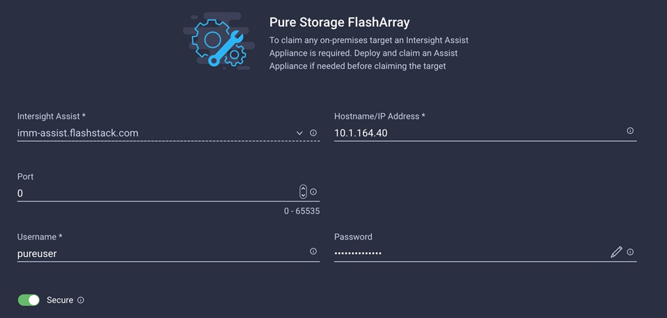
Adding Pure Storage FlashArray as a target using Cisco Intersight Assist
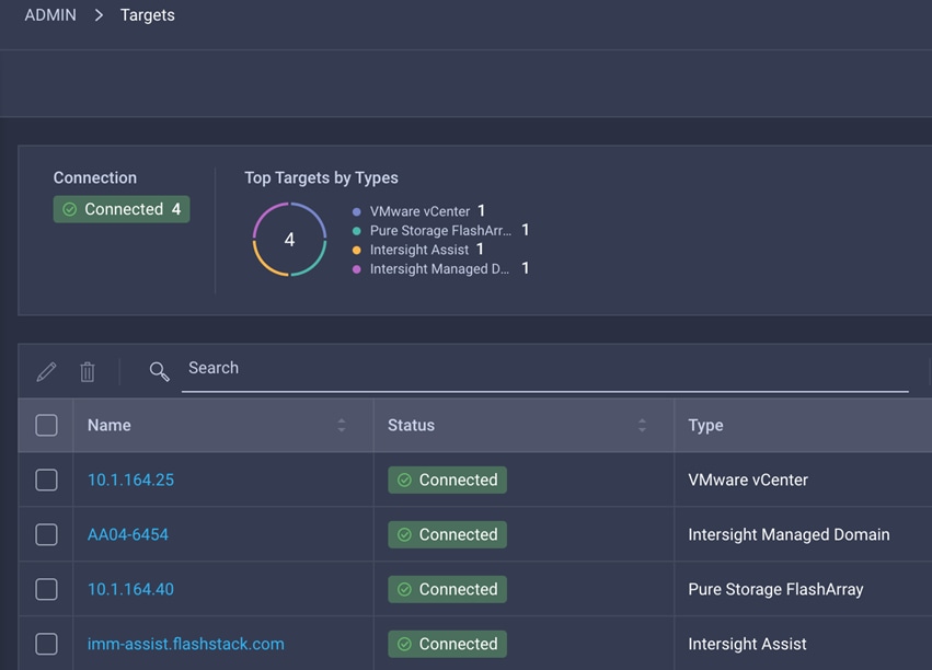
Various targets in Cisco Intersight
After successfully adding the FlashArray, you can view storage-level information in Cisco Intersight (Figure 15).
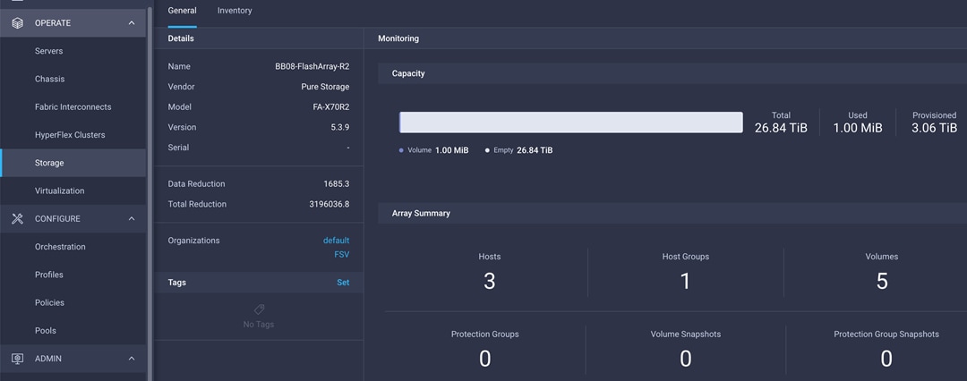
Pure Storage FlashArray information in Cisco Intersight
Table 2 lists some of the main storage properties presented in Cisco Intersight.
Table 2. Pure Storage FlashArray information in Cisco Intersight
| Category |
Name |
Details |
| General |
Name |
Name of the FlashArray |
| Vendor |
Pure Storage |
|
| Model |
FlashArray model information (for example, FA-X70R2) |
|
| Version |
Software version (for example, 5.3.9) |
|
| Serial |
Serial number of the FlashArray |
|
| Data Reduction |
Storage efficiency |
|
| Total Reduction |
Storage efficiency |
|
| Monitoring |
Capacity |
Total, used, and provisioned system capacity |
| Array Summary |
Summary of hosts, host groups, volumes, etc. in the system |
|
| Inventory |
Hosts |
Hosts defined in the system and associated ports, volumes, and protection group information |
| Host Groups |
Host groups defined in the system and associated hosts, volumes, and protection groups in the system |
|
| Volumes |
Configured volumes and volume-specific information such as capacity, data reduction, etc. |
|
| Protection Groups |
Protection groups defined in the system and associated targets, members, etc. |
|
| Controllers |
FlashArray controllers and their state, version, and model information |
|
| Drives |
Storage drive–related information, including type and capacity information |
|
| Ports |
Information related to physical ports, including World Wide Port Name (WWPN) and iSCSI Qualified Name (IQN) information |
You can also add the storage dashboard widgets to Cisco Intersight for viewing FlashArray information at a glance on the Cisco Intersight dashboard (Figure 16).
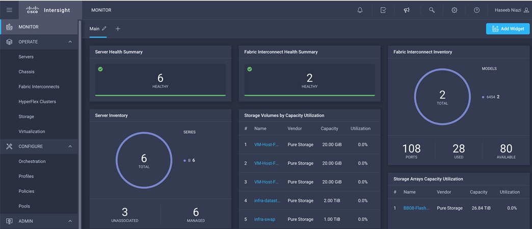
Pure Storage FlashArray widgets in Cisco Intersight
These storage widgets provide useful information at a glance, such as the following:
● Storage arrays and capacity utilization
● Top-five storage volumes by capacity utilization
● Storage versions summary, providing information about the software version and the number of storage systems running that version
The Cisco Intersight orchestrator provides various workflows specific to Pure Storage FlashArray that can be used to automate storage provisioning. The storage workflows available for Pure Storage FlashArray are listed in Table 3.
Table 3. Pure Storage workflows in Cisco Intersight orchestrator
| Name |
Details |
| New Storage Host |
Create a new storage host. If a host group is provided as input, then the host will be added to the host group. |
| New Storage Host Group |
Create a new storage host group. If hosts are provided as inputs, the workflow will add the hosts to the host group. |
| New VMFS Datastore |
Create a storage volume and build a Virtual Machine File System (VMFS) data store on the volume. |
| Remove Storage Host |
Remove a storage host. If a host group name is provided as input, the workflow will also remove the host from the host group. |
| Remove Storage Host Group |
Remove a storage host group. If hosts are provided as input, the workflow will remove the hosts from the host group. |
| Remove VMFS datastore |
Remove a VMFS data store and remove the backing volume from the storage device. |
| Update Storage Host |
Update the storage host details. If the inputs for a task are provided, then the task is run; otherwise, it is skipped. |
| Update VMFS Datastore |
Expand a data store on the hypervisor manager by extending the backing storage volume to specified capacity, and then expand the data store to use the additional capacity. |
Integrating the Cisco Intersight platform into a FlashStack environment provides global visibility of infrastructure health and status along with advanced management and support capabilities. The Cisco Intersight platform delivers a convenient SaaS solution with the capability to connect from anywhere and manage infrastructure through a browser or mobile app while allowing customers to stay ahead of problems and accelerate trouble resolution through advanced support capabilities.
Consult the following references for additional information about the topics discussed in this document.
Products and solutions
● Cisco Intersight:
https://www.intersight.com
● Cisco Intersight managed mode: https://www.cisco.com/c/en/us/td/docs/unified_computing/Intersight/b_Intersight_Managed_Mode_Configuration_Guide.html
● Cisco Unified Computing System:
http://www.cisco.com/en/US/products/ps10265/index.html
● Cisco UCS 6454 Fabric Interconnect: https://www.cisco.com/c/en/us/products/collateral/servers-unified-computing/datasheet-c78-741116.html
● Cisco UCS 5100 Series Blade Server Chassis:
http://www.cisco.com/en/US/products/ps10279/index.html
● Cisco UCS B-Series Blade Servers:
http://www.cisco.com/en/US/partner/products/ps10280/index.html
● Cisco UCS adapters:
http://www.cisco.com/en/US/products/ps10277/prod_module_series_home.html
● Cisco Nexus 9000 Series Switches:
http://www.cisco.com/c/en/us/products/switches/nexus-9000-series-switches/index.html
● Pure Storage FlashArray//X:
https://www.purestorage.com/products/flasharray-x.html
● Cisco UCS Hardware Compatibility Matrix:
https://ucshcltool.cloudapps.cisco.com/public/
● Pure FlashStack Compatibility Matrix:
https://support.purestorage.com/FlashStack/Product_Information/FlashStack_Compatibility_Matrix
https://support.purestorage.com/FlashArray/Getting_Started/Compatibility_Matrix
● FlashStack Datacenter Design Guide
https://www.cisco.com/c/en/us/solutions/design-zone/data-center-design-guides/data-center-design-guides-all.html#FlashStack
Appendix: Configuration details
This appendix describes how to set up a Cisco UCS fabric in Cisco Intersight managed mode and specify the FlashStack-related computing configuration using the Cisco Intersight platform. This appendix does not discuss how to set up the switching infrastructure or the storage. Refer to the relevant FlashStack deployment guides for details about these components: https://www.cisco.com/c/en/us/td/docs/unified_computing/ucs/UCS_CVDs/flashstack_vsi_fc_vmware_vsphere_70.html.
Configure Cisco Intersight managed mode on Cisco UCS fabric interconnects
The Cisco UCS fabric interconnects need to be set up to support Cisco Intersight managed mode. If you are converting an existing pair of Cisco UCS fabric interconnects, first erase the configuration and reboot your system. Converting fabric interconnects to Cisco Intersight managed mode is a disruptive process, and configuration information will be lost. Customers are encouraged to make a backup of their existing configuration if they plan only to test Cisco Intersight managed mode and then revert to Cisco UCS Manager managed mode.
1. Erase the configuration on existing fabric interconnects. Connect to each of the fabric interconnect consoles, log in as admin, and enter the following commands:
Note: This erasure process is not needed on brand-new fabric interconnects that have not been configured yet.
UCS-A# connect local-mgmt
UCS-A(local-mgmt)# erase configuration
All UCS configurations will be erased and system will reboot. Are you sure? (yes/no): yes
2. Configure Fabric Interconnect A (FI-A). On the Basic System Configuration Dialog screen, set the management mode to Intersight. All the remaining settings are similar to those for the Cisco UCS Manager managed mode (UCSM-Managed). Note that there is no virtual IP address setting anymore when Cisco Intersight managed mode is selected.
After applying the settings, make sure you can ping the fabric interconnect management IP address. When Fabric Interconnect A is correctly set up and is available, Fabric Interconnect B will automatically discover Fabric Interconnect A during its setup process as shown in the next step.
3. Configure Fabric Interconnect B (FI-B). For the configuration method, choose console. Fabric Interconnect B will detect the presence of Fabric Interconnect A and will prompt you to enter the admin password for Fabric Interconnect A. Provide the management IP address for Fabric Interconnect B and apply the configuration.
Set up Cisco Intersight account
In this step, using the unique device information for the Cisco UCS, you set up a new Cisco Intersight account. Customers also can choose to add the Cisco UCS devices set up for Cisco Intersight managed mode to an existing Cisco Intersight account; however, that procedure is not covered in this document.
After completing the initial configuration for the fabric interconnects, log in to Fabric Interconnect A using your web browser to capture the Cisco Intersight connectivity information.
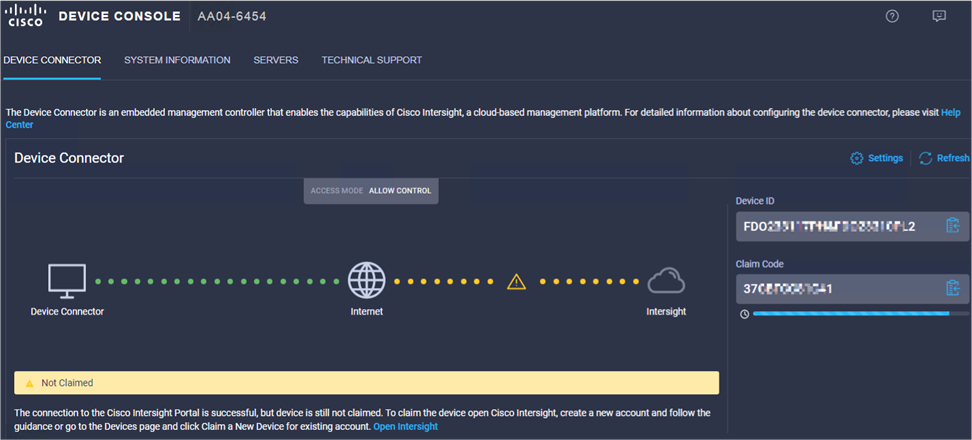
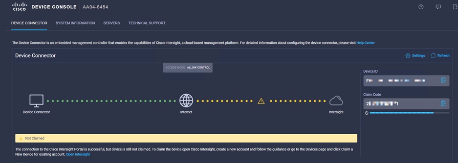
1. Use the management IP address of Fabric Interconnect A to access the device from a web browser and the previously configured admin password to log in to the device.
2. Under Device Connector, you should see the current device status as ”Not claimed.” Note, or copy, the Device ID and Claim Code information to use to set up a new Cisco Intersight account.
Note: The Device ID and Claim Code information can also be used to claim the Cisco UCS devices set up with Cisco Intersight managed mode in an existing Cisco Intersight account.
Create a new Cisco Intersight account
Next, create a new Cisco Intersight account.
1. Visit https://www.intersight.com and click “Don't have an Intersight Account? Create an account.”
2. Provide an account name and the device information captured in the preceding steps to create the account. This step will automatically add the Cisco UCS device to the new Cisco Intersight account.

3. After the account has been created successfully, click Go To Intersight.

4. You should see a screen with your Cisco Intersight account.
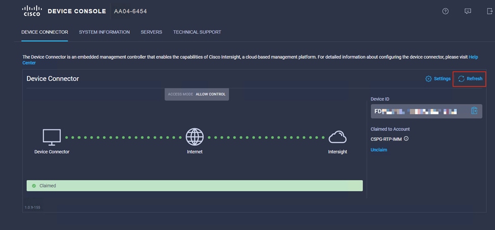
Verify addition of Cisco UCS fabric interconnects to Cisco Intersight
Now verify that Cisco UCS fabric interconnects have been added to your account in Cisco Intersight.
1. Go back to the web GUI of the Cisco UCS fabric interconnect.
2. Click the Refresh button. The fabric interconnect status should now be set to Claimed.
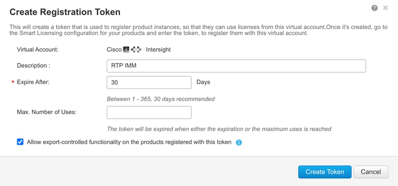
When setting up a new Cisco Intersight account (as discussed in this document), the account needs to be enabled for Cisco Smart Software Licensing.
1. Associate the Cisco Intersight account with Cisco Smart Licensing by following these steps:
◦ Log in to the Cisco Smart Licensing portal: https://software.cisco.com/software/csws/ws/platform/home?locale=en_US#module/SmartLicensing.
◦ Select the correct virtual account.
◦ Under Inventory > General, generate a new token for product registration.
◦ Copy this newly created token.
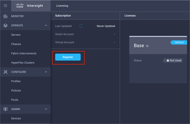
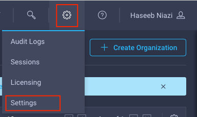
2. With the Cisco Intersight account associated with Cisco Smart Licensing, log in to the Cisco Intersight portal and click Settings (the gear icon) in the top-right corner. Choose Licensing.
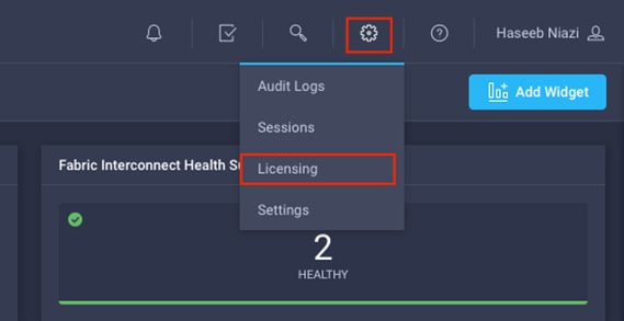
3. Under Cisco Intersight > Licensing, click Register.
4. Enter the copied token from the Cisco Smart Licensing portal.
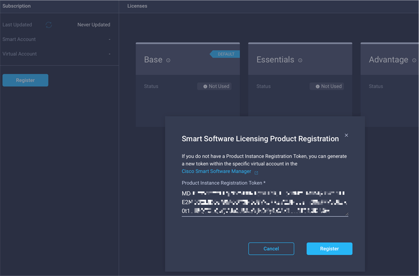
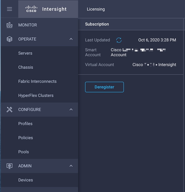
5. Click Register and wait for registration to go through. When the registration is successful, the information about the associated Cisco Smart account is displayed.
6. For all new accounts, the default licensing tier is set to Base. For Cisco Intersight managed mode, the default tier needs to be changed to Essential or a higher tier. To make this change, click Set Default Tier.
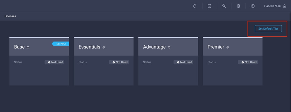
7. Select the tier supported by your Smart License.
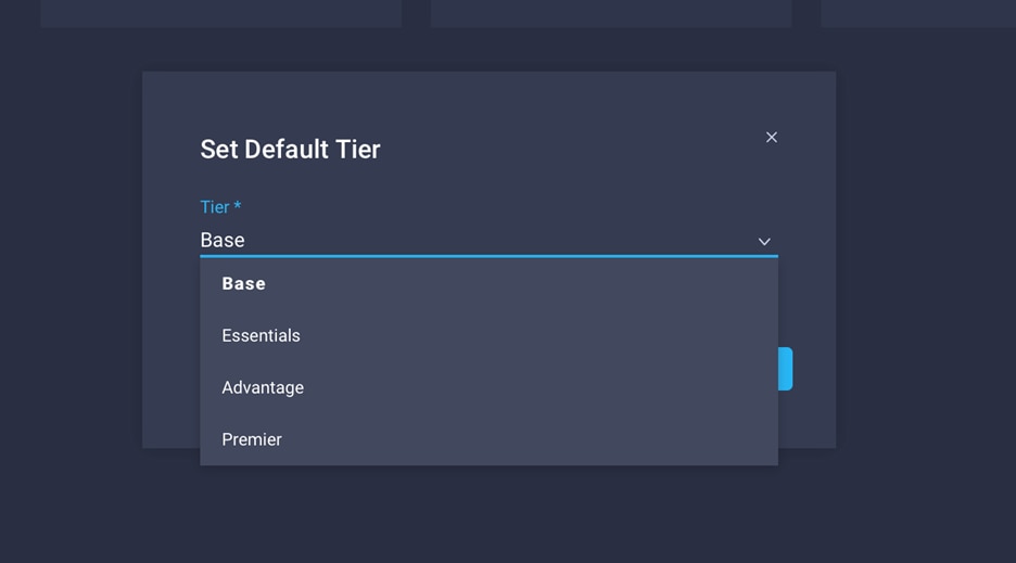
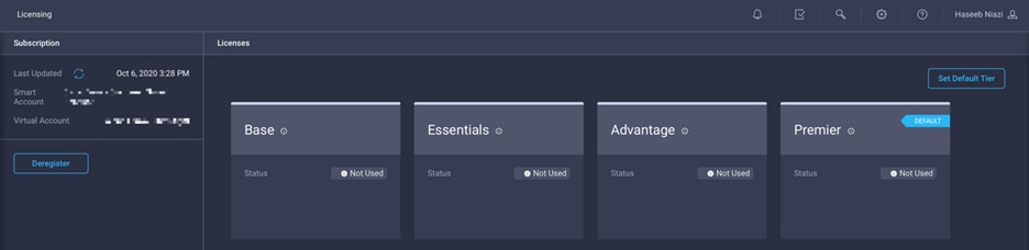
8. In this deployment, the default license tier is set to Premier.
At this time, a known issue occurs: if Cisco UCS was claimed when the license default tier was set to Base (for all new account setups), customers may see error messages when creating certain policies (for example, a domain profile). The following screen image shows such an error message.
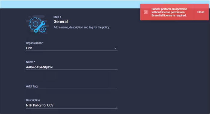
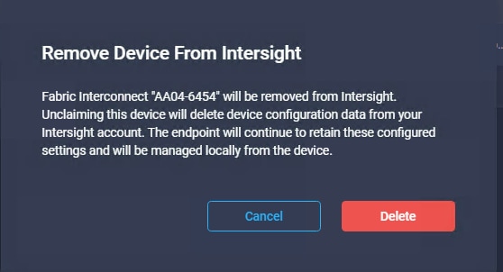
To work around this issue, you need to delete Cisco UCS from the account and then reclaim it after making sure that the correct license tier has been set up as the default. To delete an existing Cisco UCS device, follow these steps:
1. Log in to the Cisco Intersight portal.
2. Go to ADMIN > Devices in the left column and select the device.
3. Click the Delete icon.
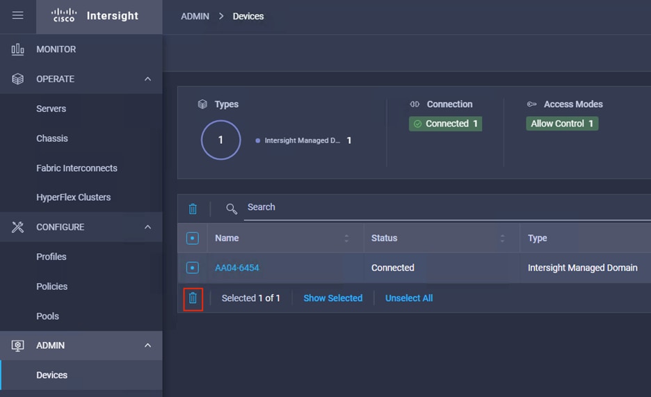
4. Click Delete.
5. Go back to the Cisco UCS device GUI and make sure that the Cisco UCS status has changed to Not Claimed.
6. In the Cisco Intersight portal, click Settings (the gear Icon) in the top-right corner and choose Licensing.
7. Verify that the default licensing tier is set to Essentials (or higher).
8. Go to ADMIN > Targets and click Claim a New Target in the top-right corner.
9. Select Cisco UCS Domain (Intersight Managed).
10. Click Start.
11. Add the device ID and claim code copied from the Cisco UCS device GUI.
12. Click Claim at the bottom right.
Note: This issue is not observed when adding Cisco UCS Manager managed systems or Cisco HyperFlex™ systems to a new or existing Cisco Intersight account.
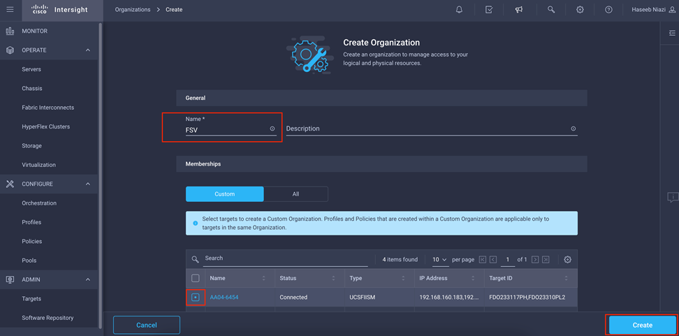
Set up a Cisco Intersight organization
You need to define all Cisco Intersight managed mode configurations for Cisco UCS, including policies, under an organization. To define a new organization, follow these steps:
1. Log in to the Cisco Intersight portal.
2. Click Settings (the gear icon) and choose Settings.
3. Click Organizations in the middle panel.
4. Click Create Organization in the top-right corner.
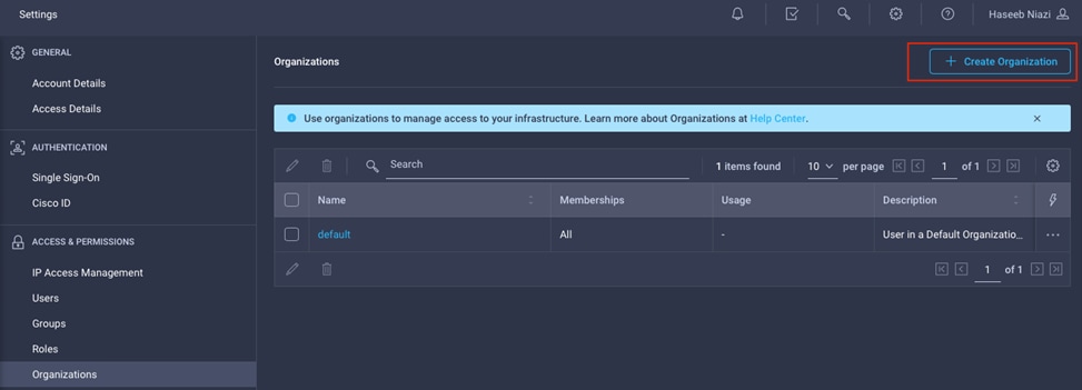
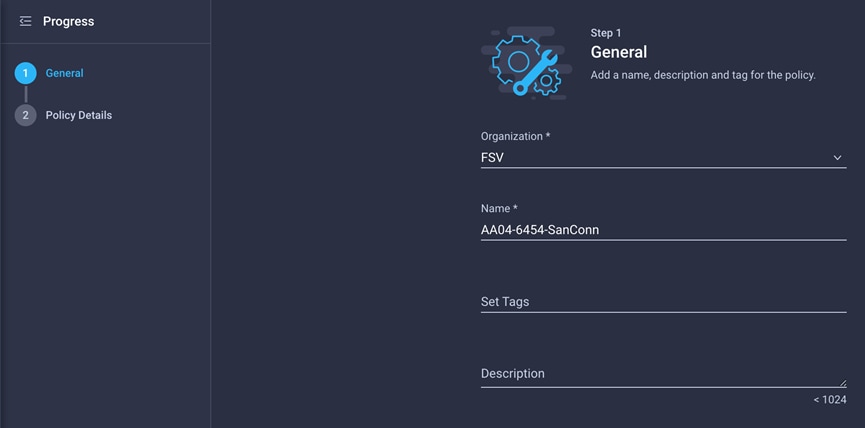
5. Provide a name for the organization (for example, FSV).
6. Under Memberships, select Custom.
7. Select the recently added Cisco UCS device for this organization.
8. Click Create.
Configure a Cisco UCS domain profile
A Cisco UCS domain profile configures a fabric interconnect pair through reusable policies, allows configuration of the ports and port channels, and configures the VLANs and VSANs in the network. It defines the characteristics of and configures ports on fabric interconnects. The domain-related policies can be attached to the profile either at the time of creation or later. One Cisco UCS domain profile can be assigned to one fabric interconnect domain.
To create a Cisco UCS domain profile, follow these steps:
1. Log in to the Cisco Intersight portal
2. Click to expand CONFIGURE in the left pane and select Profiles.
3. In the main window, select UCS Domain Profiles and click Create UCS Domain Profile.
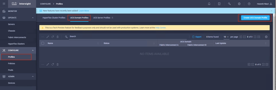
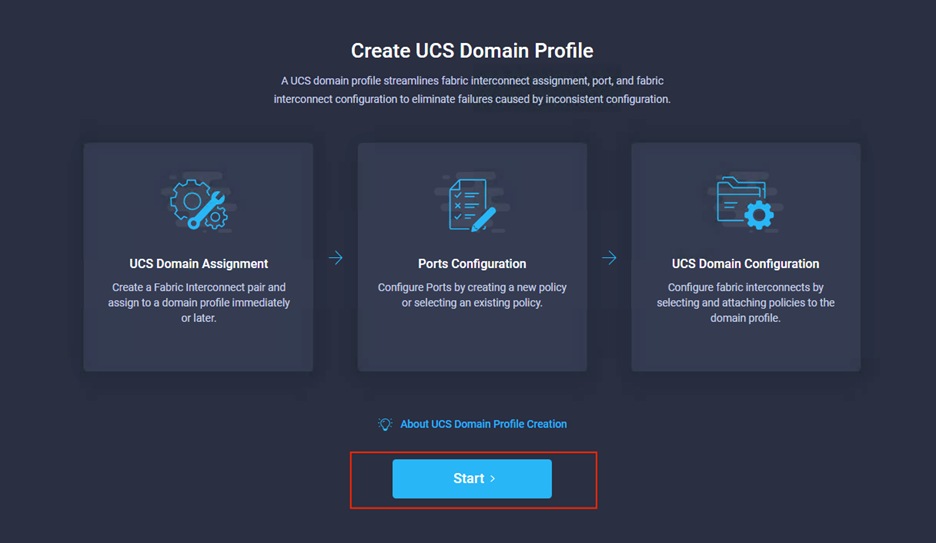
4. On the Create UCS Domain Profile screen, click Start.
Follow these steps for the general configuration:
1. Choose the organization from the drop-down menu (for example, FSV).
2. Provide a name for the domain profile (for example, AA04-6454-DomProf).
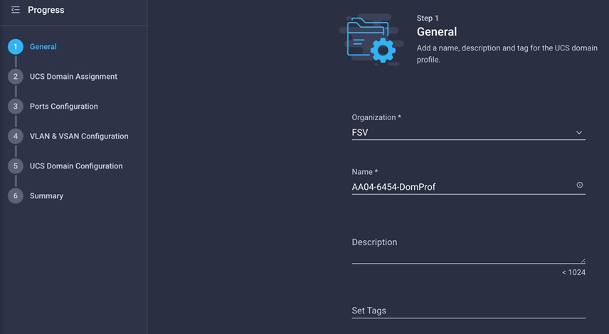
3. Click Next.
Follow these steps for Cisco UCS domain assignment:
1. Assign the Cisco UCS domain to this new domain profile by clicking Assign Now and selecting the previously added Cisco UCS domain (AA04-6454).
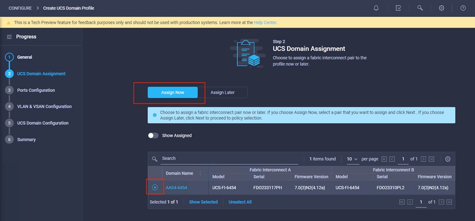
2. Click Next.
Follow these steps to configure the ports:
1. Click Select Policy for Fabric Interconnect A.
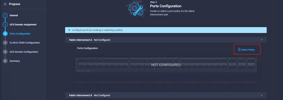
2. Click Create New in the right pane to define new port configuration policy.
Note: This document uses separate port policies for the two fabric interconnects because each fabric interconnect uses unique Fibre Channel and VSAN connections. If boot from SAN were not required, the same port policy could have been reused across the two fabric interconnects.
3. Choose the organization from the drop-down menu.
4. Provide a name for the policy (for example, AA04-6454-A-PortPol).
5. From the drop-down menu, select the correct fabric interconnect model under Switch Model (for example, UCS-FI-6454).
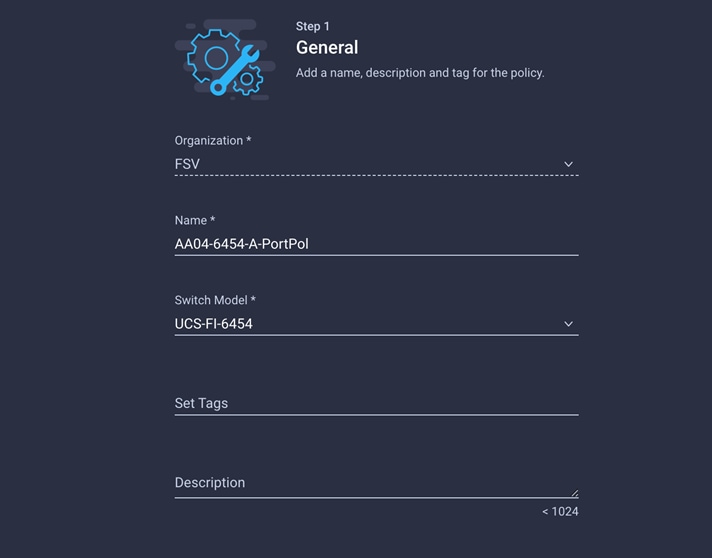
6. Click Next.
7. Move the slider to set up unified ports. In this example, the first four ports were selected as Fibre Channel ports. Click Next.
8. Verify that ports 1 through 4 are configured as Fibre Channel ports.
9. Select all the ports that need to be configured as server ports by clicking the ports in the graphic (or in the list below the graphic). When all ports are selected, click Configure.
10. From the drop-down menu, choose Server as the role. Leave FEC set to Auto and click Save.
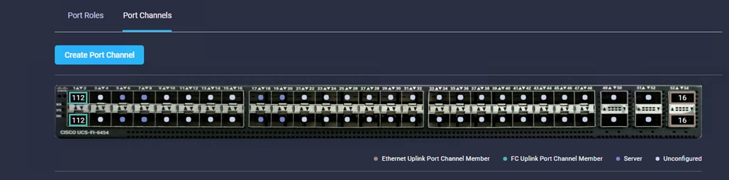
11. Configure an uplink Ethernet port channel by selecting Port Channels in the main pane and then clicking Create Port Channel.
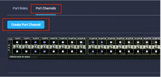
12. Select Ethernet Uplink Port Channel as the role, provide a port-channel ID (for example, 15), and choose a value for Admin Speed (Auto is used here).
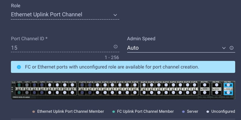
13. Click Save.
14. Configure the Fibre Channel port channel by selecting Port Channel in the main pane again and clicking Create Port Channel.
15. In the drop-down menu under Role, choose FC Uplink Port Channel.
16. Provide a port-channel ID (for example, 111), choose a value for Admin Speed (16Gbps is used here), and provide a VSAN ID (for example, 111).
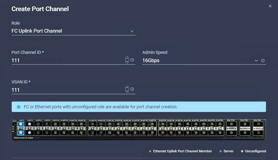
17. Click Save.
18. Verify the port-channel IDs and ports after both the Ethernet uplink port channel and the Fibre Channel uplink port channel have been created.
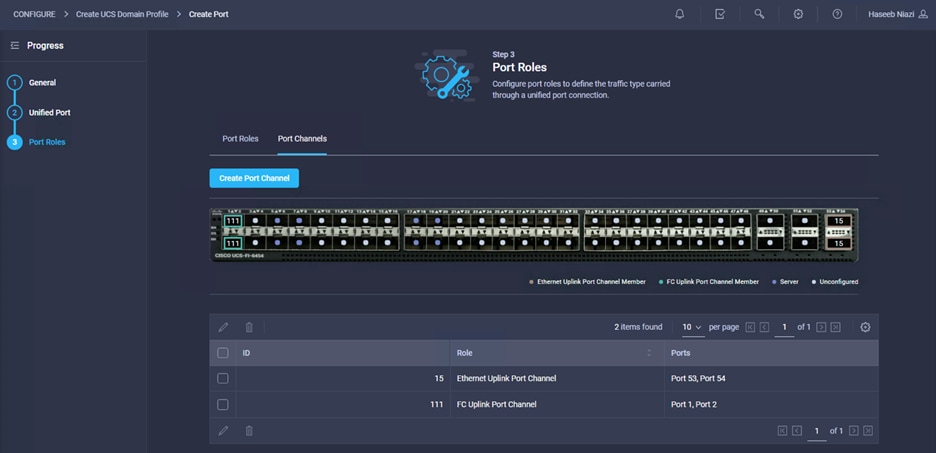
19. Click Save to create the port policy for Fabric Interconnect A. Use the summary screen to verify that the ports were selected and configured correctly.
20. Create policy for Fabric Interconnect B. Click Select Policy for Fabric Interconnect B and, in the pane at the right, click Create New.
21. Verify the organization from the drop-down menu (for example, FSV).
22. Provide a name for the policy (for example, AA04-6454-B-PortPol).
23. Select the correct UCS FI Model under the Switch Model (for example, AA04-6454-B-PortPol).
24. Click Next.
25. Repeat the steps you used for Fabric Interconnect A to configure Fibre Channel ports, server ports, and Ethernet and Fibre Channel port channels with appropriate IDs (for example, Ethernet port-channel ID 16 and Fibre Channel port-channel ID 112).
26. Use the summary screen to verify that the ports were selected and configured correctly for Fabric Interconnect B.
27. When the port configuration for both fabric interconnects is complete and looks good, click Next.
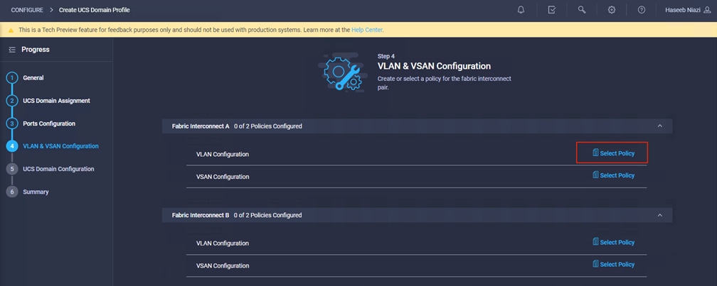
Step 4: VLAN and VSAN Configuration
In this step, a single VLAN policy will be created for both fabric interconnects, but individual policies will be created for the VSANs because the VSAN IDs are unique for each fabric interconnect.
1. Click Select Policy next to VLAN Configuration under Fabric Interconnect A and, in the pane on the right, click Create New.
2. Verify that the correct organization is selected (for example, FSV).
3. Provide a name for the policy (for example, AA04-6454-VLANPol).
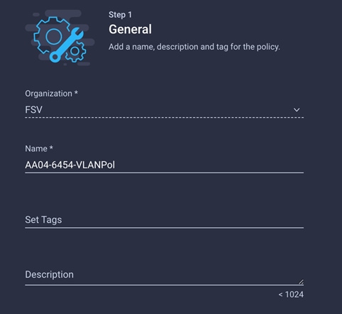
4. Click Next.
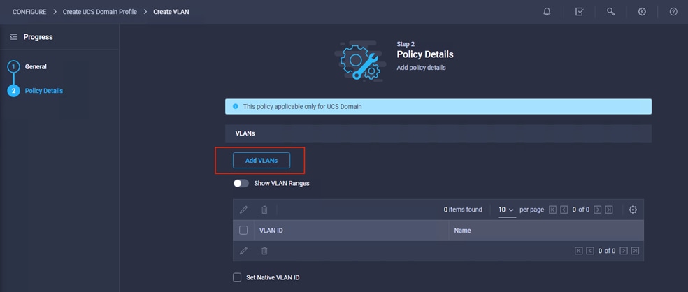
5. Click Add VLANs.
6. Provide a name and VLAN ID for the native VLAN (for example, Native-VLAN and 2).
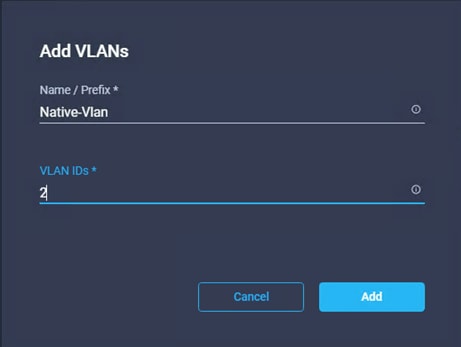
7. Click Add.
8. Select Set Native VLAN ID and specify the VLAN number (for example, 2) under the VLAN ID.
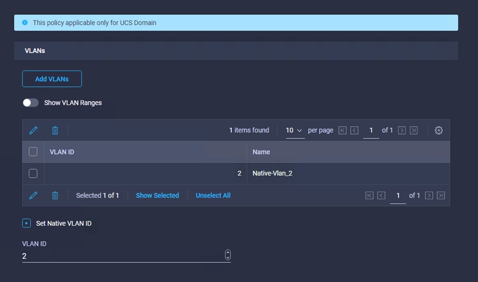
9. Add the remaining VLANs for FlashStack by clicking Add VLANs and entering the VLANs one by one. The VLANs used during this validation are shown in the screen capture here.
10. Click Create at bottom right to create all the VLANs.
11. Click Select Policy next to VLAN Configuration for Fabric Interconnect B and select the same VLAN policy that was created in the previous step.
Follow these steps to create and apply the VSAN policy:
1. Click Select Policy next to VSAN Configuration under Fabric Interconnect A and, in the pane on the right, click Create New.
2. Verify that the correct organization is selected (for example, FSV).
3. Provide a name for the policy (for example, AA04-6454-A-VSANPol).
4. Click Next.
5. Click Add VSAN and provide a name (for example, VSAN-A), VSAN ID (for example, 111), and associated Fibre Channel over Ethernet [FCoE] VLAN ID (for example, 111) for SAN A.
6. Click Add.
7. Enable Uplink Trunking for this VSAN.
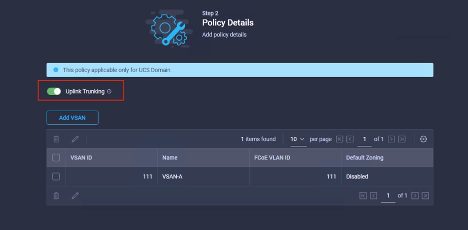
8. Click Create.
9. Repeat the same steps to create a new VSAN policy for SAN B. Click Select Policy next to VSAN Configuration under Fabric Interconnect B and, in the pane on the right, click Create New.
10. Verify that the correct organization is selected (for example, FSV).
11. Provide a name for the policy (for example, AA04-6454-B-VSANPol).
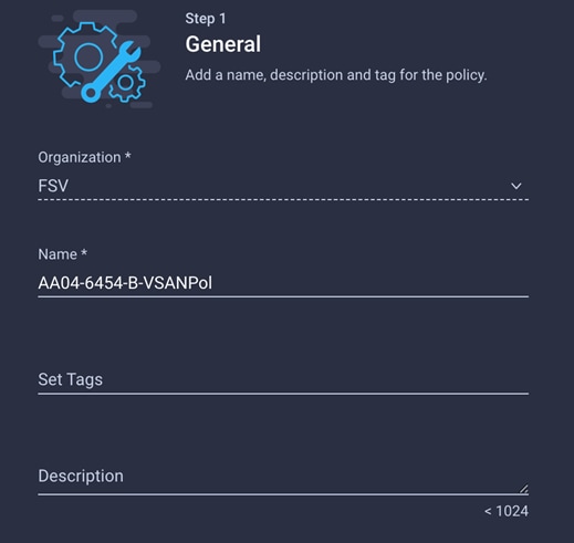
12. Click Next.
13. Click Add VSAN and provide a name (for example, VSAN-B), VSAN ID (for example, 112), and associated FCoE VLAN ID (for example, 112) for SAN B.
14. Click Add.
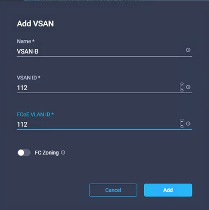
15. Enable Uplink Trunking for this VSAN.
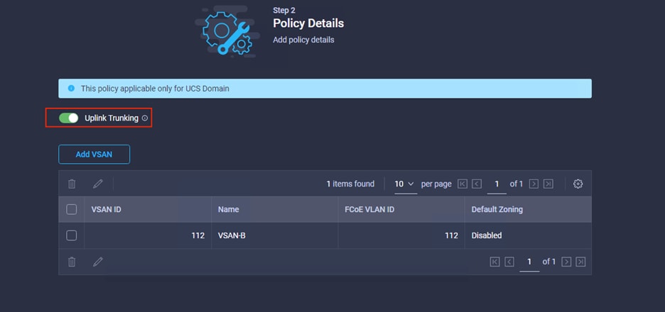
16. Click Create.
17. Verify that a common VLAN policy and two unique VSAN policies are associated with the two fabric interconnects.
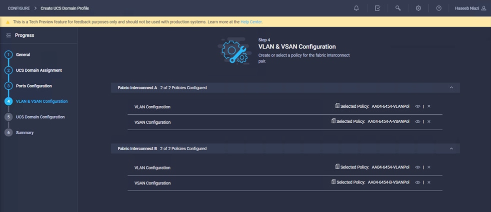
18. Click Next.
Step 5: UCS Domain Configuration
You need to define some additional policies, such as NTP, network connectivity, and system QoS, for the Cisco UCS domain configuration.
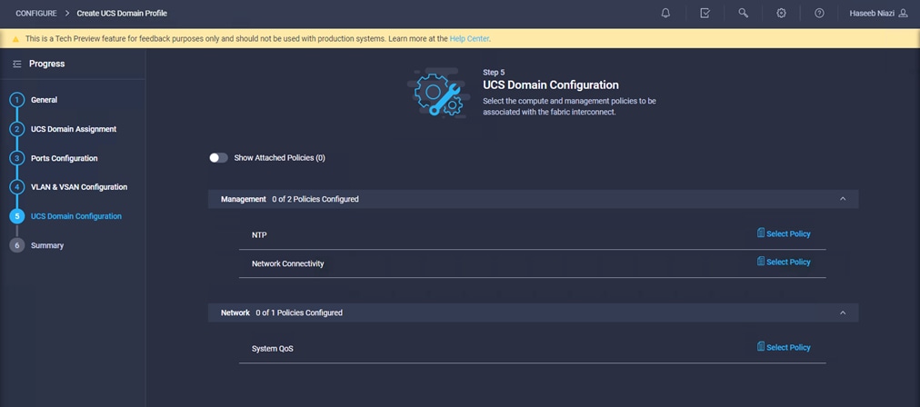
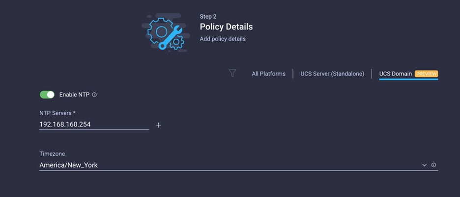
To define an NTP server for the Cisco UCS domain, configure an NTP policy.
1. Click Select Policy next to NTP and, in the pane on the right, click Create New.
2. Provide a name for the policy (for example, AA04-6454-NTPPol).
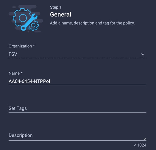
3. Click Next.
4. Enable NTP, provide the NTP server IP addresses (for example, 192.168.160.254), and choose the time zone from the drop-down menu (for example, America/New_York).
5. Click Create.
Define network connectivity policy
To define the Domain Name Service (DNS) servers for Cisco UCS, configure network connectivity policy.
1. Click Select Policy next to Network Connectivity and, in the pane on the right, click Create New.
2. Provide a name for the policy (for example, AA04-6454-NetConnPol).
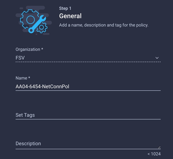
3. Provide DNS server IP addresses for Cisco UCS (for example, 192.168.160.53 and 192.168.160.54).
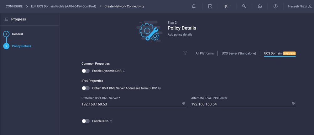
4. Click Create.
To define the QoS settings for Cisco UCS, configure system QoS policy.
1. Click Select Policy next to System QoS and, in the pane on the right, click Create New.
2. Provide a name for the policy (for example, AA04-6454-SystemQoSPol).
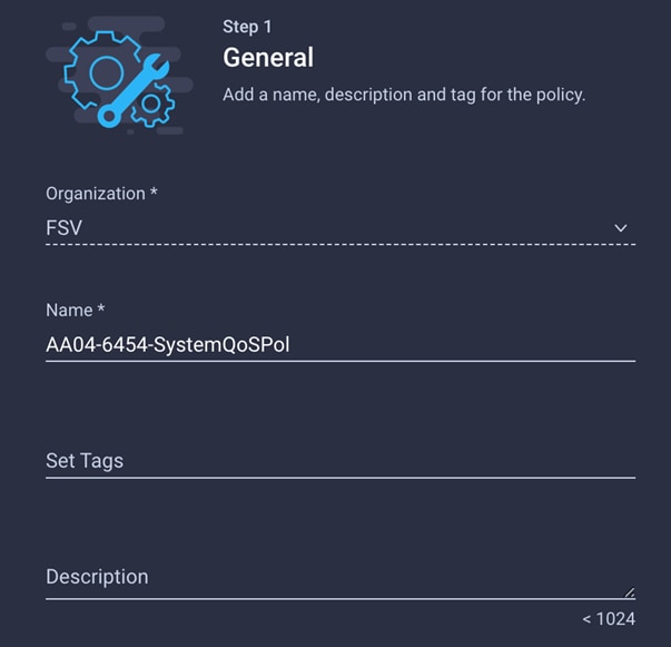
3. Keep the default selections, or change the parameters if necessary.
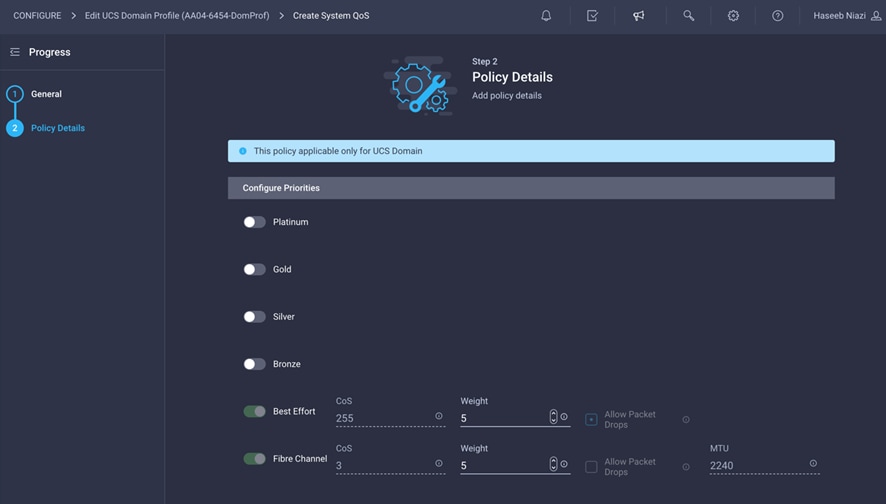
4. Click Create.
5. Click Next.
Verify all the settings (be sure to expand the fabric interconnect settings to verify them) and make sure that the configuration is correct.
Deploy the Cisco UCS domain profile
Now deploy the Cisco UCS domain profile.
1. After verifying the configuration, click Deploy.
2. Acknowledge the warning and click Deploy again.
It will take some time to validate and configure the settings on the fabric interconnects. You can log into the terminal and console servers to see when the Cisco UCS fabric interconnects have finished being configured and have been successfully rebooted.
When the Cisco UCS domain profile has been successfully deployed, the Cisco UCS chassis and the blades should be successfully discovered.
1. Log in to the Cisco Intersight portal. Under CONFIGURE > Profiles > UCS Domain Profiles, verify that the domain profile has been successfully deployed.
2. Under OPERATE > Chassis, verify that the chassis has been discovered and is visible.
3. Under OPERATE > Servers, verify that the servers have been successfully discovered and are visible.
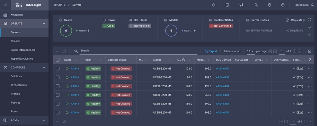
In Cisco Intersight, a server profile enables resource management by simplifying policy alignment and server configuration. You can create server profiles using the Server Profile wizard to provision servers, create policies to help ensure smooth deployment of servers, and eliminate failures that are caused by inconsistent configurations. After creating server profiles, you can edit, clone, deploy, or unassign them as required.
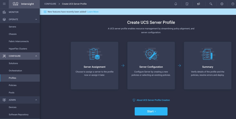
To configure a server profile, follow these steps:
1. Log in to the Cisco Intersight portal.
2. Go to Configure > Profiles and, from the main window select UCS Server Profile.
3. Click Create UCS Server Profile.
4. Click Start.
Perform the following steps to create the general configuration:
1. Select the organization from the drop-down menu (for example, FSV).
2. Provide a name for the server profile (for example, SP-FlashStack-01).
3. Select UCS Server (FI-Attached).
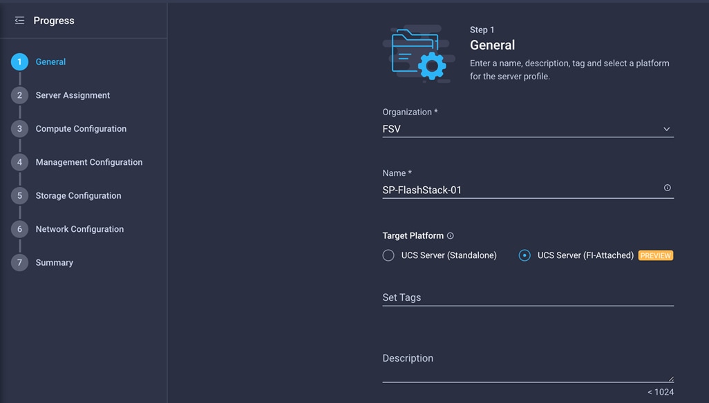
4. Click Next.
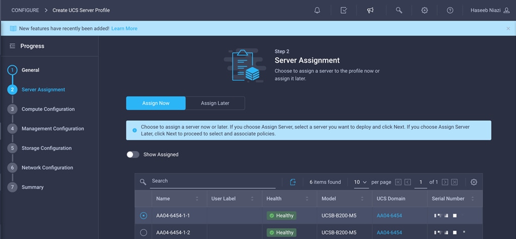
Next, set the server assignment.
1. Make sure that server assignment is set to Assign Now.
2. Select a server (for example, AA06-6454-1) and click Next.
Now define the computing configuration.
First configure BIOS policy.
1. Click Select Policy next to BIOS Configuration and in the pane on the right, click Create New.
2. Provide a name for the policy (for example, AA04-6454-BiosPol).
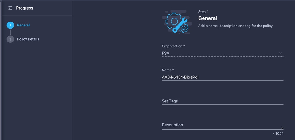
3. Click Next.
4. Select appropriate values on the Policy Details screen.
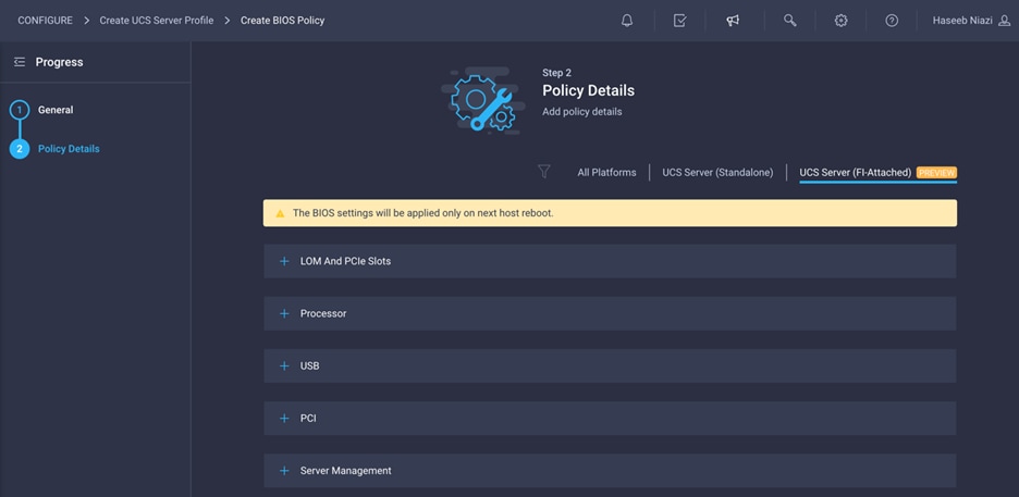
The following values were selected during the validation process described in this document to match the Cisco Validated Designs for FlashStack:
● LOM and PCIe Slots > CDN Support for LOM: Enabled
● Processor > DRAM Clock Throttling: Performance
● Processor > Freq Floor Override: Enabled
● Processor > CPU C State: Disabled
● Processor > Processor C1E: Disabled
● Processor > Processor C3 Report: Disabled
● Processor > Processor C6 Report: Disabled
● Processor > Power Technology: Custom
● Processor > Energy Performance: Performance
● Memory > NVM Performance Setting: Balanced Profile
● Memory > Memory RAS Configuration: Maximum Performance
Note: A few BIOS settings (Enable Quiet Boot and Processor C7 Report) are not available at this time and cannot be configured.
5. Click Create.
Next, configure boot-order policy.
1. Click Select Policy next to BIOS Configuration and, in the pane on the right, click Create New.
2. Provide a name for the policy (for example, AA04-FS-BootPol).

3. Click Next.
4. For Configure Boot Mode, select Unified Extensible Firmware Interface (UEFI).
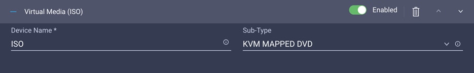
5. From the Add Boot Device drop-down menu, choose Virtual Media.
6. Provide a device name (for example, ISO), and for Sub-Type choose KVM Mapped DVD.
Here, all four Pure Storage Fibre Channel interfaces will be added as boot options. The four interfaces are named as follows:
● FlashArray-CT0FC0: FlashArray Controller 0, FC0 (SAN A)
● FlashArray-CT1FC0: FlashArray Controller 1, FC0 (SAN A)
● FlashArray-CT0FC1: FlashArray Controller 0, FC1 (SAN B)
● FlashArray-CT1FC1: FlashArray Controller 1, FC1 (SAN B)
7. From the Add Boot Device drop-down menu, choose SAN Boot.
8. Provide a device name (for example, FlashArray-CT0FC0) and logical unit number (LUN) value (for example, 1).
9. Provide an interface name (for example, vHBA-A) and note this name to be used for vHBA definition later. This value is important and should match the vHBA name.
10. Add the appropriate WWPN value in the target WWPN. You can obtain this value from the Pure Storage FlashArray by using the pureport list command.
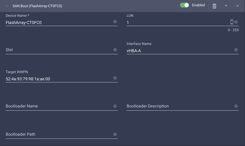
11. Click Create.
12. Repeat these steps three more times to add all the FlashArray interfaces. You can rearrange the policies using the arrow keys (if needed) to change the boot order.
13. After all the boot devices have been added, you can view the list, as shown in the example here.
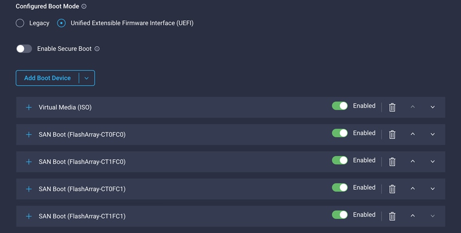
14. Click Next.
Step 4: Management Configuration
You will next configure management policy.
Configure Cisco IMC access policy
Use the following steps to configure IMC access policy:
1. Click Select Policy next to IMC Access and, in the pane on the right, click Create New.
2. Provide a name for the policy (for example, AA04-6454-IMCPol).
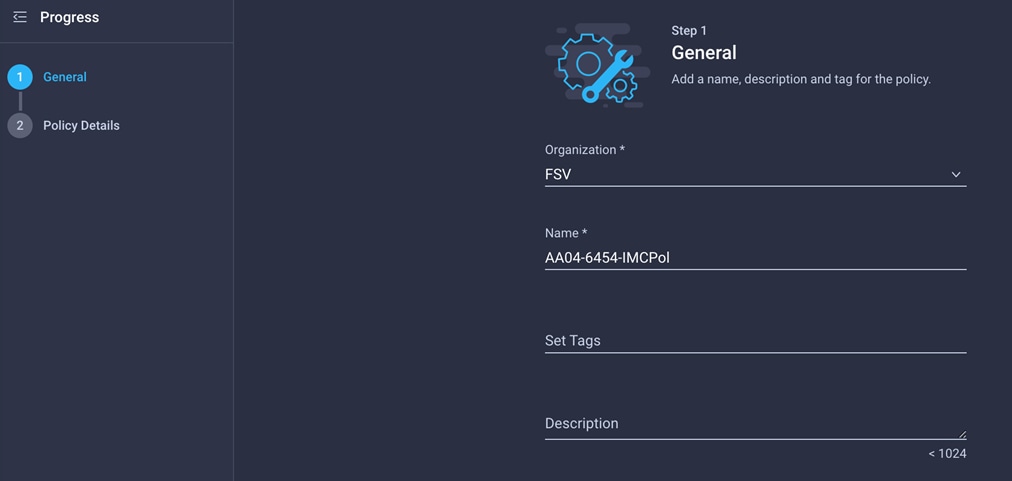
3. Click Next.
4. Provide the in-band (or out-of-band) management VLAN ID (for example, 511)
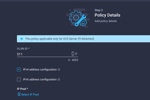
5. Select “IPv4 address configuration” and select IP Pool to define a KVM IP address assignment pool.
6. Click Create New on the right.
7. Provide a name for the policy (for example, AA04-6454-Pool).
8. Select Configure IPv4 Pool and provide the information to define a pool for KVM IP address assignment.
Note: The management IP pool subnet should be accessible from the host trying to open the KVM connection. In the example here, the hosts trying to open a KVM connection would need to be able to route to the 192.168.160.0 subnet.
9. Click Next.
10. Unselect Configure IPv6 Pool.
11. Click Create to finish configuring the IP address pool.
12. Click Create to finish configuring the IMC access policy.
Now configure local user policy.
1. Click Select Policy next to Local User and, in the pane on the right, click Create New.
2. Provide a name for the policy (for example, AA04-6454-LocalUser-Pol).

3. Verify that UCS Server (FI-Attached) is selected.
4. Verify that Enforce Strong Password is selected.
5. Click Add New User.
6. Provide the username (for example, fsadmin), the role (for example, admin), and the password.
Note: The username and password combination defined here will be used to log in to KVMs. The typical Cisco UCS admin username and password combination cannot be used for KVM access.
7. Click Create to finish configuring the user.
8. Click Create to finish configuring local user policy.
9. Click Next.
Click Next for Storage Configuration (you will not make any changes).
Step 6a: Network Configuration—LAN connectivity policy
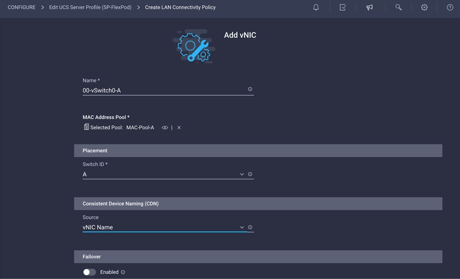
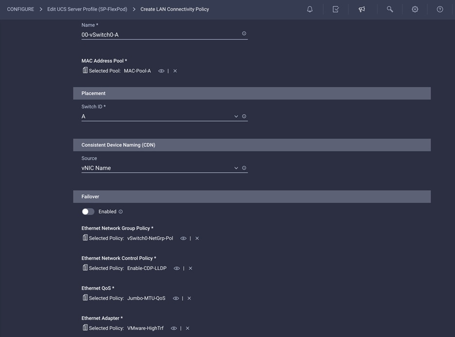
The LAN connectivity policy determines the connections and the network communication resources between the server and the LAN on the network. These policies use pools to assign MAC addresses to servers and to identify the vNICs that the servers use to communicate with the network.
1. Click Select Policy next to LAN Connectivity and, in the pane on the right, click Create New.
2. Provide a name for the policy (for example, AA04-6454-LanConn).
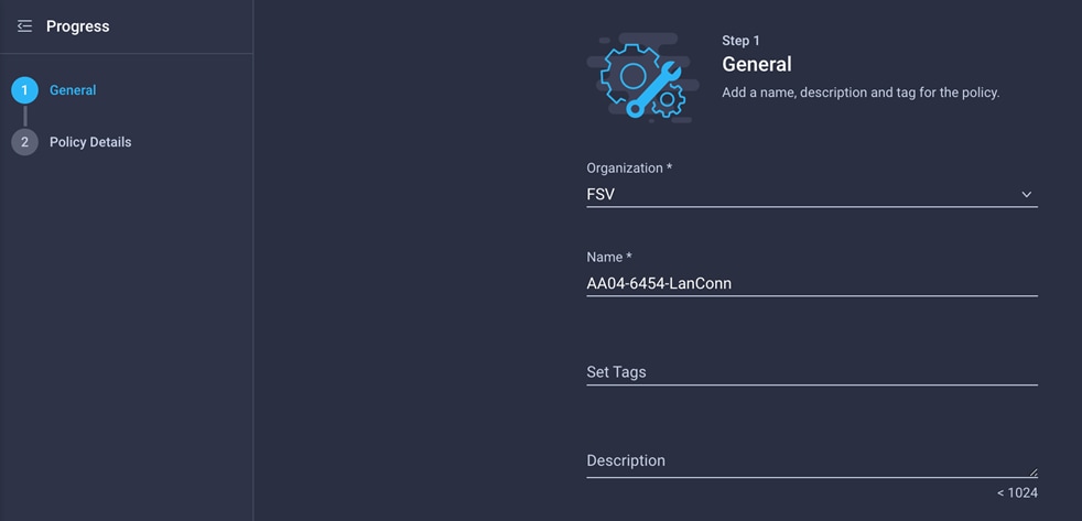
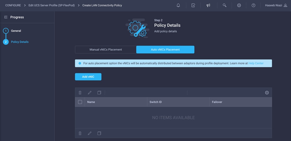
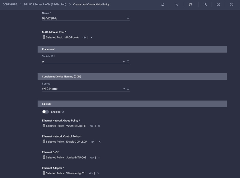
In this deployment, four vNICs are used, as follows:
● 00-vSwitch0-A: Fabric Interconnect A vNIC; assigned to the vSwitch for management VLANs
● 01-vSwitch0-B: Fabric Interconnect B vNIC; assigned to the vSwitch for management VLANs
● 02-VDS0-A: Fabric Interconnect A vNIC; assigned to the VDS for VMware vMotion and traffic VLANs
● 03-VDS0-B: Fabric Interconnect B vNIC; assigned to the VDS for VMware vMotion and traffic VLANs
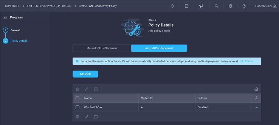
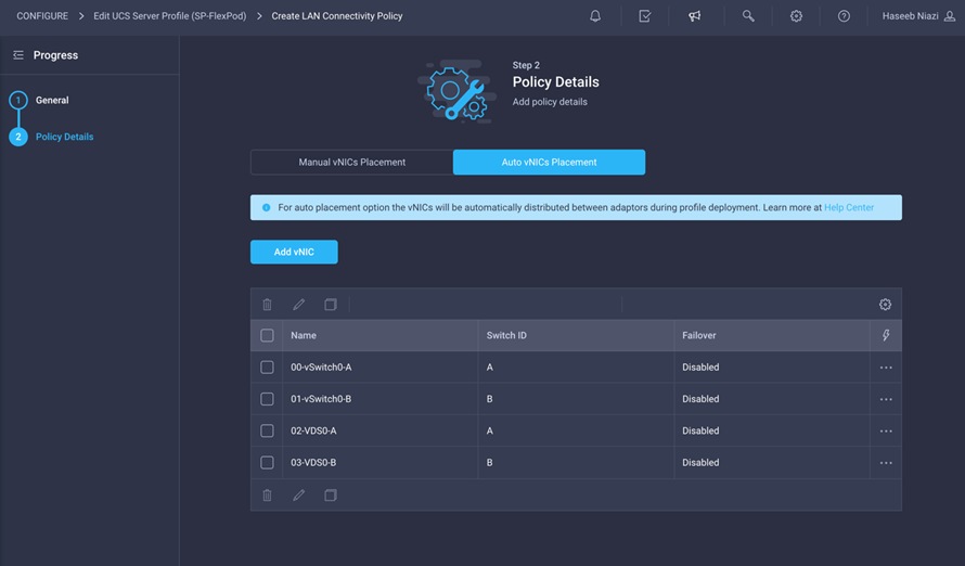
3. To keep the vNIC placement simple, select Auto vNIC Placement.
4. Click Add vNIC.
5. Provide the name of the vNIC (for example, 00-vSwitch0-A).
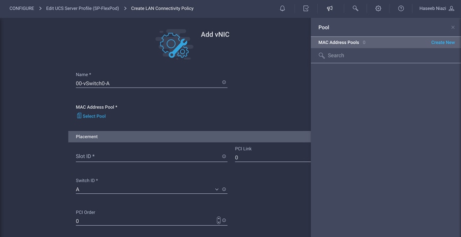
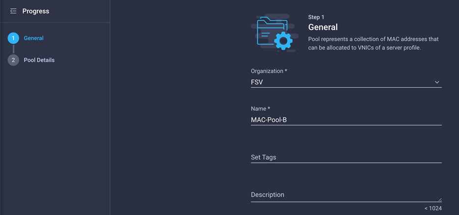
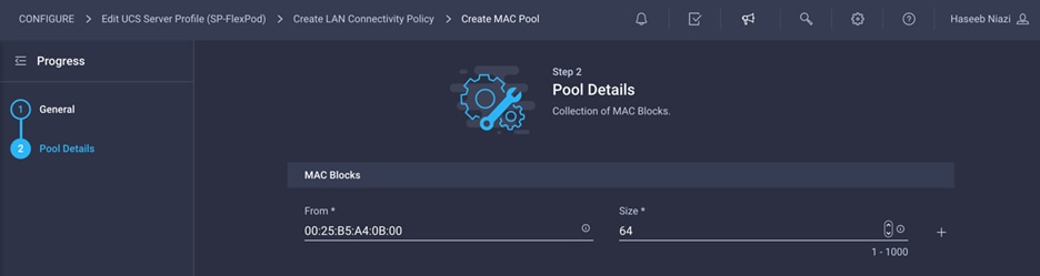
The MAC address pool has not been defined yet, so you will create a new MAC address pool for Fabric A. This pool will be reused for all Fabric A vNICs.
1. Click Select Pool under MAC Address Pool and, in the pane on the right, click Create New.
2. Provide a name for the policy (for example, MAC-Pool-A).

3. Click Next.
4. Provide the starting MAC address. The recommended prefix for MAC addresses is 00:25:B5:xx:xx:xx. As a best practice, some additional information is always coded into the MAC address pool for ease of troubleshooting. For example, ion the Pool Details screen shown here, A4 represents the rack ID and 0A represents Fabric A.
5. Provide the size of the MAC address pool (for example, 64).
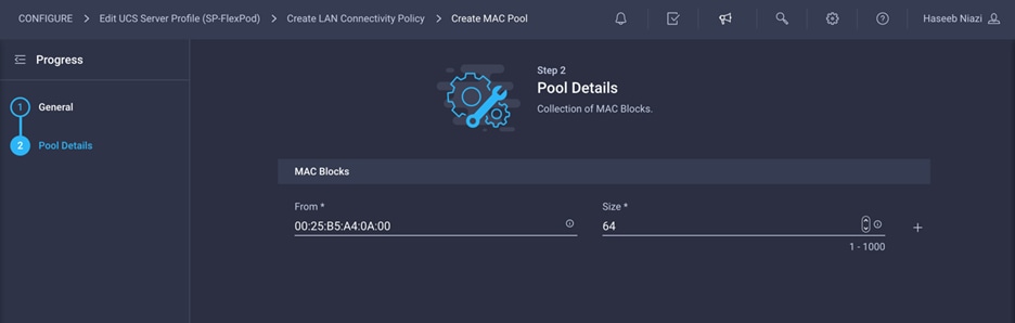
6. Click Create to finish creating the MAC address pool.
7. Back in the Add vNIC window, from the drop-down menu choose A as the switch ID.
8. From the drop-down menu, choose vNIC Name for Consistent Device Naming (CDN).
9. Be sure that Failover is disabled. Failover will be supported by attaching multiple NICs to the VMware vSwitches and VDSs.
Configure Ethernet network group policy
Ethernet policies have not been created yet, so these policies will be created next. These policies will be reused to define additional vNICs. Start by configuring Ethernet network group policy.
Ethernet network group policy defines the VLANs allowed for a particular vNIC. Two network group policies are defined for this deployment:
● vSwitch0 network group policy, to define the VLANs for vSwitch0 (management traffic)
● VDS network group policy, to define the VLANs for VDS (application and vMotion traffic)
1. Click Select Policy under Ethernet Network Group Policy and, in the pane on the right, click Create New.
2. Provide a name for the policy (for example, vSwitch0-NetGrp-Pol).
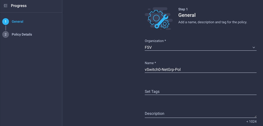
3. Click Next.
4. Enter the allowed VLANs (for example, 2,11,511) and the native VLAN ID (for example, 2).
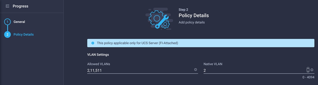
5. Click Create to finish configuring the Ethernet network group policy.
Configure Ethernet network control policy
Ethernet network control policy is used to enable Cisco Discovery Protocol and Link Layer Discovery Protocol (LLDP) for the vNICs. Here, a single policy will be created and reused for all the vNICs.
1. Click Select Policy under Ethernet Network Control Policy and, in the pane on the right, click Create New.
2. Provide a name for the policy (for example, Enable-CDP-LLDP).
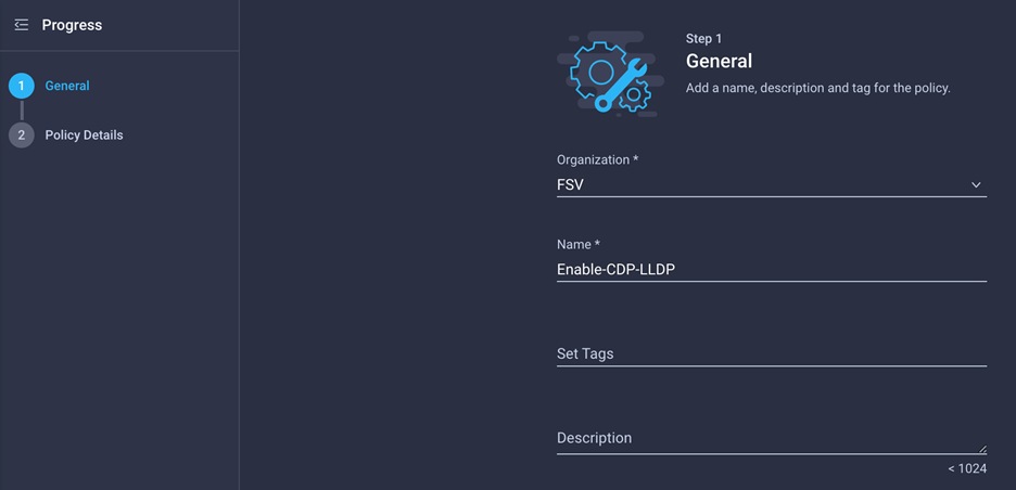
3. Click Next.
4. Enable Cisco Discovery Protocol (CDP) and both transmit and receive under LLDP.
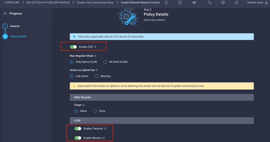
5. Click Create to finish creating Ethernet network control policy.
Ethernet QoS policy is used to enable jumbo maximum transmission unit (MTU) settings for all the vNICs. Here, a single policy will be created and reused for all the vNICs.
1. Click Select Policy under Ethernet QoS and, in the pane on the right, click Create New.
2. Provide a name for the policy (for example, Jumbo-MTU-QoS).
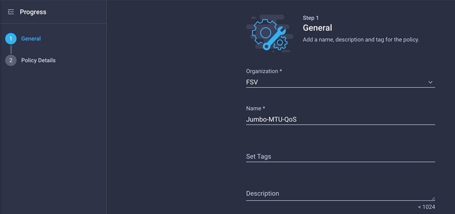
3. Click Next.
4. Change the MTU, Bytes setting to 9000.
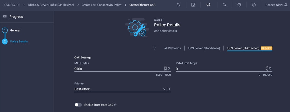
5. Click Create to finish setting up the Ethernet QoS policy.
Configure Ethernet adapter policy
Ethernet adapter policy is used to set the interrupts as well as send and receive queues. Set the values according to the best practices guidance for the operating system in use.
1. Click Select Policy under Ethernet Adapter and in the pane on the right, click Create New.
2. Provide a name for the policy (for example, VMware-HighTrf).
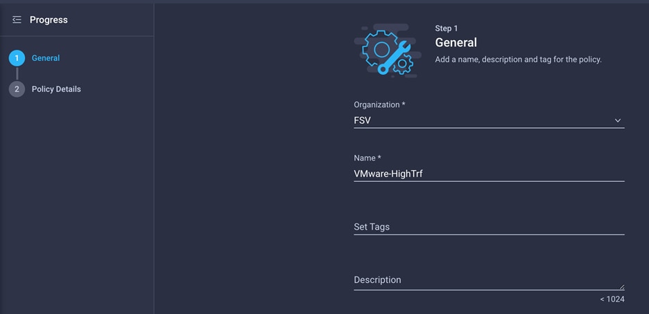
3. Change the Interrupts, Receive Queue Count, Transmit Queue Count, and Completion Queue Count settings as shown on the Policy Details screen here.
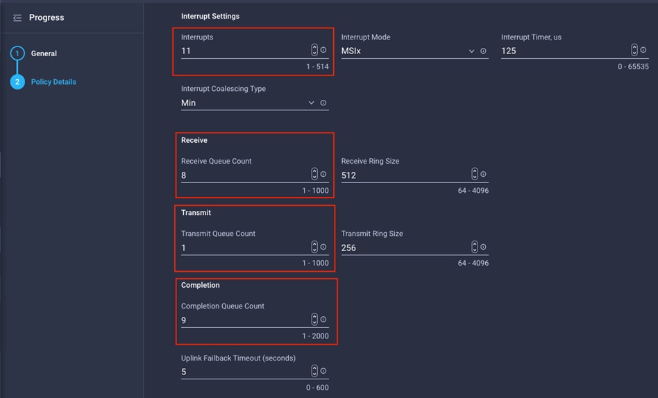
4. Click Create.
Verify the configuration and add the vNIC
Complete the configuration for the vNIC.
1. Verify that all the policies are assigned to vNIC 00-vSwitch0-A.
2. Click Add to add the vNIC.
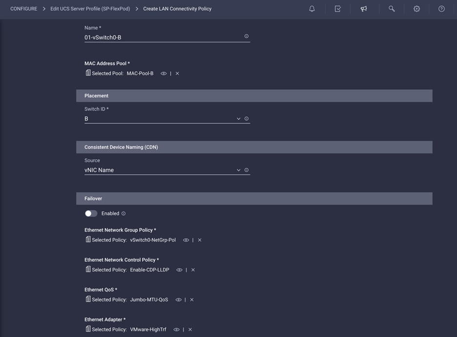
Repeat the previous steps under Step 6a: Network Configuration to create additional vNICs. Most of the policies created for the first vNIC can be reused for the remaining vNICs. The MAC-Pool-B and VDS0-NetGrp-Policy configurations used for subsequent vNICs are described in the following sections.
MAC-Pool-B is used by vNICs 01-vSwitch0-B and 03-VDS0-B.
1. To add the vNIC 01-vSwitch0-B, click Select Pool under MAC Address Pool and click Create New in the pane on the right.
Although the same prefix, 00:25:B5:A4, is used for MAC Address Pool B as for MAC Address Pool A, 0B in the second-to-last octet signifies that these MAC addresses are assigned to vNICs associated with Fabric B.
2. Use the settings shown in the following screen image to configure 01-vSwitch0-B.
Configure network group policy for VDS0
Network group policy for vNICs 02-VDS0-A and 03-VDS0-B differs because the VLANs used for the VDS are different.
1. The network group policy for VDS0 can be defined when adding the 02-VDS0-A vNIC. Instead of selecting the preexisting network group policy, select Create New in the pane on the right.
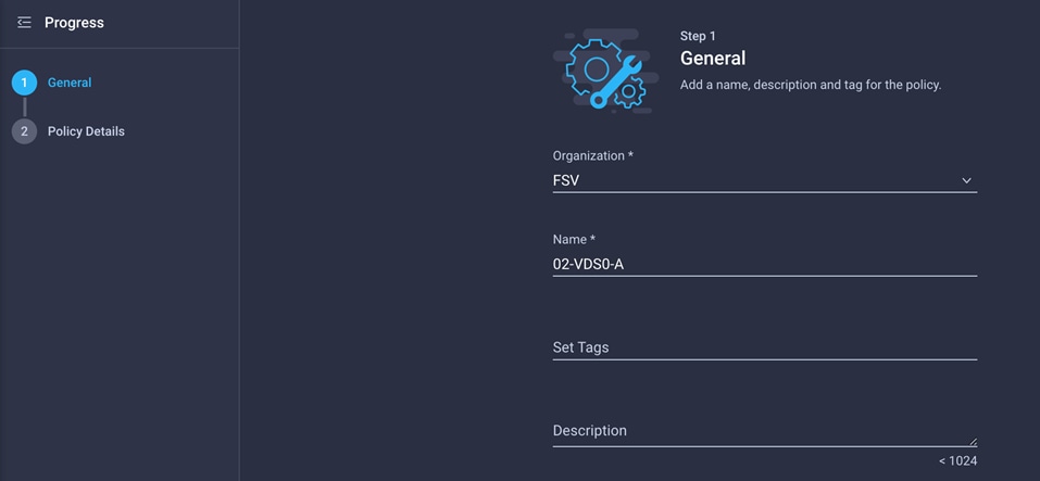
2. Define the correct VLANs associated with the VDS (application traffic and vMotion traffic).
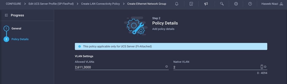
The following screen image shows the settings for vNIC 02-VDS0-A.
The following screen image shows the settings for vNIC 03-VDS0-B.
Verify the configuration and add the vNICs
Complete the configuration for the vNICs.
1. Verify that all the vNICs are added successfully before moving on to SAN connectivity policies.
2. Click Create.
Step 6b: Network Connectivity—SAN connectivity policy
A SAN connectivity policy determines the network storage resources and the connections between the server and the storage device on the network. This policy enables you to configure vHBAs that the servers use to communicate with the SAN
1. Click Select Policy next to SAN Connectivity and, in the pane on the right, click Create New.
2. Provide a name for the policy (for example, AA04-6454-SanConn).
In this deployment, two vHBAs are deployed, as follows:
vHBA-A: Fabric Interconnect A vHBA for SAN A
vHBA-B: Fabric Interconnect B vHBA for SAN B
3. To keep the vHBA placement simple, select Auto vHBAs Placement.
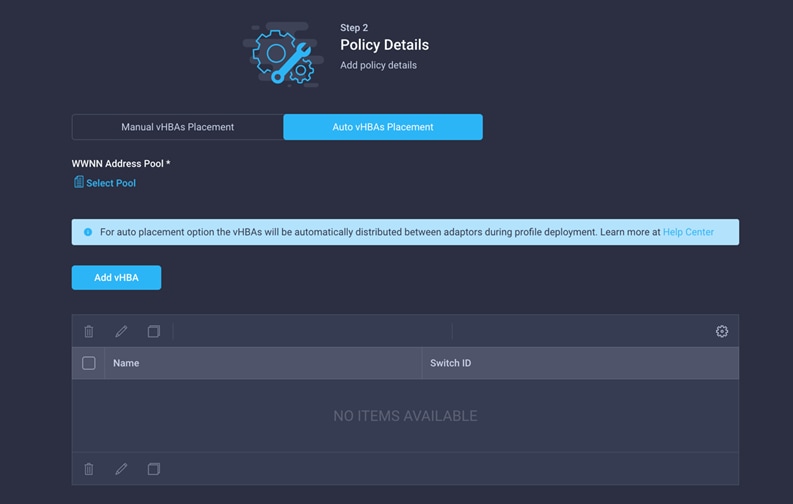
A World Wide Node Name (WWNN) address pool has not been defined yet, so the next step is to create a new WWNN address pool.
1. Click Select Pool under WWNN Address Pool and, in the pane on the right, click Create New.
2. Provide a name for the policy (for example, WWNN-Pool).
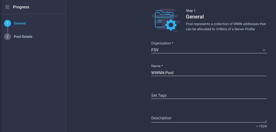
3. Click Next.
4. Provide the starting WWNN block address. The recommended prefix for WWNN addresses is 20:00:00:25:B5:xx:xx:xx. As a best practice, some additional information is always coded into the WWNN address pool for ease of troubleshooting. For example, on the Pool Details screen image here, A4 is the rack ID.
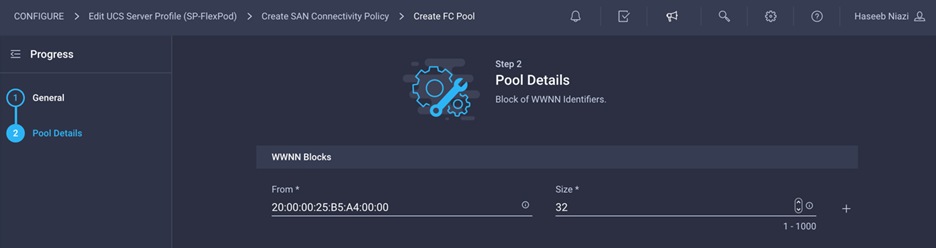
5. Click Create to finish creating the WWNN address pool.
Now create the vHBA for SAN A.
1. Click Add vHBA.
2. Provide the name of the vNIC (for example, vHBA-A).
3. For the vHBA type, choose fc-initiator from the drop-down menu.
4. Choose switch ID A from the drop-down menu.
Create the WWPN pool for SAN A
The WWPN address pool has not been defined yet, so the next step is to create a WWPN address pool for Fabric A.
1. Click Select Pool under WWPN Address Pool and, in the pane on the right, click Create New.
2. Provide a name for the policy (for example, WWPN-Pool-A).
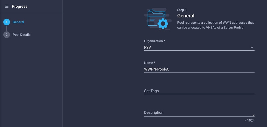
3. Provide the starting WWPN block address for SAN A. The recommended prefix for WWPN addresses is 20:00:00:25:B5:xx:xx:xx. As a best practice, in FlashStack some additional information is always coded into the WWPN address pool for ease of troubleshooting. For example, on the Pool Details screen shown here, A4 is the rack ID, and 0A signifies SAN A.
4. Provide the size of the pool (for example, 32).
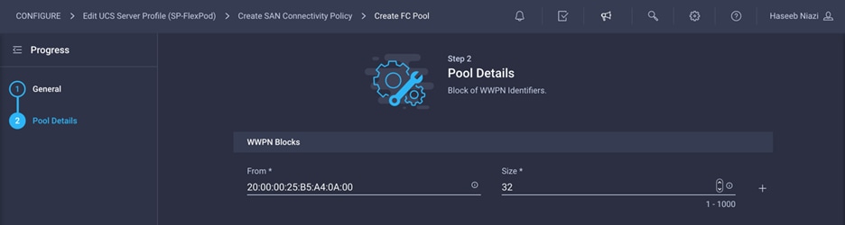
5. Click Create.
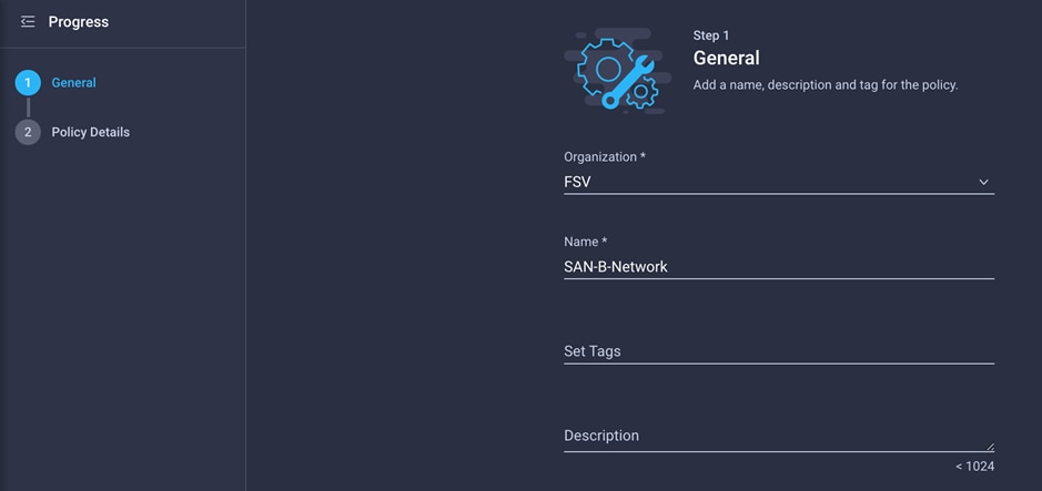
Configure Fibre Channel network policy for SAN A
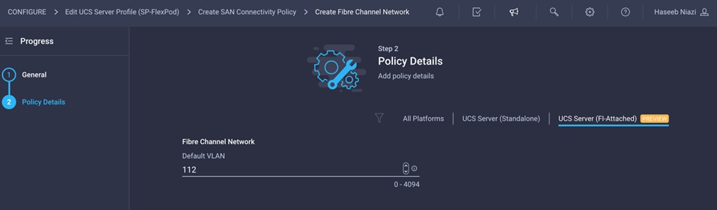
A Fibre Channel network policy governs the virtual SAN (VSAN) configuration for the virtual interfaces. VSAN 111 will be used for vHBA-A, and VSAN 112 will be used for vHBA-B.
1. Click Select Policy under Fibre Channel Network and, in the pane on the right, click Create New.
2. Provide a name for the policy (for example, SAN-A-Network).
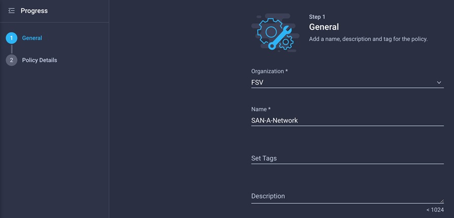
3. For the scope, select UCS Server (FI-Attached).
4. Enter the VSAN information (for example, 111) under Default VLAN.
Note: The current GUI shows Default VLAN instead of Default VSAN. Enter the VLAN associated with VSAN-A.
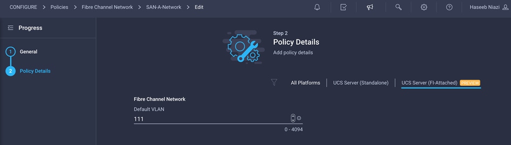
5. Click Create to finish creating the Fibre Channel network policy.
Configure Fibre Channel QoS policy
The Fibre Channel QoS policy assigns a system class to the outgoing traffic for a vHBA. This system class determines the quality of service for the outgoing traffic. The Fibre Channel QoS policy used in this deployment uses default values and will be shared by vHBA-A and vHBA-B.
1. Click Select Policy under Fibre Channel QoS and, in the pane on the right, click Create New.
2. Provide a name for the policy (for example, FC-QoS).
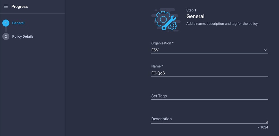
3. For the scope, select UCS Server (FI-Attached).
4. Do not change the default values.
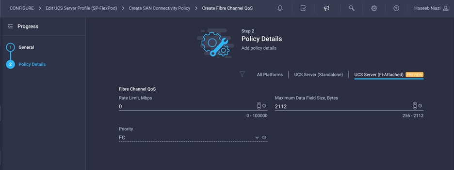
5. Click Create to finish creating the Fibre Channel QoS policy.
Configure Fibre Channel adapter policy
A Fibre Channel adapter policy governs the host-side behavior of the adapter, including the way that the adapter handles traffic. This validation uses the default values for the adapter policy, and the policy will be shared by vHBA-A and vHBA-B.
1. Click Select Policy under Fibre Channel Adapter and, in the pane on the right, click Create New.
2. Provide a name for the policy (for example, FC-Adapter).
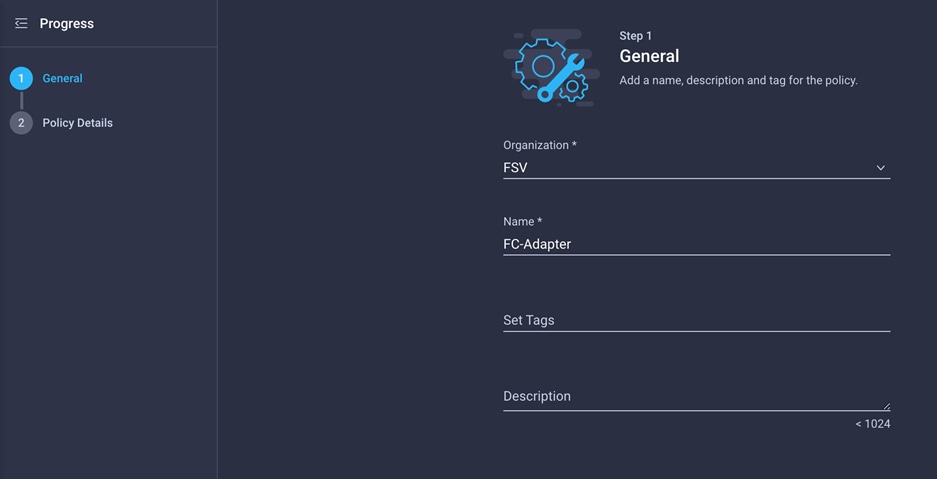
3. For the scope, select UCS Server (FI-Attached).
4. Do not change the default values.
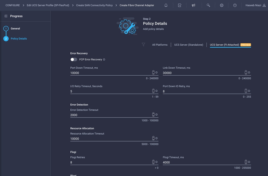
5. Click Create to finish creating the Fibre Channel adapter policy.
6. Click Add to create vHBA-A.
Repeat the preceding steps to add vHBA-B for SAN B. Select switch ID B for this vHBA. The WWPN pool and Fibre Channel network policy (VSAN) for this vHBA are unique, but the Fibre Channel QoS and Fibre Channel adapter policies defined for vHBA-A will be reused. The WWPN and Fibre Channel network information used in this validation for WWPN-Pool-B is shown here for your reference.

The recommended prefix for WWPN addresses is 20:00:00:25:B5:xx:xx:xx. As a best practice, in FlashStack some additional information is always coded into the WWPN address pool for ease of troubleshooting. For example, on the Pool Details screen shown here, A4 is the rack ID, and 0B signifies SAN B.

Configure Fibre Channel network policy for SAN B
Now create the Fibre Channel network policy for SAN B.
1. For the Fibre Channel network policy, use VSAN 112 for vHBA-B.
2. For the scope, select UCS Server (FI-Attached) and enter the VSAN information (for example, 112) under Default VLAN.
Note: The current GUI shows Default VLAN instead of Default VSAN. Enter the VLAN associated with VSAN-B.
3. After adding all the vNICs and vHBAs, verify their placement by expanding the vNIC & vHBA Placement option.
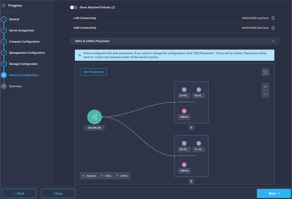
4. Click Next.
On the Summary screen, you can verify which policies are mapped to various settings and the status of the server profile. Because the server profile has not been deployed yet, the status will be Not Deployed.
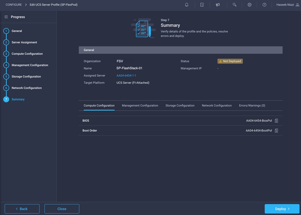
You are ready to deploy the server profile.
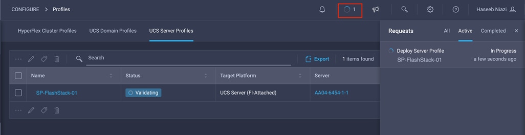
1. After verifying the settings on the server profile Summary screen, click Deploy and then Deploy again to deploy the server profile. You should see a task in progress at the top right of the screen.
2. You can click the task icon to view the details of the task in progress.
After a server profile has been deployed successfully, you can gather information about the MAC addresses assigned to vNICs and WWPN addresses assigned to the vHBA.
1. Log in to the Cisco Intersight portal.
2. Go to CONFIGURE > Profiles and select the server profile just deployed.
3. In the main window, click LAN Connectivity.
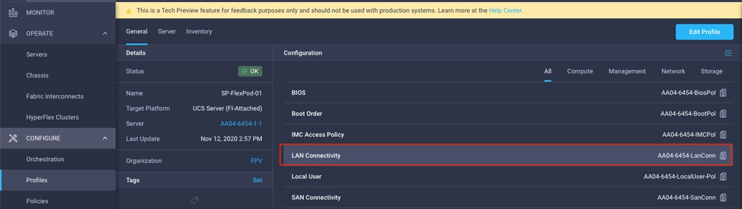
4. On the pane at the right, each NIC is listed along with the assigned MAC address. This information is useful for identifying the management (vSwitch0) vNICs when installing ESXi on the server and setting up the initial management access.
5. Click SAN Connectivity to gather information about the WWPN addresses assigned to vHBA-A and vHBA-B. This information is required to set up Cisco MDS zoning as well as to map boot LUNs to hosts on Pure Storage. This information can be added to Table 4 for quick reference.
Table 4. Server profile MAC and WWPN addresses
| Server profile |
Interface |
Address |
| SP-FlashStack-01 |
00-vSwitch0-A |
00:25:B5:A4:0A:01 |
|
|
01-vSwitch0-B |
00:25:B5:A4:0B:07 |
|
|
02-VDS0-A |
00:25:B5:A4:0A:06 |
|
|
03-VDS0-B |
00:25:B5:A4:0B:06 |
|
|
vHBA-A |
20:00:00:25:B5:A4:0A:00 |
|
|
vHBA-B |
20:00:00:25:B5:A4:0B:00 |
Note: Most policy changes prompt the user to redeploy the server profile. During the testing described in this document, because most of the features were in technical preview, the user was not always prompted to redeploy the server after changing some policies. As a best practice, server profile was redeployed after any policy changes, regardless of whether system prompted to do so.
The Cisco MDS configuration for zoning is no different than a typical Cisco MDS configuration in FlashStack. Please refer to Cisco MDS configuration information for zoning in the FlashStack deployment guide: https://www.cisco.com/c/en/us/td/docs/unified_computing/ucs/UCS_CVDs/flashstack_vsi_fc_vmware_vsphere_70.html#MDS9132TConfiguration
The Pure Storage FlashArray volume configuration can be performed using the configuration steps provided in the FlashStack deployment guide: https://www.cisco.com/c/en/us/td/docs/unified_computing/ucs/UCS_CVDs/flashstack_vsi_fc_vmware_vsphere_70.html#FlashArrayStorageDeployment
If you are using Pure Storage integration with Cisco Intersight, the volume creations workflows can be orchestrated using the Cisco Intersight orchestrator. The workflows available in Cisco Intersight orchestrator are listed in Table 3.
Note: Storage orchestration using the Cisco Intersight orchestrator is beyond the scope of this document and is therefore not covered here.
Deploy additional server profiles
When a server profile deployment is complete and verified to work correctly, you can deploy additional server profiles simply by cloning an existing server profile. An existing server profile can also be renamed before cloning (if required) by editing the profile and changing the name on the first screen.
Note: Customers should verify the various settings in the profile before creating additional clones and, preferably, test the server profile by installing and configuring an operating system.
To create additional server profiles by cloning, follow these steps:
1. Go to Profile and click the Options icon (…). Choose Clone.
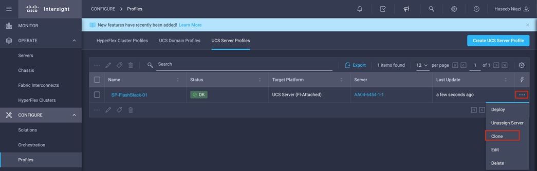
2. Under Server Assignment, keep the Assign Server selection and select an available server.
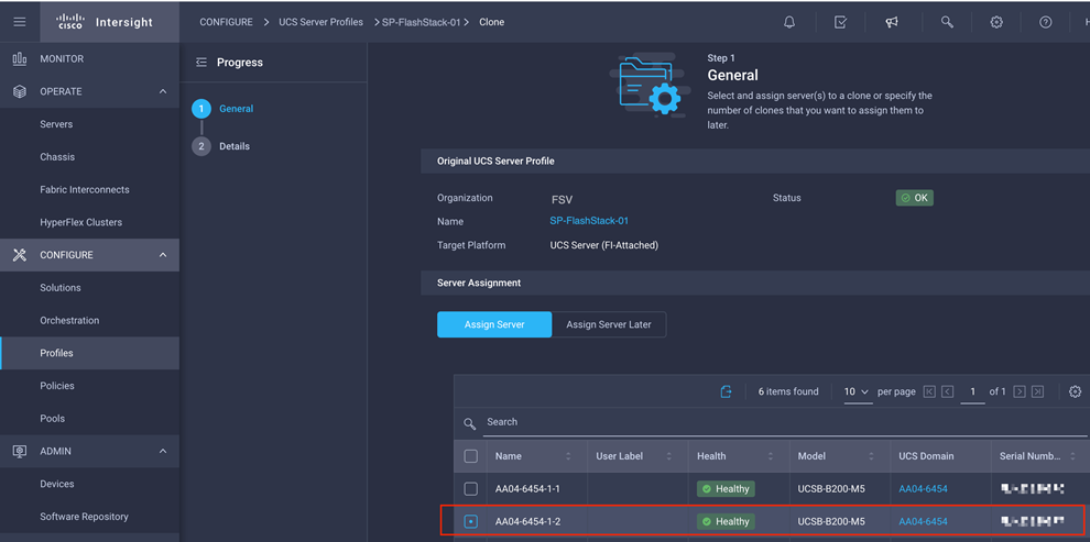
3. Click Next.
4. Provide the name of the new server profile by updating the clone name prefix and the clone name.
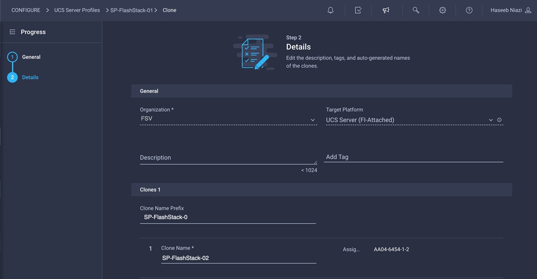
5. Click Clone & Deploy.
6. When the cloning process has been completed successfully, the new server profile is deployed.
7. Update the Cisco MDS switch and Pure Storage FlashArray with the appropriate WWPN information for zoning and for mapping boot LUNs to enable boot from SAN.
Install VMware ESXi on a server profile
When a server profile has been deployed successfully, install the operating system by following these steps:
1. Go to Servers and click the Options icon (…) next to the server and select Launch vKVM.
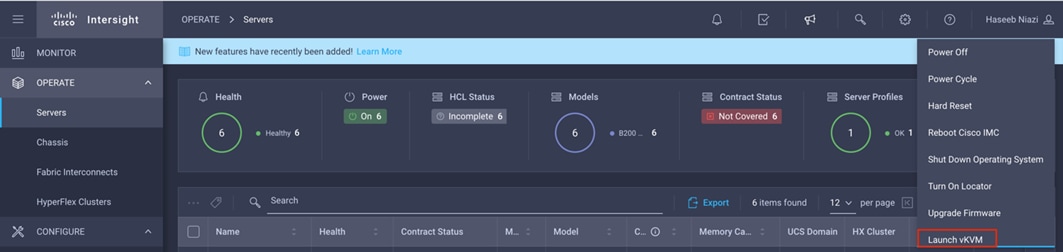
Note: Make sure that the virtual machine or host trying to access the KVM can route to the management IP address pool.
2. Log in using the username (for example, fsadmin) and password previously defined in the local user policy.
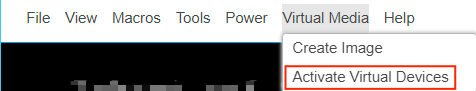
3. On this new KVM tab on the browser, click Virtual Media and choose Activate Virtual Devices.
4. Click Virtual Media again and choose Map CD/DVD.
5. Browse to the VMware ESXi ISO file and click Map Drive.
6. In the Cisco Intersight portal, follow these steps:
◦ Power-cycle the server by clicking the Options icon (…) next to the server and choosing Power Cycle.
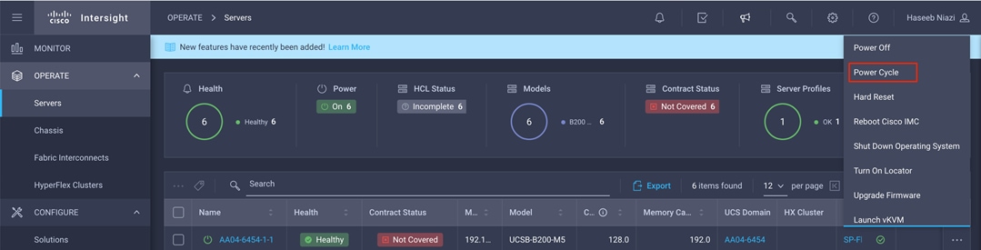
◦ Select Set One Time Boot Device and choose ISO (the label previously created for CD/DVD) from the drop-down menu.
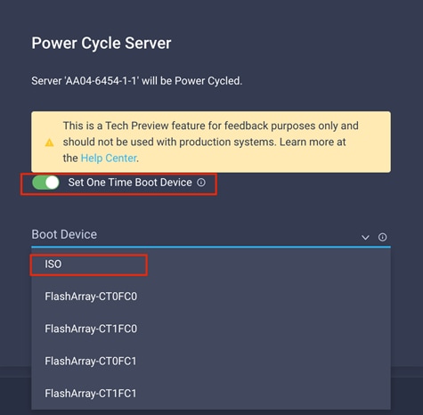
◦ Click Power Cycle.
7. On the KVM tab, in the KVM window, you should see the server being power-cycled. If the zoning and boot LUNs were configured correctly, you will see that the server has successfully discovered the boot LUN over all four paths.
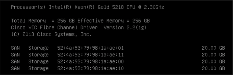
8. After ESXi has been installed and is loaded, navigate through the ESXi installer instructions. The installer should discover the Pure Storage boot LUN as an installation location.
9. Proceed with the ESXi installation. When the installation process is complete, unmap the installer using the Deactivate Virtual Devices menu option under Virtual Media and reboot the server.
Note: You can follow the Cisco Validated Design for FlashStack to set up VMware vCenter and other management tools.