-
Cisco Content Services Gateway Installation and Configuration Guide, Release 3.1(3)C5(5) --Last Updated January 26, 2007
-
About this Book
-
Overview
-
Installing the Hardware
-
Configuring the Content Services Gateway
-
Configuring Secure (Router) Mode, Redundancy, Fault Tolerance, and HSRP
-
Configuring RADIUS Support: Learning Who the Subscriber Is
-
Configuring Prepaid Support
-
PSD Configuration for the CSG
-
Command Reference
-
Protocol Compliance Statements for the CSG 3.1(3)C5(5)
-
Translated Safety Warnings
-
Table Of Contents
Configuring Secure (Router) Mode, Redundancy, Fault Tolerance, and HSRP
Configuring the Single Subnet (Bridge) Mode
Configuring the Secure (Router) Mode
Creating Fault-Tolerant HSRP Configurations
Configuring Connection Redundancy
Configuring Secure (Router) Mode, Redundancy, Fault Tolerance, and HSRP
This chapter describes how to configure some aspects of content switching that are necessary for the Content Services Gateway to function properly. This information is contained in the following sections:
•
Configuring the Single Subnet (Bridge) Mode
•
•
Configuring the Single Subnet (Bridge) Mode
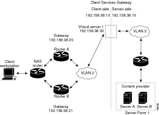
In a single subnet (bridge) mode configuration, the client-side and server-side VLANs are on the same subnets. Figure 4-1 illustrates a typical single subnet (bridge) mode configuration.
Figure 4-1 Single Subnet (Bridge) Mode Configuration
To configure single subnet (bridge) mode content switching, first configure a client-side VLAN and a server-side VLAN, using the following procedure:
Step 1
Router# vlan databaseEnters the VLAN configuration mode.
Step 2
Router(vlan)# vlan 2Configures a client-side VLAN.
Step 3
Router(vlan)# vlan 3Configures a server-side VLAN.
After you have configured a client-side VLAN and a server-side VLAN, assign the same IP address to the VLANs, using the following procedure:
After you have assigned the IP addresses, set the server's default routes to Server A's gateway (192.158.38.20) or Server B's gateway (192.158.38.21).
Configuring the Secure (Router) Mode
Because the client-side and server-side VLANs are on different subnets, you can configure the CSG to operate in a secure (router) mode. Figure 4-2 shows how to set up the secure (router) mode configuration.
Figure 4-2 Secure (Router) Mode Configuration
To configure content switching in secure (router) mode, first configure a client-side VLAN and a server-side VLAN, using the following procedure:
Step 1
Router# vlan databaseEnters the VLAN configuration mode.
Step 2
Router(vlan)# vlan 2Configures a client-side VLAN.
Step 3
Router(vlan)# vlan 3Configures a server-side VLAN.
After you have configured a client-side VLAN and a server-side VLAN, assign IP addresses to the VLANs, using the following procedure:
Configuring Fault Tolerance
This section describes a fault-tolerant (FT) configuration. In this configuration, two separate Catalyst 6000 series chassis each contain a CSG. The configuration can also apply to two separate Cisco 7600 series router chassis containing CSGs.
Note
In the secure (router) mode, the client-side and server-side VLANs provide the fault-tolerant (redundant) connection paths between the CSG and the routers on the client side and the servers on the server side. In a redundant configuration, two CSGs perform active and standby roles. Each CSG contains the same IP, virtual server, and server farm. From the client-side and server-side networks, each CSG is configured identically. The network sees the fault-tolerant configuration as a single CSG.
Note
If you have a pair of CSG cards and a pair of Content Services Module (CSM) cards in your network, do not configure both the CSG pair and the CSM pair to use the same FT VLAN. Use a different FT VLAN for each pair. If you configure the CSG pair and the CSM pair to use the same FT VLAN, then either service, the CSG or the CSM, is down in the standby mode.Configuring fault-tolerance requires the following:
•
•
•
•
•
•
The following command enables the calendar:
Cat6k-2# configure terminalCat6k-2(config)# clock timezone WORD offset from UTCCat6k-2(config)# clock calendar-valid•
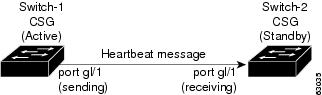
Figure 4-3 shows the QoS configuration topology.
Figure 4-3 QoS Configuration Topology
Without the secure (router) mode configuration shown in Figure 4-2, 802.1Q priority information is not preserved in packets traversing to the switch. Heartbeat messages sent from the active to the standby CSG must contain this priority information so that they are transmitted without delay. When an excessive delay occurs, an unnecessary takeover might occur.
You can overcome this limitation by configuring the sending port g1/1 to retain priority information upon transmission and the receiving port g1/1 to trust the class of service (CoS) (priority bits) for the incoming packets.
Configure the switch with the permit any any command to enable it to accept incoming packets with any MAC address from any MAC address.
To configure QoS for a fault-tolerant configuration, enter these commands:
Router(config)# mls qosRouter(config)# interface g1/1Router(config-if)# no shutdownRouter(config-if)# mls qos cos 7Router(config-if)# switchportRouter(config-if)# switchport access vlan 200Router(config-if)# switchport trunk encapsulation dot1qRouter(config-if)# switchport trunk allowed vlan 1,2,1002-1005Router(config-if)# switchport mode trunkTable 4-2 lists CSG fault-tolerant configuration requirements.
Table 4-2 The CSG Fault-Tolerant Configuration Requirements
VLAN name
X
VLAN address
X
Gateway1 address
X
Content name
X
Content IP address
X
Alias IP addresses
X
Redundancy group name
X
Redundancy VLAN ID
X
1 Server default gateways must point to the alias IP address.
Enter the replicate connection tcp command in content configuration mode to configure replication for the CSGs. (The default setting for the replicate command is disabled.)
If no router is present on the server-side VLAN, then each server's default route points to the alias IP address.
Figure 4-4 shows how to set up a secure (router) mode fault-tolerant configuration.
Figure 4-4 Fault-Tolerant Configuration
To configure the active (A) CSG for fault tolerance, use the following procedure:
To configure the standby (B) CSG for fault tolerance, perform this task (see Figure 4-4):
To configure fault tolerance in module CSG configuration mode, perform this task:
This example shows how to set fault tolerance for connection redundancy in module CSG configuration mode:
Router(config-module-csg)# ft group 90 vlan 111Router(config-csg-ft)# priority 10Router(config-csg-ft)# failover 3Router(config-cag-ft)# heartbeat-time 2Configuring HSRP
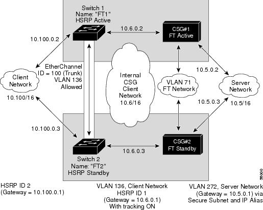
This section provides an overview of a Hot Standby Router Protocol (HSRP) configuration (see Figure 4-5) and describes how to configure the CSGs with HSRP and failover on the Catalyst 6000 series switches.
HSRP Configuration Overview
Figure 4-5 shows that two Catalyst 6000 series switches, Switch 1 and Switch 2, are configured to route from a client-side network (10.100/16) to an internal CSG client network (10.6/16, VLAN 136) through an HSRP gateway (10.100.0.1). The configuration shows the following:
•
•
Note
In the example configuration, two CSGs (one in Switch 1 and one in Switch 2) are configured to forward traffic between a client-side and a server-side VLAN:
•
•
The actual servers on the server network point to the CSG server network through an aliased gateway (10.5.0.1), allowing the servers to run a secure subnet.
In the example configuration, an EtherChannel is set up with trunking enabled, allowing traffic on the internal CSG client network to travel between the two Catalyst 6000 series switches.
Note
Figure 4-5 HSRP Configuration
Creating the HSRP Gateway
The following procedure describes how to create an HSRP gateway for the client-side network. The gateway is HSRP ID 2 for the client-side network. In this example, HSRP is set on Fast Ethernet ports 3/6.
To create an HSRP gateway, follow these steps:
Step 1
Router(config)# interface FastEthernet3/6Router(config)# ip address 10.100.0.2 255.255.0.0Router(config)# standby 2 priority 110Router(config)# standby 2 ip 10.100.0.1Step 2
Router(config)#interface FastEthernet3/6Router(config)# ip address 10.100.0.3 255.255.0.0Router(config)# standby 2 priority 100Router(config)# standby 2 ip 10.100.0.1Creating Fault-Tolerant HSRP Configurations
This section describes how to create a fault-tolerant HSRP secure mode configuration. To create a nonsecure mode configuration, enter the commands described with these exceptions:
•
•
To create fault-tolerant HSRP configurations, follow these steps.
Step 1
Router(config)# module csg 5Router(config-module-csg)# vlan 136 clientRouter(config-csg-vlan-client)# ip address 10.6.0.245 255.255.0.0Router(config-csg-vlan-client)# gateway 10.6.0.1Router(config-csg-vlan-client)# exitRouter(config-module-csg)# vlan 272 serverRouter(config-csg-vlan-server)# ip address 10.5.0.2 255.255.0.0Router(config-csg-vlan-server)# alias 10.5.0.1 255.255.0.0Router(config-csg-vlan-server)# exitRouter(config-module-csg)# vlan 71 ftRouter(config-module-csg)# ft group 88 vlan 71Router(config-csg-ft)# priority 30Router(config-csg-ft)# exitRouter(config-module-csg)# interface Vlan136ip address 10.6.0.2 255.255.0.0standby 1 priority 100standby 1 ip 10.6.0.1standby 1 track Fa3/6 10Step 2
Router(config)# module csg 6Router(config-module-csg)# vlan 136 clientRouter(config-csg-vlan-client)# ip address 10.6.0.246 255.255.0.0Router(config-csg-vlan-client)# gateway 10.6.0.1Router(config-csg-vlan-client)# exitRouter(config-module-csg)# vlan 272 serverRouter(config-csg-vlan-server)# ip address 10.5.0.3 255.255.0.0Router(config-csg-vlan-server)# alias 10.5.0.1 255.255.0.0Router(config-csg-vlan-server)# exitRouter(config-module-csg)# vlan 71 ftRouter(config-module-csg)# ft group 88 vlan 71Router(config-csg-ft)# priority 20Router(config-csg-ft)# exitRouter(config-module-csg)# interface Vlan136ip address 10.6.0.3 255.255.0.0standby 1 priority 100standby 1 ip 10.6.0.1standby 1 track Fa3/6 10Step 3
Router(console)# interface Port-channel100Router(console)# switchportRouter(console)# switchport trunk encapsulation dot1qRouter(console)# switchport trunk allowed vlan 136
Note
Step 4
Router(console)# switchport trunk remove vlan 71Router(console)# switchport trunk remove vlan 272Step 5
Router(console)# interface FastEthernet3/25Router(console)# switchportRouter(console)# channel-group 100 mode on
Configuring Connection Redundancy
Connection redundancy prevents open connections from hanging when the active CSG fails and the standby CSG becomes active. With connection redundancy, the active CSG replicates forwarding information to the standby CSG for each connection that is to remain open when the active CSG fails over to the standby CSG.
The CSG also supports stateful redundancy for TCP connections. That is, the session continues to be billed even when the primary CSG fails and the backup CSG takes over.
Stateful redundancy is not supported for RTSP connections. For all other connections, a new session is created when the backup CSG becomes active.
To configure connection redundancy, perform this task:
This example shows how to configure connection redundancy:
Router(config)# ip csg content CISCORouter(config-csg-content)# ip 10.10.10.10 tcp telnetRouter(config-csg-content)# replicate connection tcpRouter(config-csg-content)# inservice