Feedback Feedback
|
Table Of Contents
Cisco Unified CallManager 4.0 Integration Guide for Cisco Unity 4.0
Task List to Create the Integration
Task List to Make Changes to an Integration
Task List to Change the Number of Voice Messaging Ports
Task List to Delete an Existing Integration
Integrations with Multiple Phone Systems
Planning How the Voice Messaging Ports Will Be Used by Cisco Unity
Preparing for Programming the Phone System
Programming the Cisco Unified CallManager Phone System
For a Cisco Unity Server Without Failover or for a Cisco Unity Primary Server
For a Cisco Unity Secondary Server
Setting Up the Gateways That Service Cisco Unity
Creating a New Integration with the Cisco Unified CallManager Phone System (SCCP)
Integrating a Secondary Server for Cisco Unity Failover
Setting Up the Secondary Server for Failover
Changing the Settings for an Existing Integration
Changing the Number of Voice Messaging Ports
Deleting an Existing Integration
Appendix: Using Alternate Extensions and MWIsSetting Up Alternate Extensions
Setting Up Alternate MWIs for Extensions on the Same Phone System
MWIs for Extensions on a Non-Integrated Phone System
Setting Up MWIs for Extensions on a Non-Integrated Phone System
Appendix: Documentation and Technical AssistanceCisco Product Security Overview
Reporting Security Problems in Cisco Products
Obtaining Technical Assistance
Cisco Technical Support & Documentation Website
Definitions of Service Request Severity
Obtaining Additional Publications and Information
Cisco Unified CallManager 4.0 Integration Guide for Cisco Unity 4.0
Revised March 31, 2006
This document provides instructions for integrating the phone system with Cisco Unity.
Integration Tasks
Before doing the following tasks to integrate Cisco Unity with the Cisco Unified CallManager phone system, confirm that the Cisco Unity server is ready for the integration by completing the applicable tasks in the applicable Cisco Unity installation guide.
The following task lists describe the process for creating, changing, and deleting integrations.
Task List to Create the Integration
Use the following task list to set up a new integration with the Cisco Unified CallManager phone system. If you are installing a new Cisco Unity server by using the applicable Cisco Unity installation guide, you may have already completed some of the following tasks.
1.
Review the system and equipment requirements to confirm that all phone system and Cisco Unity server requirements have been met. See the "Requirements" section.
2.
3.
•
•
•
4.
5.
6.
7.
Task List to Make Changes to an Integration
Use the following task list to make changes to an integration after it has been created.
1.
2.
Task List to Change the Number of Voice Messaging Ports
Use the following task list to change the number of voice messaging ports for an integration after it has been created.
1.
2.
3.
Task List to Delete an Existing Integration
Use the following task list to remove an existing integration.
1.
2.
Requirements
The Cisco Unified CallManager integration supports configurations of the following components:
Phone System
•
•
•
•
Cisco Unity Server
•
•
•
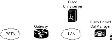
Integration Description
The Cisco Unified CallManager integration uses the LAN to connect Cisco Unity and the phone system. The gateway provides connections to the PSTN. Figure 1 shows the connections.
Figure 1 Connections Between the Phone System and Cisco Unity
Call Information
The phone system sends the following information with forwarded calls:
•
•
•
Cisco Unity uses this information to answer the call appropriately. For example, a call forwarded to Cisco Unity is answered with the personal greeting of the subscriber. If the phone system routes the call to Cisco Unity without this information, Cisco Unity answers with the opening greeting.
Integration Functionality
The Cisco Unified CallManager integration with Cisco Unity provides the following features:
•
•
•
•
•
•
The functionality of this integration may be affected by the issues described below.
Use of Cisco Unified Survivable Remote Site Telephony (SRST) Router
When a Cisco Unified Survivable Remote Site Telephony (SRST) router is part of the network and the Cisco Unified SRST router takes over call processing functions from Cisco Unified CallManager (for example, because the WAN link is down), phones at a branch office can continue to function. In this situation, however, the integration features have the following limitations:
•
•
•
•
•
•
•
When the Cisco Unified SRST router uses PRI/BRI connections, the caller ID for calls from a branch office to Cisco Unity may be the full number (exchange plus extension) provided by the PSTN and therefore may not match the extension of the Cisco Unity subscriber. If this is the case, you can let Cisco Unity recognize the caller ID by using alternate extensions (for instructions, see the "Appendix: Using Alternate Extensions and MWIs" section) or by using extension remapping (for instructions, refer to the "Remapping Extension Numbers" section of the "System Settings" chapter in the applicable Cisco Unity System Administration Guide (release 4.0(3) or later), available at http://www.cisco.com/en/US/products/sw/voicesw/ps2237/prod_maintenance_guides_list.html.
Redirected Dialed Number Information Service (RDNIS) needs to be supported when using SRST.
For information on setting up Cisco Unified SRST routers, refer to the "Integrating Voice Mail with Cisco Unified SRST" section of the Cisco Unified SRST System Administrator Guide at http://www.cisco.com/univercd/cc/td/doc/product/software/ios122/122newft/122limit/122z/122zj15/index.htm.
Impact of Non-Delivery of RDNIS on Voice Mail Calls Routed via AAR
RDNIS needs to be supported when using Automated Alternate Routing (AAR).
AAR can route calls over the PSTN when the WAN is oversubscribed. However, when calls are rerouted over the PSTN, RDNIS can be affected. Incorrect RDNIS information can affect voice mail calls that are rerouted over the PSTN by AAR when Cisco Unity is remote from its messaging clients. If the RDNIS information is not correct, the call will not reach the voice mail box of the dialed user but will instead receive the automated attendant prompt, and the caller might be asked to reenter the extension number of the party they wish to reach. This behavior is primarily an issue when the telephone carrier is unable to ensure RDNIS across the network. There are numerous reasons why the carrier might not be able to ensure that RDNIS is properly sent. Check with your carrier to determine whether it provides guaranteed RDNIS delivery end-to-end for your circuits. The alternative to using AAR for oversubscribed WANs is simply to let callers hear reorder tone in an oversubscribed condition.
Integrations with Multiple Phone Systems
Depending on the version, Cisco Unity can be integrated with two or more phone systems:
•
•
Planning How the Voice Messaging Ports Will Be Used by Cisco Unity
Before programming the phone system, you need to plan how the voice messaging ports will be used by Cisco Unity. The following considerations will affect the programming for the phone system (for example, setting up the hunt group or call forwarding for the voice messaging ports):
•
•
•
•
The following table describes the voice messaging port settings in Cisco Unity that can be set in UTIM, and that are displayed as read-only text on the System > Ports page of the Cisco Unity Administrator.
The Number of Voice Messaging Ports to Install
The number of voice messaging ports to install depends on numerous factors, including:
•
•
•
•
•
•
•
•
•
It is best to install only the number of voice messaging ports that are needed so that system resources are not allocated to unused ports.
The Number of Voice Messaging Ports That Will Answer Calls
The calls that the voice messaging ports answer can be incoming calls from unidentified callers or from subscribers. Typically, the voice messaging ports that answer calls are the busiest.
You can set voice messaging ports to both answer calls and to dial out (for example, to send message notifications). However, when the voice messaging ports perform more than one function and are very active (for example, answering many calls), the other functions may be delayed until the voice messaging port is free (for example, message notifications cannot be sent until there are fewer calls to answer). For best performance, dedicate certain voice messaging ports for only answering incoming calls, and dedicate other ports for only dialing out. Separating these port functions eliminates the possibility of a collision, in which an incoming call arrives on a port at the same time that Cisco Unity takes the port off-hook to dial out.
The Number of Voice Messaging Ports That Will Only Dial Out, and Not Answer Calls
Ports that will only dial out and will not answer calls can do one or more of the following:
•
•
•
•
Typically, these voice messaging ports are the least busy ports.
Caution
The Number of Voice Messaging Ports That Will Be Dedicated to Activating MWIs on Other Cisco Unified CallManager Clusters
If Cisco Unity services multiple clusters of Cisco Unified CallManager, there must be at least one voice messaging port per cluster dedicated for turning MWIs on and off for each cluster. For example, if the system has four clusters, at least four ports on Cisco Unity must be dedicated to activating MWIs, one port for each cluster.
Preparing for Programming the Phone System
Record your decisions about the voice messaging ports to guide you in programming the phone system.
Programming the Cisco Unified CallManager Phone System
After Cisco Unified CallManager software is installed, do the procedures in the applicable section to program Cisco Unified CallManager to work with Cisco Unity:
•
•
•
For a Cisco Unity Server Without Failover or for a Cisco Unity Primary Server
Do the following procedures in the order given.
To Add Partitions and a Calling Search Space to Contain the Voice Mail Ports
Step 1
Step 2
Step 3
Step 4
Step 5
Step 6
Step 7
Step 8
Step 9
Step 10
Step 11
Step 12
The name of the partition appears in the Selected Partitions field.
Step 13
Step 14
Step 15
Step 16
Step 17
Caution
Step 18
Step 19
To Add a Device Pool for the Voice Mail Ports
Step 1
Step 2
Step 3
Step 4
To Add Voice Mail Ports to Cisco Unified CallManager
Add a voice mail port to Cisco Unified CallManager for each port that you are connecting to Cisco Unity (either for a Cisco Unity server without failover or for a Cisco Unity primary server).
Step 1
Step 2
Step 3
Caution
Step 4
Step 5
If you will integrate Cisco Unity with multiple clusters of Cisco Unified CallManager, the number you enter here cannot bring the total number of ports on all clusters integrated with Cisco Unity to more than the number of ports enabled by the Cisco Unity license.
Step 6
Step 7
Step 8
Table 4 Settings for the Voice Mail Directory Numbers Page
Beginning Directory Number
Enter the extension number of the first voice mail port.
Partition
Click the name of the partition that you set up for all voice mail port directory numbers. For example, click "VMRestrictedPT."
Calling Search Space
Click the name of a calling search space that you set up to contain the partition with all voice mail port directory numbers, as set in Step 9 of the "To Add Partitions and a Calling Search Space to Contain the Voice Mail Ports" procedure. For example, click "VMRestrictedCSS."
Because this calling search space is not used by subscriber phones, subscribers are not able to dial the voice mail ports. However, subscribers can dial the voice mail pilot number.
Display
Accept the default of Voicemail. (This text appears on the phone when the pilot number is dialed.)
Caution
AAR Group
Click the automated alternate routing (AAR) group for the voice mail ports. The AAR group provides the prefix digits that are used to route calls that are otherwise blocked due to insufficient bandwidth. If you click None, no rerouting of blocked calls will be attempted.
External Number Mask
Leave this field blank, or specify the mask used to format caller ID information for external (outbound) calls. The mask can contain up to 50 characters. Enter the literal digits that you want to appear in the caller ID information, and enter X for each digit in the directory number of the device.
Step 9
Step 10
Step 11
If the settings are not correct, click Back and enter the correct settings.
To Add Voice Mail Ports to Line Groups
Step 1
You can also reach the line group pages by clicking Route Plan > Route/Hunt > Line Group in the Cisco Unified CallManager Administration.
Step 2
This line group will contain directory numbers for voice mail ports that will answer calls. Directory numbers for voice mail ports that will only dial out (for example, to set MWIs) must not be included in this line group.
Step 3
Step 4
Step 5
Step 6
Caution
Step 7
Caution
Step 8
Step 9
Otherwise, skip the remaining steps in this procedure and continue on to the "To Add the Line Group to a Route/Hunt List" procedure.
Step 10
This line group will contain directory numbers for voice mail ports that will only dial out. Directory numbers for voice mail ports that answer calls must not be included in this line group.
Step 11
Step 12
Step 13
Step 14
Caution
Step 15
Caution
Step 16
To Add the Line Group to a Route/Hunt List
Step 1
Step 2
Step 3
Step 4
Step 5
Step 6
Step 7
Step 8
Step 9
Step 10
Step 11
To Add the Route/Hunt List to a Hunt Pilot Number
Step 1
Step 2
Step 3
Table 8 Settings for Route Pattern/Hunt Pilot Configuration Page
Route Pattern/Hunt Pilot
Enter the hunt pilot number for the voice mail ports. The hunt pilot number must be different from the extension numbers of the voice mail ports.
The hunt pilot number is the extension number that subscribers enter to listen to their voice messages.
Partition
Click the name of the partition that you set up for the voice mail pilot number. For example, click "VMPilotNumberPT."
Description
Enter Cisco Unity Hunt Pilot or another description.
Numbering Plan
Accept the default setting, or click the numbering plan that you have set up for your system.
Route Filter
Click None, or click the name of the route filter that you set up for your system.
MLPP Precedence
Accept the default setting, or click another setting.
Gateway or Route/Hunt List
Click the route/hunt list of voice mail ports that answer calls, which you set up in the "To Add the Line Group to a Route/Hunt List" procedure.
Provide Outside Dial Tone
Uncheck the check box.
Step 4
To Specify MWI Directory Numbers
Step 1
Step 2
Step 3
Step 4
Step 5
Step 6
Step 7
To Add a Voice Mail Pilot Number for the Voice Mail Ports
The voice mail pilot number is the extension that you dial to listen to your voice messages. Your Cisco IP phone automatically dials the voice mail pilot number when you press the Messages button.
Step 1
Step 2
Step 3
Step 4
To Set Up the Voice Mail Profile
Step 1
Step 2
Step 3
Step 4
To Set Up the Voice Mail Server Service Parameters
Step 1
Step 2
Step 3
Step 4
Step 5
When this parameter is set to True, Cisco Unified CallManager uses any configured translation patterns to convert voice mail extensions into directory numbers when turning on or off an MWI.
Step 6
Step 7
Step 8
If your Cisco Unity system is not configured for failover, skip to the "Setting Up the Gateways That Service Cisco Unity" section. If your system uses failover, continue on to the "For a Cisco Unity Secondary Server" section.
Note
For a Cisco Unity Secondary Server
When you program Cisco Unified CallManager for the secondary Cisco Unity server, do the following procedures in the order given.
To Add Voice Mail Ports to Cisco Unified CallManager (Secondary Cisco Unity Server)
Add a voice mail port to Cisco Unified CallManager for each port that you are connecting to the secondary Cisco Unity server.
Step 1
Step 2
Step 3
Caution
Step 4
Step 5
If you will integrate Cisco Unity with multiple clusters of Cisco Unified CallManager, the number you enter here cannot bring the total number of ports on all clusters integrated with Cisco Unity to more than the number of ports enabled by the Cisco Unity license.
Step 6
Step 7
Step 8
Table 14 Settings for the Cisco Voice Mail Directory Numbers Page
Beginning Directory Number
Enter the extension number of the first voice mail port that will connect to the secondary Cisco Unity server.
Partition
Click the name of the partition that you set up for all voice mail port directory numbers. For example, click "VMRestrictedPT."
Calling Search Space
Click the name of a calling search space that you set up to contain the partition with all voice mail port directory numbers, as set in Step 9 of the "To Add Partitions and a Calling Search Space to Contain the Voice Mail Ports" procedure. For example, click "VMRestrictedCSS."
Because this calling search space is not used by subscriber phones, subscribers are not able to dial the voice mail ports. However, subscribers can dial the voice mail pilot number.
Display
Accept the default of Voicemail.
This text appears on the phone when the pilot number is dialed.
AAR Group
Click the automated alternate routing (AAR) group for the voice mail ports. The AAR group provides the prefix digits that are used to route calls that are otherwise blocked due to insufficient bandwidth. If you click None, no rerouting of blocked calls will be attempted.
External Number Mask
Leave this field blank, or specify the mask used to format caller ID information for external (outbound) calls. The mask can contain up to 50 characters. Enter the literal digits that you want to appear in the caller ID information, and enter X for each digit in the directory number of the device.
Step 9
Step 10
Step 11
If the settings are not correct, click Back and enter the correct settings.
To Add Voice Mail Ports to Line Groups (Secondary Cisco Unity Server)
Step 1
You can also reach the line group pages by clicking Route Plan > Route/Hunt > Line Group in the Cisco Unified CallManager Administration.
Step 2
This line group will contain directory numbers for voice mail ports that will answer calls. Directory numbers for voice mail ports that will only dial out (for example, to set MWIs) must not be included in this line group.
Step 3
Step 4
Step 5
Step 6
Caution
Step 7
Caution
Step 8
Step 9
Otherwise, skip the remaining steps in this procedure and continue on to the "To Add the Line Group to a Route/Hunt List (Secondary Cisco Unity Server)" procedure.
Step 10
This line group will contain directory numbers for voice mail ports that will only dial out. Directory numbers for voice mail ports that answer calls must not be included in this line group.
Step 11
Step 12
Step 13
Step 14
Caution
Step 15
Caution
Step 16
To Add the Line Group to a Route/Hunt List (Secondary Cisco Unity Server)
Step 1
Step 2
Otherwise, continue with Step 3.
Step 3
Step 4
Step 5
Step 6
Step 7
Step 8
Step 9
Setting Up the Gateways That Service Cisco Unity
In certain situations, DTMF digits are not recognized when processed through VoIP dial-peer gateways. To avoid this problem, certain gateways must be configured to enable DTMF relay. The DTMF relay feature is available in Cisco IOS software version 12.0(5) and later.
Cisco IOS software-based gateways that use H.245 out-of-band signaling must be configured to enable DTMF relay.
The Catalyst 6000 T1/PRI and FXS gateways enable DTMF relay by default and do not need additional configuration to enable this feature.
To Enable DTMF Relay
Step 1
dtmf-relay h245-alphanumericStep 2
Step 3
For information about the supported gateways for the Cisco Unity Bridge or AMIS, refer to the following documents:
•
•
Creating a New Integration with the Cisco Unified CallManager Phone System (SCCP)
After ensuring that the Cisco Unified CallManager phone system and the Cisco Unity server are ready for the integration, do the following procedures to set up the integration and to enter the port settings.
Note
To Create an Integration
Step 1
Step 2
Step 3
Step 4
•
•
Step 5
Step 6
Step 7
You can click Ping Server to confirm that the IP address is correct.
Step 8
The IP addresses of the subscriber Cisco Unified CallManager servers must appear in descending order, so that the subscriber Cisco Unified CallManager server at the top of the list is the first to take over call processing functions during failover, and the publisher Cisco Unified CallManager server is the last.
You can click Ping Servers to confirm that the IP addresses are correct.
Step 9
Step 10
Step 11
Step 12
You can click Verify to confirm that the CallManager device name prefix is correct.
Step 13
Step 14
If no subscribers appear in the list, click Next and continue to Step 15.
Otherwise, select the subscribers that you want to assign to this phone system integration and click Next. You can use the following selection controls for selecting subscribers.
Step 15
If no call handlers appear in the list, click Next and continue to Step 16.
Otherwise, select the call handlers that you want to assign to this phone system integration and click Next. You can use the following selection controls for selecting call handlers.
Step 16
Step 17
Alternatively, you can restart the Cisco Unity services in UTIM on the Tools menu by clicking Restart Cisco Unity.
To Enter the Voice Messaging Port Settings for the Integration
Step 1
Step 2
Step 3
Step 4
Step 5
For the voice messaging ports assigned to a given Cisco Unified CallManager cluster, to get the best performance use the first voice messaging ports for incoming calls and the last ports to dial out. This helps minimize the possibility of a collision, in which an incoming call arrives on a port at the same time that Cisco Unity takes the port off-hook to dial out. Set the ports assigned to each Cisco Unified CallManager cluster in this manner.
Caution
Step 6
Step 7
Step 8
If Cisco Unity integrates with multiple clusters of Cisco Unified CallManager, continue to the next procedure.
To Create an Integration with a Second Cluster of Cisco Unified CallManager
If Cisco Unity integrates with only one cluster of Cisco Unified CallManager, skip this procedure.
Step 1
Step 2
Step 3
Step 4
Step 5
Step 6
Step 7
If there are additional Cisco Unified CallManager servers in this cluster, click Add. The Servers dialog box appears.
Step 8
Step 9
Step 10
Step 11
Step 12
Step 13
Step 14
Step 15
This number cannot be more than the number of ports set up on the Cisco Unified CallManager cluster. This number cannot bring the total number of port installed on the Cisco Unity server to more than the number of ports enabled by the Cisco Unity license.
Step 16
Caution
Step 17
Step 18
Step 19
Alternatively, you can restart the Cisco Unity services in UTIM on the Tools menu by clicking Restart Cisco Unity.
Step 20
Step 21
Testing the Integration
To test whether Cisco Unity and the phone system are integrated correctly, do the following procedures in the order listed.
If any of the steps indicate a failure, refer to the following documentation as applicable:
•
•
•
To Set Up the Test Configuration
Step 1
Step 2
Caution
Step 3
If your message store is Microsoft Exchange, do the following:
a.
b.
c.
d.
e.
If your message store is IBM Lotus Domino, do the following:
a.
b.
c.
d.
If the address book that you want to use is not listed, go to the System > Configuration > Subscriber Address Books page and add a different address book.
e.
f.
g.
h.
i.
j.
Step 4
Step 5
Step 6
Step 7
For more information on transfer settings, refer to the "Subscriber Template Call Transfer Settings" section in the Cisco Unity Administrator Help.
Step 8
Step 9
Step 10
Step 11
Step 12
Step 13
Step 14
Step 15
•
•
•
To Test an External Call with Release Transfer
Step 1
Step 2
Step 3
Step 4
Step 5
Step 6
Step 7
Step 8
Step 9
Step 10
To Test Listening to Messages
Step 1
Step 2
Step 3
Step 4
Step 5
Step 6
Step 7
Step 8
To Set Up Supervised Transfer on Cisco Unity
Step 1
If the name of the test subscriber is not displayed, click the Find icon (the magnifying glass) in the title bar, then click Find, and select the name of the test subscriber in the list that appears.
For more information on transfer settings, refer to the "Subscriber Template Call Transfer Settings" section in the Cisco Unity Administrator Help.
Step 2
Step 3
Step 4
To Test Supervised Transfer
Step 1
Step 2
Step 3
Step 4
Step 5
Step 6
Step 7
Step 8
To Delete the Test Subscriber
Step 1
If the name of the test subscriber is not displayed, click the Find icon (the magnifying glass) in the title bar, then click Find, and select the name of the test subscriber in the list that appears.
Step 2
Step 3
Integrating a Secondary Server for Cisco Unity Failover
The Cisco Unity failover feature enables a secondary server to provide voice messaging services when the primary server becomes inactive. For information on installing a secondary server for failover, refer to the applicable Cisco Unity installation guide, available at http://www.cisco.com/en/US/products/sw/voicesw/ps2237/prod_installation_guides_list.html.
For information on failover, refer to the Cisco Unity Failover Configuration and Administration Guide. The Domino version of the guide is available at http://www.cisco.com/univercd/cc/td/doc/product/voice/c_unity/fail/fail401/dom/index.htm. The Exchange version of the guide is available at http://www.cisco.com/univercd/cc/td/doc/product/voice/c_unity/fail/fail401/ex/index.htm.
Requirements
The following components are required to integrate a secondary server:
•
•
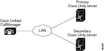
Integration Description
The phone system communicates with both the primary and secondary servers through the LAN. Figure 2 shows the required connections.
Figure 2 Connections Between Cisco CallManager and the Cisco Unity Servers
The primary and secondary servers act in the following manner:
•
•
•
Setting Up the Secondary Server for Failover
Before proceeding, confirm that Cisco Unified CallManager is configured as described in the "Programming the Cisco Unified CallManager Phone System" section earlier in this integration guide. In particular, confirm that the name of the voice mail server and voice mail ports that serve the secondary server are different from the name of the voice mail server and voice mail ports that serve the primary server.
Do the following procedure to integrate the secondary server.
To Set Up the Secondary Server for Failover
Step 1
Step 2
Step 3
Step 4
The CallManager Device Name Prefix setting for the secondary server must be different from the CallManager Device Name Prefix setting for the primary server. Otherwise, the secondary server cannot function correctly.
Note
Step 5
Note
Step 6
Step 7
Step 8
For Cisco Unity 4.2 and later, do the following substeps.
a.
b.
c.
If the integration IDs of the phone system on the primary and secondary servers are different, on the secondary server, click Modify Integration ID.
d.
e.
f.
g.
h.
Step 9
Step 10
Step 11
Step 12
Step 13
Changing the Settings for an Existing Integration
After the integration is set up, if you want to change any of its settings (for example, to change the MWI settings), do the following procedure.
If you want to change the number of voice messaging ports, see the Changing the Number of Voice Messaging Ports.
To Change the Settings for an Integration
Step 1
Step 2
Step 3
Step 4
Step 5
Step 6
Caution
Step 7
Step 8
Changing the Number of Voice Messaging Ports
To change the number of voice messaging ports after you have finished installing and setting up Cisco Unified CallManager, do the following procedures.
To Change the Number of Voice Messaging Ports in the Cisco Unified CallManager Administration
Step 1
For information on adding voice messaging ports, see the "To Add Voice Mail Ports to Cisco Unified CallManager" procedure. For information on removing voice mail ports, refer to the Cisco Unified CallManager Administrator Help.
Step 2
To Update Cisco Unity for Additional Voice Messaging Ports
Step 1
Step 2
Step 3
Step 4
Note
Step 5
Deleting an Existing Integration
If you want to delete an existing integration (for example, you have replaced the phone system with which Cisco Unity originally integrated), do the following procedure.
To Delete an Existing Integration
Step 1
Step 2
Step 3
Step 4
Step 5
Step 6
Alternatively, you can restart the Cisco Unity services in UTIM on the Tools menu by clicking Restart Cisco Unity.
Step 7
Appendix: Using Alternate Extensions and MWIs
Alternate Extensions
In addition to the "primary" extension that you specify for subscribers, you can assign subscribers up to nine alternate extensions. (The primary extension is the one that you assign to each subscriber when you create his or her subscriber account; it is listed on the Subscribers > Subscribers > Profile page.)
Reasons to Use Alternate Extensions
There are several reasons that you may want to specify alternate extensions for subscribers. For example, if you have more than one Cisco Unity server that accesses a single, corporate-wide directory, you may want to use alternate extensions to simplify addressing messages to subscribers at the different locations. With alternate extensions, the number that a subscriber uses when addressing a message to someone at another location can be the same number that the subscriber dials when calling. You may also want to use alternate extensions to:
•
•
Tip
•
How Alternate Extensions Work
Before you set up alternate extensions, review the following list for information on how alternate extensions work:
•
You can use the Advanced Settings tool in Tools Depot to specify a minimum extension length for the extensions entered in the Cisco Unity Administrator and the Cisco Unity Assistant. Refer to the Advanced Settings Tool Help for details on using the settings. Respectively, the settings are Administration—Set the Minimum Length for Locations, and Administration—Set the Minimum Length for Subscriber-Defined Alternate Extensions.
•
•
•
•
Setting Up Alternate Extensions
Do the applicable procedure to add, modify, or delete alternate extensions:
•
•
To Add Administrator-Defined Alternate Extensions
Step 1
Step 2
•
•
•
•
•
Step 3
Step 4
To Modify or Delete Alternate Extension(s)
Step 1
Step 2
•
•
•
Step 3
Step 4
Note
Alternate MWIs
You can set up Cisco Unity to activate alternate MWIs when you want a new message for a subscriber to activate the MWIs at up to 10 extensions. For example, a message left at extension 1001 can activate the MWIs on extensions 1001 and 1002.
Cisco Unity uses MWIs to alert the subscriber to new voice messages. MWIs are not used to indicate new e-mail, fax, or return receipt messages.
In Cisco Unified CallManager integrations, you can also use the alternate MWI feature to activate MWIs on a non-integrated phone system that can send and receive information from Cisco Unity over an RS-232 serial cable.
This section contains the following information:
•
•
•
Setting Up Alternate MWIs for Extensions on the Same Phone System
Cisco Unity can activate alternate MWIs for extensions on the same phone system. Note that depending on the phones and phone systems, some additional phone system programming may be necessary. Refer to the installation guide for the phone system.
To enable alternate MWIs for extensions on the same phone system, do the following procedure for each subscriber who needs alternate MWIs.
To Set Up Alternate MWIs for Extensions on the Same Phone System
Step 1
Step 2
Step 3
Step 4
•
•
•
Step 5
Step 6
Note
To change or delete alternate MWIs for extensions, do the following procedure.
To Modify or Delete Alternate MWIs
Step 1
Step 2
•
•
Step 3
Step 4
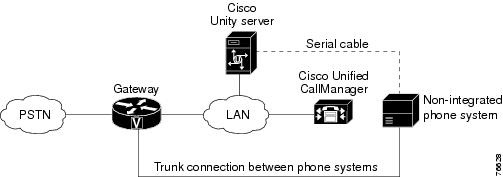
MWIs for Extensions on a Non-Integrated Phone System
Cisco Unity can activate MWIs on a phone system that is not integrated with Cisco Unity and that is not part of a two phone system integration (referred to here as a non-integrated phone system). MWI activation requests are sent through an RS-232 serial cable.
For this method, you must set up:
•
•
•
•
•
Figure 3 shows the connections via a serial cable between a Cisco Unified CallManager integration and a non-integrated phone system.
Figure 3 Connection for Sending Alternate MWIs via a Serial Cable to a Non-Integrated Phone System from a Cisco CallManager Integration
Calls to subscribers that come from the non-integrated phone system are routed through the gateway to Cisco CallManager.
Setting Up MWIs for Extensions on a Non-Integrated Phone System
To set up MWIs for extensions on a non-integrated phone system, do the following applicable procedures.
To Set Up MWIs on a Non-Integrated Phone System
Step 1
Step 2
•
•
•
•
Step 3
To Revise the Switch.ini File
Step 1
Step 2
Step 3
Step 4
Step 5
Step 6
Step 7
Step 8
[Alternate MWI]Active=YesDigit=ZMWIType=SerialSerialConfiguration=<if applicable, the type of serialconfiguration for the connection>
Step 9
Do the following procedure if the serial configuration used by the non-integrated phone system is different from the default serial configuration that Cisco Unity uses.
To Revise the Cisco Unity Serial Configuration File
Step 1
Step 2
Step 3
•
•
•
•
Step 4
Step 5
Appendix: Documentation and Technical Assistance
Conventions
The Cisco Unified CallManager 4.0 Integration Guide for Cisco Unity 4.0 uses the following conventions.
The Cisco Unified CallManager 4.0 Integration Guide for Cisco Unity 4.0 also uses the following conventions:
Note
Caution
For descriptions and URLs of Cisco Unity documentation on Cisco.com, see the About Cisco Unity Documentation. The document is shipped with Cisco Unity and is available at http://www.cisco.com/univercd/cc/td/doc/product/voice/c_unity/about/aboutdoc.htm.
Obtaining Documentation
Cisco documentation and additional literature are available on Cisco.com. Cisco also provides several ways to obtain technical assistance and other technical resources. These sections explain how to obtain technical information from Cisco Systems.
Cisco.com
You can access the most current Cisco documentation at this URL:
http://www.cisco.com/techsupport
You can access the Cisco website at this URL:
You can access international Cisco websites at this URL:
http://www.cisco.com/public/countries_languages.shtml
Product Documentation DVD
The Product Documentation DVD is a comprehensive library of technical product documentation on a portable medium. The DVD enables you to access multiple versions of installation, configuration, and command guides for Cisco hardware and software products. With the DVD, you have access to the same HTML documentation that is found on the Cisco website without being connected to the Internet. Certain products also have .PDF versions of the documentation available.
The Product Documentation DVD is available as a single unit or as a subscription. Registered Cisco.com users (Cisco direct customers) can order a Product Documentation DVD (product number DOC-DOCDVD= or DOC-DOCDVD=SUB) from Cisco Marketplace at this URL:
http://www.cisco.com/go/marketplace/
Ordering Documentation
Registered Cisco.com users may order Cisco documentation at the Product Documentation Store in the Cisco Marketplace at this URL:
http://www.cisco.com/go/marketplace/
Nonregistered Cisco.com users can order technical documentation from 8:00 a.m. to 5:00 p.m. (0800 to 1700) PDT by calling 1 866 463-3487 in the United States and Canada, or elsewhere by calling 011 408 519-5055. You can also order documentation by e-mail at tech-doc-store-mkpl@external.cisco.com or by fax at 1 408 519-5001 in the United States and Canada, or elsewhere at 011 408 519-5001.
Documentation Feedback
You can rate and provide feedback about Cisco technical documents by completing the online feedback form that appears with the technical documents on Cisco.com.
You can submit comments about Cisco documentation by using the response card (if present) behind the front cover of your document or by writing to the following address:
Cisco Systems
Attn: Customer Document Ordering
170 West Tasman Drive
San Jose, CA 95134-9883We appreciate your comments.
Cisco Product Security Overview
Cisco provides a free online Security Vulnerability Policy portal at this URL:
http://www.cisco.com/en/US/products/products_security_vulnerability_policy.html
From this site, you will find information about how to:
•
•
•
A current list of security advisories, security notices, and security responses for Cisco products is available at this URL:
To see security advisories, security notices, and security responses as they are updated in real time, you can subscribe to the Product Security Incident Response Team Really Simple Syndication (PSIRT RSS) feed. Information about how to subscribe to the PSIRT RSS feed is found at this URL:
http://www.cisco.com/en/US/products/products_psirt_rss_feed.html
Reporting Security Problems in Cisco Products
Cisco is committed to delivering secure products. We test our products internally before we release them, and we strive to correct all vulnerabilities quickly. If you think that you have identified a vulnerability in a Cisco product, contact PSIRT:
•
An emergency is either a condition in which a system is under active attack or a condition for which a severe and urgent security vulnerability should be reported. All other conditions are considered nonemergencies.
•
In an emergency, you can also reach PSIRT by telephone:
•
•
Tip
Never use a revoked or an expired encryption key. The correct public key to use in your correspondence with PSIRT is the one linked in the Contact Summary section of the Security Vulnerability Policy page at this URL:
http://www.cisco.com/en/US/products/products_security_vulnerability_policy.html
The link on this page has the current PGP key ID in use.
If you do not have or use PGP, contact PSIRT at the aforementioned e-mail addresses or phone numbers before sending any sensitive material to find other means of encrypting the data.
Obtaining Technical Assistance
Cisco Technical Support provides 24-hour-a-day award-winning technical assistance. The Cisco Technical Support & Documentation website on Cisco.com features extensive online support resources. In addition, if you have a valid Cisco service contract, Cisco Technical Assistance Center (TAC) engineers provide telephone support. If you do not have a valid Cisco service contract, contact your reseller.
Cisco Technical Support & Documentation Website
The Cisco Technical Support & Documentation website provides online documents and tools for troubleshooting and resolving technical issues with Cisco products and technologies. The website is available 24 hours a day, at this URL:
http://www.cisco.com/techsupport
Access to all tools on the Cisco Technical Support & Documentation website requires a Cisco.com user ID and password. If you have a valid service contract but do not have a user ID or password, you can register at this URL:
http://tools.cisco.com/RPF/register/register.do
Note
Submitting a Service Request
Using the online TAC Service Request Tool is the fastest way to open S3 and S4 service requests. (S3 and S4 service requests are those in which your network is minimally impaired or for which you require product information.) After you describe your situation, the TAC Service Request Tool provides recommended solutions. If your issue is not resolved using the recommended resources, your service request is assigned to a Cisco engineer. The TAC Service Request Tool is located at this URL:
http://www.cisco.com/techsupport/servicerequest
For S1 or S2 service requests, or if you do not have Internet access, contact the Cisco TAC by telephone. (S1 or S2 service requests are those in which your production network is down or severely degraded.) Cisco engineers are assigned immediately to S1 and S2 service requests to help keep your business operations running smoothly.
To open a service request by telephone, use one of the following numbers:
Asia-Pacific: +61 2 8446 7411 (Australia: 1 800 805 227)
EMEA: +32 2 704 55 55
USA: 1 800 553-2447For a complete list of Cisco TAC contacts, go to this URL:
http://www.cisco.com/techsupport/contacts
Definitions of Service Request Severity
To ensure that all service requests are reported in a standard format, Cisco has established severity definitions.
Severity 1 (S1)—An existing network is down, or there is a critical impact to your business operations. You and Cisco will commit all necessary resources around the clock to resolve the situation.
Severity 2 (S2)—Operation of an existing network is severely degraded, or significant aspects of your business operations are negatively affected by inadequate performance of Cisco products. You and Cisco will commit full-time resources during normal business hours to resolve the situation.
Severity 3 (S3)—Operational performance of the network is impaired, while most business operations remain functional. You and Cisco will commit resources during normal business hours to restore service to satisfactory levels.
Severity 4 (S4)—You require information or assistance with Cisco product capabilities, installation, or configuration. There is little or no effect on your business operations.
Obtaining Additional Publications and Information
Information about Cisco products, technologies, and network solutions is available from various online and printed sources.
•
•
http://www.cisco.com/go/marketplace/
•
•
•
http://www.cisco.com/go/iqmagazine
or view the digital edition at this URL:
http://ciscoiq.texterity.com/ciscoiq/sample/
•
•
http://www.cisco.com/en/US/products/index.html
•
http://www.cisco.com/discuss/networking
•
http://www.cisco.com/en/US/learning/index.html
Any Internet Protocol (IP) addresses used in this document are not intended to be actual addresses. Any examples, command display output, and figures included in the document are shown for illustrative purposes only. Any use of actual IP addresses in illustrative content is unintentional and coincidental.
© 2006 Cisco Systems, Inc. All rights reserved.