-
Installation Planning Guide for Cisco Unified MeetingPlace Release 5.4
-
Index
-
Preface
-
Introducing Cisco Unified MeetingPlace
-
Preinstallation Planning
-
Telephony and LAN Planning
-
Establishing Safety and Security for the Cisco Unified MeetingPlace System
-
Database Planning
-
Introducing Cisco Unified MeetingPlace to Your Organization
-
Appendix: Cisco Unified MeetingPlace Audio Server Performance Rating
-
 Feedback
Table Of Contents
Introducing Cisco Unified MeetingPlace
About Cisco Unified MeetingPlace
About the Cisco Unified MeetingPlace Audio Server System
Hardware Characteristics of the Cisco Unified MeetingPlace 8106
Hardware Characteristics of the Cisco Unified MeetingPlace 8112
Cisco Unified MeetingPlace 8100 Series Hardware Components
Alarm Panels for the Cisco Unified MeetingPlace 8106
Alarm Panels for the Cisco Unified MeetingPlace 8112
About Cisco Unified MeetingPlace Audio Server System Configurations
Configuration Information and Examples for the Cisco Unified MeetingPlace 8106
Configuration Information and Examples for the Cisco Unified MeetingPlace 8112
Cisco Unified MeetingPlace Audio Server Software
About Cisco Unified MeetingPlace Integration Applications
Installing the Cisco MCS Operating System
Updating the Cisco MCS Operating System
Installation Order of Cisco Unified MeetingPlace Components
Installation Order for One Cisco MCS
Installation Order for a Second MCS
Cisco Unified MeetingPlace Component Compatibility Matrix
Introducing Cisco Unified MeetingPlace
This chapter contains the following sections:
•
About Cisco Unified MeetingPlace
•
•
•
•
About Cisco Unified MeetingPlace
The Cisco Unified MeetingPlace suite of voice, web, and video conferencing products is an integrated communication and productivity tool that is deployed on the corporate network behind the company firewall for unprecedented security. Access to Cisco Unified MeetingPlace conferences is easy via popular end-user desktop applications, including web browsers, instant-messaging (IM) clients, and standard IP-based phones.
Because the system integrates with common interfaces, such as groupware clients, web browsers, and PSTN- and IP-based phones, users can quickly schedule and attend conferences by using their preferred interface from any location.
Cisco Unified MeetingPlace uses your organization's existing telephony or IP-based infrastructure to provide voice conferencing over PSTN and IP phones.
To facilitate advanced user interfaces and integration with other shared network resources, the Cisco Unified MeetingPlace 8106 or 8112 also connects to your local area network (LAN) or wide area network (WAN). The conference server communicates with Cisco Unified MeetingPlace server-based software products to facilitate integration with other network resources.
Cisco Unified MeetingPlace can be purchased in a standard, voice-only configuration, which includes server hardware, server software, and desktop software components with additional software options. You can also purchase individual software options.
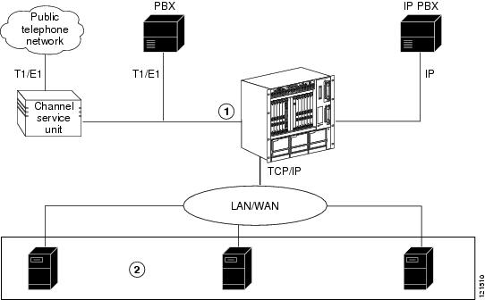
Cisco Unified MeetingPlace Audio Server resides internally on the Cisco Unified MeetingPlace 8106 or 8112. Audio Server can be integrated with your organization's standard business applications, such as e-mail, Microsoft Outlook, and IBM Lotus Notes. These server-based integration applications (for example, Cisco Unified MeetingPlace Web Conferencing and Cisco Unified MeetingPlace for Outlook) are installed on one or more Cisco Media Convergence Servers (MCS). This Cisco-provided machine (which runs on Microsoft Windows) communicates with the Audio Server system and other Cisco Unified MeetingPlace integration applications over your LAN or WAN. (For more information about the Cisco MCS, see the "About the Cisco MCS" section.)
Figure 1-1 illustrates how a Cisco Unified MeetingPlace system integrates with your network.
Figure 1-1 Cisco Unified MeetingPlace System Integrates with Your Network
Cisco Unified MeetingPlace 8106 or 8112
Cisco Media Convergence Server (MCS) with Cisco Unified MeetingPlace integration applications installed on them
About the Cisco Unified MeetingPlace Audio Server System
Cisco Unified MeetingPlace Audio Server system configurations include Cisco Unified MeetingPlace 8100 series hardware, Audio Server software, and Cisco Unified MeetingPlace desktop software components with additional software options.
This section contains the following hardware information for the Cisco Unified MeetingPlace 8100 series:
•
•
•
•
•
•
•
Hardware Characteristics of the Cisco Unified MeetingPlace 8106
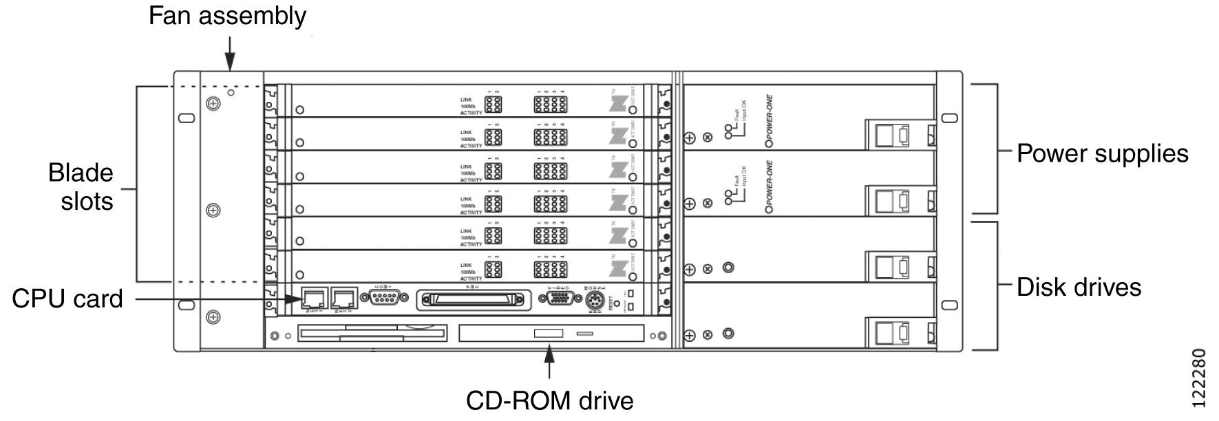
The Cisco Unified MeetingPlace 8106 is a rack-mountable box that is 7 inches tall, 18.9 inches wide, and 14.5 inches deep. Fully loaded, it weighs up to 40 pounds.
The Cisco Unified MeetingPlace 8106 has the capacity for a CPU card, six slots for Smart Blades or Multi Access Blades to provide physical connectivity to the phone network, and four drives: two disk drives, a floppy drive, and a CD-ROM drive. The front of the chassis allows access to the CPU, Smart Blades, and redundant power supplies. LAN cables, and telephony and IP cables plug into the back.
Figure 1-2 shows the Cisco Unified MeetingPlace 8106.
Figure 1-2 Cisco Unified MeetingPlace 8106 Features (Front View)
Hardware Characteristics of the Cisco Unified MeetingPlace 8112
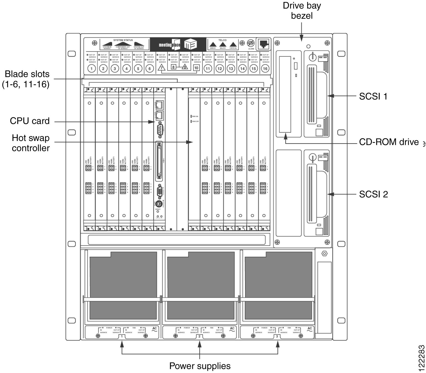
The Cisco Unified MeetingPlace 8112 is a rack-mountable box, 21 inches tall and 18.9 inches wide. Fully loaded, it weighs up to 110 pounds.
The Cisco Unified MeetingPlace 8112 has the capacity for a CPU card, a hot swap controller (HSC), 12 slots for Smart Blades or Multi Access Blades to provide physical connectivity to the phone network, and four drives: two disk drives, a floppy drive, and a CD-ROM drive. The front of the chassis allows access to the CPU, Smart Blades, and redundant power supplies. LAN cables, and telephony and IP cables plug into the back.
An alarm panel, located on the top portion of the chassis front, indicates major alarms, minor alarms, and system status. For more information on the alarm panel, see the "Alarm Panels for the Cisco Unified MeetingPlace 8112" section.
Figure 1-3 shows the Cisco Unified MeetingPlace 8112.
Figure 1-3 Cisco Unified MeetingPlace 8112 Features (Front View)
Cisco Unified MeetingPlace 8100 Series Hardware Components
Table 1-1 describes the Cisco Unified MeetingPlace 8100 series hardware components for the Audio Server.
Alarm Panels for the Cisco Unified MeetingPlace 8106
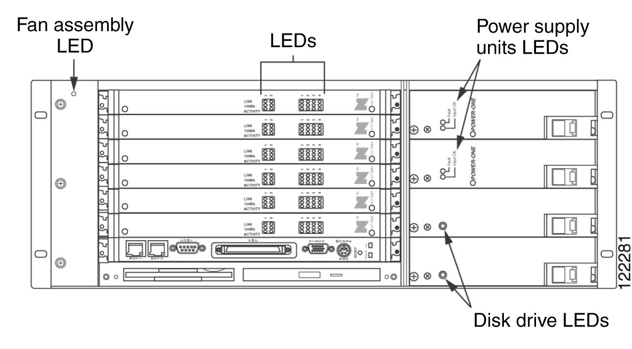
The Cisco Unified MeetingPlace 8106 has three types of LEDs as described in Table 1-2. See Figure 1-4 to locate the Cisco Unified MeetingPlace 8106 LEDs.
Figure 1-4 Locations of Cisco Unified MeetingPlace 8106 LEDs
Alarm Panels for the Cisco Unified MeetingPlace 8112
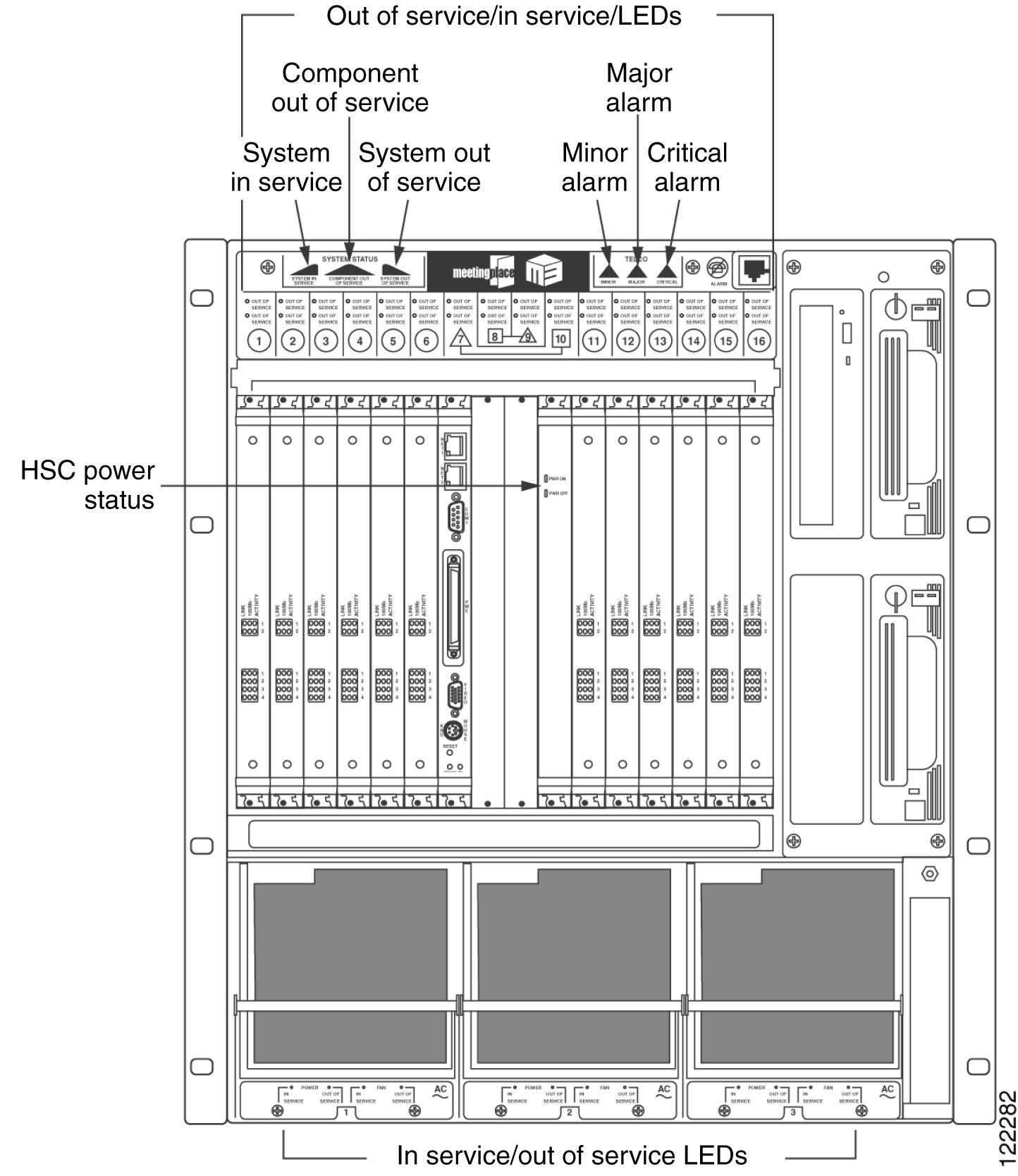
The Cisco Unified MeetingPlace 8112 has system LEDs on the front top panel, as described in Table 1-3. See Figure 1-5 to locate the Cisco Unified MeetingPlace 8112 LEDs.
Figure 1-5 Locations of Cisco Unified MeetingPlace 8112 LEDs
About Cisco Unified MeetingPlace Audio Server System Configurations
This section contains information on and examples of the different blade configurations for the Cisco Unified MeetingPlace Audio Server system. (For instructions on configuring the Audio Server system, refer to the Configuration Guide for Cisco Unified MeetingPlace Audio Server at http://www.cisco.com/en/US/products/sw/ps5664/ps5669/products_installation_and_configuration_guides_list.html.)
The Cisco Unified MeetingPlace 8106 comes equipped with six slots for Smart Blades, T1 Smart Blades, or Multi Access Blades, and the Cisco Unified MeetingPlace 8112 comes equipped with 12 slots for Smart Blades, T1 Smart Blades, or Multi Access Blades.
Table 1-4 lists the number of access ports supported per blade.
Note
Note that mixing protocols is supported only in combination with IP ports:
•
•
•
(For example, a Cisco Unified MeetingPlace system cannot have both T1 and E1 ports configured, but it can have T1—either PRI or CAS—and IP ports, or E1 and IP ports. In addition, a Cisco Unified MeetingPlace system cannot have both T1 CAS and T1 PRI ports configured.)
Note
Configuration Information and Examples for the Cisco Unified MeetingPlace 8106
The Cisco Unified MeetingPlace 8106 supports the following:
•
•
•
•
•
•
•
Table 1-5 lists the allowable port and blade configurations for each protocol and the hardware used to achieve them.
T1 CAS Smart Blades and T1 PRI and E1 Multi Access Blades are installed starting from slot 1 on the bottom and move to the top. IP Multi Access Blades are installed starting from slot 6 on the top and move to the bottom.
Example: T1 CAS Configuration
Table 1-6 shows a pure T1 CAS configuration with 576 ports. Each slot has a T1 Smart Blade, denoted by SB. Each T1 Smart Blade provides 96 ports, and there are 6 T1 Smart Blades (96 x 6 = 576).
Example: T1 PRI Configuration
Table 1-7 shows a pure T1 PRI configuration with 368 T1 PRI ports. The MP-MA-16-PRI in slot 1 provides 368 T1 PRI ports. Because Multi Access Blades do not provide conferencing capability, every 96 ports requires one Smart Blade. All of the ports in slots 2 to 4 (3 x 96 = 288) and 80 of the ports in slot 5 are used for conferencing.
Table 1-7 Pure T1 PRI Configuration, 368 T1 CAS Ports
6
5
SB
4
SB
3
SB
2
SB
1
MP-MA-16-PRI
Example: Pure IP Configuration
Table 1-8 shows a pure IP configuration with 480 IP ports. The MP-MA-16 in slot 6 provides 480 IP ports. Because Multi Access Blades do not provide conferencing capability, every 96 ports of IP requires one Smart Blade, so slots 1 to 5 use their 480 ports (5 x 96 = 480) for IP conferencing.
Examples: T1 CAS and IP Mixed Configurations
Table 1-9 through Table 1-12 show examples of T1 CAS and IP mixed configurations. The T1 CAS trunks may or may not be configured, depending on the number of IP ports. In each table, SB is a T1 Smart Blade.
In Table 1-9, the MP-MA-4 in slot 6 provides 120 IP ports. Every 96 ports of IP requires one Smart Blade, so the Smart Blade in slot 5 uses its 96 ports and the Smart Blade in slot 4 uses 24 of its 96 ports for IP conferencing (96 + 24 = 120). The remaining 72 ports in slot 4 (96 - the 24 used for the IP conferencing) plus the ports in slots 1 to 3 (3 x 96 = 288) are used for the T1 CAS portion of the configuration (288 + 72 = 360).
Table 1-9 120 IP Ports, 360 T1 CAS Ports, 480 Total Ports
6
MP-MA-4
5
SB
4
SB
3
SB
2
SB
1
SB
In Table 1-10, the MP-MA-4 in slot 6 provides 96 IP ports. Every 96 ports of IP requires one Smart Blade, so the Smart Blade in slot 5 uses its 96 ports for IP conferencing. The ports in slots 1 to 4 (96 x 4 = 384) are used for the T1 CAS portion of the configuration.
Table 1-10 96 IP Ports, 384 T1 CAS Ports, 480 Total Ports
6
MP-MA-4
5
SB
4
SB
3
SB
2
SB
1
SB
In Table 1-11, the MP-MA-16 in slot 6 provides 240 IP ports. Every 96 ports of IP requires one Smart Blade, so the Smart Blades in slot 4 and 5 use their 96 ports and the Smart Blade in slot 3 uses 48 of its 96 ports for IP conferencing (96 + 96 + 48 = 240). The remaining 48 ports in slot 3 (96 - the 48 used for the IP conferencing) plus the ports in slots 1 and 2 (2 x 96 = 192) are used for the T1 CAS portion of the configuration (48 + 192 = 240).
Table 1-11 240 IP Ports, 240 T1 CAS Ports, 480 Total Ports
6
MP-MA-16
5
SB
4
SB
3
SB
2
SB
1
SB
In Table 1-12, the MP-MA-16 in slot 6 provides 360 IP ports. Every 96 ports of IP requires one Smart Blade, so the Smart Blades in slots 3 to 5 use their 96 ports and the Smart Blade in slot 2 uses 72 of its 96 ports for IP conferencing (3 x 96 = 288 + 72 = 360). The remaining 24 ports in slot 2 (96 - the 72 used for the IP conferencing) plus the 96 ports in slot 1 are used for the T1 CAS portion of the configuration (24 + 96 = 120).
Table 1-12 360 IP Ports, 120 T1 CAS Ports, 480 Total Ports
6
MP-MA-16
5
SB
4
SB
3
SB
2
SB
1
SB
Examples: T1 PRI and IP Mixed Configurations
Table 1-13 to Table 1-16 show examples of T1 PRI and IP mixed configurations. IP Multi Access Blades are installed starting from slot 6 on the top and move to the bottom.
In Table 1-13, the MP-MA-4 in slot 6 provides 120 IP ports. Every 96 ports of IP requires one Smart Blade, so the Smart Blade in slot 4 uses its 96 ports and the Smart Blade in slot 3 uses 24 of its 96 ports for IP conferencing (96 + 24 = 120). The MP-MA-4-PRI in slot 1 provides 92 T1 PRI ports. The Smart Blade in slot 2 uses 92 of its 96 ports for conferencing.
Table 1-13 120 IP Ports, 92 T1 PRI Ports, 212 Total Ports
6
MP-MA-4
5
4
SB
3
SB
2
SB
1
MP-MA-4-PRI
In Table 1-14, the MP-MA-4 in slot 6 provides 120 IP ports. Every 96 ports of IP requires one Smart Blade, so the Smart Blade in slot 5 uses its 96 ports and the Smart Blade in slot 4 uses 24 of its 96 ports for IP conferencing (96 + 24 = 120). The MP-MA-16-PRI in slot 1 provides 253 T1 PRI ports. The Smart Blades in slots 2 and 3 use their 96 ports and the Smart Blade in slot 4 uses 61 of its 72 ports for conferencing. (The Smart Blade in slot 4 uses 24 of its ports for the IP portion of the configuration and 61 ports for the T1 PRI portion of the configuration.)
Table 1-14 120 IP Ports, 253 T1 PRI Ports, 373 Total Ports
6
MP-MA-4
5
SB
4
SB
3
SB
2
SB
1
MP-MA-16-PRI
In Table 1-15, the MP-MA-16 in slot 6 provides 240 IP ports. Every 96 ports of IP requires one Smart Blade, so the Smart Blades in slots 4 and 5 use their 96 ports and the Smart Blade in slot 3 uses 48 of its 96 ports for IP conferencing (96 + 96 + 48 = 240). The MP-MA-4-PRI in slot 1 provides 92 T1 PRI ports. The Smart Blade in slot 2 uses 92 of its 96 ports for conferencing.
Table 1-15 240 IP Ports, 92 T1 PRI Ports, 332 Total Ports
6
MP-MA-16
5
SB
4
SB
3
SB
2
SB
1
MP-MA-4-PRI
In Table 1-16, the MP-MA-16 in slot 6 provides 180 IP ports. Every 96 ports of IP requires one Smart Blade, so the Smart Blade in slot 5 uses its 96 ports and the Smart Blade in slot 4 uses 84 of its 96 ports for IP conferencing (96 + 84 = 180). The MP-MA-4-PRI in slot 1 provides 92 T1 PRI ports. The Smart Blade in slot 2 uses 92 of its 96 ports for conferencing.
Table 1-16 180 IP Ports, 92 T1 PRI Ports, 272 Total Ports
6
MP-MA-16
5
SB
4
SB
3
2
SB
1
MP-MA-4-PRI
Example: E1 Configuration
The E1 Multi Access Blade is installed in slot 1, followed by Smart Blades. Table 1-17 shows a pure E1 configuration with 480 E1 ports. The MP-MA-16-PRI in slot 1 provides 480 E1 ports. The Smart Blades in slots 2 to 6 each have 96 ports (96 x 5 = 480) which are used for conferencing. In this table, SB is a Smart Blade.
Examples: E1 and IP Mixed Configurations
The E1 Multi Access Blade is installed in slot 1, followed by Smart Blades. The IP Multi Access Blade is installed in slot 6.
Table 1-18 through Table 1-20 show examples of mixed E1 and IP configurations. The E1 trunks on the Multi Access Blades may or may not be configured depending on the number of IP Multi Access Blades populated. In the following tables, SB is a Smart Blade.
In Table 1-18, the MP-MA-4 in slot 6 provides 120 IP ports. Every 96 ports of IP requires one Smart Blade, so the Smart Blade in slot 4 uses its 96 ports and the Smart Blade in slot 3 uses 24 of its 96 ports for IP conferencing (96 + 24 = 120). The MP-MA-4-PRI in slot 1 provides 120 E1 ports. The remaining 72 ports in slot 3 (96 - the 24 used for the IP conferencing) plus 48 ports in slot 2 (72 + 48 = 120) are used for the E1 portion of the configuration.
Table 1-18 120 IP Ports, 120 E1 Ports, 240 Total Ports
6
MP-MA-4
5
4
SB
3
SB
2
SB
1
MP-MA-4-PRI
In Table 1-19, the MP-MA-4 in slot 6 provides 120 IP ports. Every 96 ports of IP requires one Smart Blade, so the Smart Blade in slot 5 uses its 96 ports and the Smart Blade in slot 4 uses 24 of its 96 ports for IP conferencing (96 + 24 = 120). The MP-MA-16-PRI in slot 1 provides 240 E1 ports. The Smart Blades in slots 2 and 3 use their 96 ports and the Smart Blade in slot 4 uses 48 of its remaining 72 ports for conferencing (96 + 96 + 48 = 240). (The Smart Blade in slot 4 uses 24 of its ports for the IP portion of the configuration and 48 ports for the E1 portion of the configuration.)
Table 1-19 120 IP Ports, 240 E1 Ports, 360 Total Ports
6
MP-MA-4
5
SB
4
SB
3
SB
2
SB
1
MP-MA-16-PRI
In Table 1-20, the MP-MA-16 in slot 6 provides 240 IP ports. Every 96 ports of IP requires one Smart Blade, so the Smart Blades in slots 4 and 5 use their 96 ports and the Smart Blade in slot 3 uses 48 of its 96 ports for IP conferencing (96 + 96 + 48 = 240). The MP-MA-4-PRI in slot 1 provides 120 E1 ports. The Smart Blade in slot 2 uses its 96 ports and the Smart Blade in slot 3 uses 24 of its remaining 48 ports for conferencing (96 + 24 = 120). (The Smart Blade in slot 4 uses 48 of its ports for the IP portion of the configuration and 24 ports for the E1 portion of the configuration.)
Table 1-20 240 IP Ports, 120 E1 Ports, 360 Total Ports
6
MP-MA-16
5
SB
4
SB
3
SB
2
SB
1
MP-MA-4-PRI
Configuration Information and Examples for the Cisco Unified MeetingPlace 8112
The Cisco Unified MeetingPlace 8112 supports the following:
•
•
•
•
•
•
•
Table 1-21 lists the allowable port and blade configurations for each protocol and the hardware used to achieve them.
T1 PRI and E1 Multi Access Blades are installed on the left (with slot 2 left vacant if no MP-MA-16-PRI or MP-MA-4-PRI is needed to populate it and if the slot is not needed for Smart Blade capacity). Next, T1 Smart Blades are installed to the right of this. Last, IP Multi Access Blades are installed starting on the right (slot 16), and move to the left.
Note
Example: T1 CAS Configuration
Table 1-22 shows a pure T1 CAS configuration with 1152 T1 CAS ports. Each slot (except for slots 7 to 10, which are reserved for CPU and system controller cards) has a T1 Smart Blade, denoted by SB. Each T1 Smart Blade has the capacity for 96 ports and there are 12 T1 Smart Blades (96 x 12 = 1152).
Table 1-22 Pure T1 CAS Configuration, 1152 T1 CAS Ports
1
2
3
4
5
6
11
12
13
14
15
16
SB
SB
SB
SB
SB
SB
SB
SB
SB
SB
SB
SB
Example: T1 PRI Configuration
Table 1-23 shows a pure T1 PRI configuration with 736 T1 PRI ports. The MP-MA-16-PRIs in slots 1 and 2 provide 368 T1 PRI ports each (368 x 2 = 736). The ports in slots 3 to 13 (7 x 96 = 672) and 64 of the ports in slot 14 are used for conferencing (672 + 64 = 736).
Table 1-23 Pure T1 PRI Configuration, 736 T1 PRI Ports
1
2
3
4
5
6
11
12
13
14
15
16
MP-MA-16-
PRIMP-MA-16-
PRISB
SB
SB
SB
SB
SB
SB
SB
Example: Pure IP Configuration
Table 1-24 shows a pure IP configuration with 960 IP ports. There are two MP-MA-16s on the right which support 480 IP ports each (2 x 480 = 960). Because Multi Access Blades do not provide conferencing capability, every 96 ports of IP requires one Smart Blade, so slots 1 to 6 and slots 11 to 14 each have a Smart Blade with a capacity for 96 ports.
Table 1-24 Pure IP Configuration, 960 IP Ports
1
2
3
4
5
6
11
12
13
14
15
16
SB
SB
SB
SB
SB
SB
SB
SB
SB
SB
MP-MA-16
MP-MA-16
Examples: T1 CAS and IP Mixed Configurations
Table 1-25 to Table 1-28 show examples of configurations with T1 CAS and IP. The T1 CAS trunks may or may not be configured depending on the number of IP ports. In each table, SB is a T1 Smart Blade.
In Table 1-25, the MP-MA-4 in slot 16 provides 120 IP ports. Every 96 ports of IP requires one Smart Blade, so the Smart Blade in slot 15 uses its 96 ports and the Smart Blade in slot 14 uses 24 of its 96 ports for IP conferencing (96 + 24 = 120). The remaining 72 ports in slot 14 (96 - the 24 used for the IP conferencing) plus the ports in slots 1 to 6 and 11 to 13 (9 x 96 = 864) are used for the T1 CAS portion of the configuration (864 + 72 = 936).
Table 1-25 120 IP Ports, 936 T1 CAS Ports, 1056 Total Ports
1
2
3
4
5
6
11
12
13
14
15
16
SB
SB
SB
SB
SB
SB
SB
SB
SB
SB
SB
MP-MA-4
In Table 1-26, the MP-MA-16 in slot 16 provides 480 IP ports. Every 96 ports of IP requires one Smart Blade, so the Smart Blades in slots 11 to 15 use their 480 ports for IP conferencing (96 x 5 = 480). Slots 1 to 6 have T1 Smart Blades with 96 ports each (6 x 96 = 576 ports) to support the T1 CAS configuration.
Table 1-26 480 IP Ports, 576 T1 CAS Ports, 1056 Total Ports
1
2
3
4
5
6
11
12
13
14
15
16
SB
SB
SB
SB
SB
SB
SB
SB
SB
SB
SB
MP-MA-16
In Table 1-27, the two MP-MA-4s in slots 15 and 16 provide 120 IP ports each (2 x 120 = 240). Every 96 ports of IP requires one Smart Blade, so the Smart Blades in slots 13 and 14 use their 96 ports and the Smart Blade in slot 12 uses 48 of its 96 ports for IP conferencing (96 + 96 + 48 = 240). The remaining 48 ports in slot 12 (96 - the 48 used for the IP conferencing) plus the ports in slots 1 to 6 and 11 (7 x 96 = 672) are used for the T1 CAS portion of the configuration (672 + 48 = 720).
Table 1-27 240 IP Ports, 720 T1 CAS Ports, 960 Total Ports
1
2
3
4
5
6
11
12
13
14
15
16
SB
SB
SB
SB
SB
SB
SB
SB
SB
SB
MP-MA-4
MP-MA-4
In Table 1-28, the MP-MA-16 in slot 16 provides 480 IP ports and the MP-MA-4 in slot 15 provides 120 IP ports, for a total of 600 IP ports. Every 96 ports of IP requires one Smart Blade, so the Smart Blades in slots 5 to 14 use their 576 ports and the Smart Blade in slot 4 uses 24 of its 96 ports for IP conferencing (96 x 6= 576 + 24 = 600). The remaining 72 ports in slot 4 (96 - the 24 used for the IP conferencing) plus the ports in slots 1 to 3 (3 x 96 = 288) are used for the T1 CAS portion of the configuration (288 + 72 = 360).
Table 1-28 600 IP Ports, 360 T1 CAS Ports, 960 Total Ports
1
2
3
4
5
6
11
12
13
14
15
16
SB
SB
SB
SB
SB
SB
SB
SB
SB
SB
MP-MA-4
MP-MA-16
Examples: T1 PRI and IP Mixed Configurations
Table 1-29 and Table 1-30 show examples of mixed configurations with T1 PRI and IP. In each table, SB is a T1 Smart Blade. The Multi Access Blade used for the IP part of the configuration is on the right, in slot 16 and the Multi Access Blade used for the T1 PRI part of the configuration is on the left, in slot 1.
In Table 1-29, the MP-MA-16 in slot 16 provides 480 IP ports. Every 96 ports of IP requires one Smart Blade, so the Smart Blades in slots 3 to 11 use their 480 ports for IP conferencing (96 x 5= 480). The MP-MA-4-PRI in slot 1 provides 92 T1 PRI ports and the Smart Blade in slot 2 uses 92 of its 96 ports for conferencing.
Table 1-29 480 IP Ports, 92 T1 PRI Ports, 572 Total Ports
1
2
3
4
5
6
11
12
13
14
15
16
MP-MA-4-PRI
SB
SB
SB
SB
SB
SB
MP-MA-16
In Table 1-30, the MP-MA-16 in slot 16 provides 480 IP ports. Every 96 ports of IP requires one Smart Blade, so the Smart Blades in slots 6 to 14 use their 480 ports for IP conferencing (96 x 5= 480). The MP-MA-16-PRI in slot 1 provides 368 T1 PRI ports. The Smart Blades in slots 2 to 4 use their 96 ports and the Smart Blade in slot 5 uses 80 of its 96 ports for conferencing (3 x 96 = 288 + 80 = 368).
Table 1-30 480 IP Ports, 368 T1 PRI Ports, 848 Total Ports
1
2
3
4
5
6
11
12
13
14
15
16
MP-MA-16-PRI
SB
SB
SB
SB
SB
SB
SB
SB
SB
MP-MA-16
Example: Pure E1 Configuration
E1 Multi Access Blades are installed starting in slot 1 and move to the right, followed by Smart Blades. Table 1-31 shows a pure E1 configuration with 960 E1 ports. The two MP-MA-16-PRIs in slots 1 and 2 provide 480 E1 ports each (480 x 2 = 960). The Smart Blades in slots 3 to 16 each have 96 ports (96 x 10 = 960) which are used for conferencing.
In this table, SB is a Smart Blade.
Table 1-31 Pure E1 Configuration, 960 E1 Ports
1
2
3
4
5
6
11
12
13
14
15
16
MP-MA-16-PRI
MP-MA-16-PRI
SB
SB
SB
SB
SB
SB
SB
SB
SB
SB
Examples: E1 and IP Mixed Slot Configurations
E1 Multi Access Blades are installed starting in slot 1 and move to the right, followed by Smart Blades. IP Multi Access Blades are installed starting in slot 16 and move to the left.
Table 1-32 to Table 1-35 show examples of mixed E1 and IP configurations. The E1 trunks on the Multi Access Blades may or may not be configured depending on the number of IP Multi Access Blades populated. In the following tables, SB is a Smart Blade.
In Table 1-32, the MP-MA-4 in slot 16 provides 120 IP ports. Every 96 ports of IP requires one Smart Blade, so the Smart Blade in slot 12 uses its 96 ports and the Smart Blade in slot 11 uses 24 of its 96 ports for IP conferencing (96 + 24 = 120). The MP-MA-16-PRI in slot 1 provides 480 E1 ports. The remaining 72 ports in slot 11 (96 - the 24 used for the IP conferencing) plus the ports in slots 2 to 6 (5 x 96 = 480) are used for the E1 portion of the configuration (5 x 96 = 480).
Table 1-32 120 IP Ports, 480 E1 Ports, 600 Total Ports
1
2
3
4
5
6
11
12
13
14
15
16
MP-MA-16-PRI
SB
SB
SB
SB
SB
SB
SB
MP-MA-4
In Table 1-33, the MP-MA-16 in slot 16 provides 480 IP ports. Every 96 ports of IP requires one Smart Blade, so the Smart Blades in slots 11 to 15 use their 96 ports for IP conferencing (96 x 5 = 480). The MP-MA-16-PRI in slot 1 provides 480 E1 ports. The ports in slot 2 to 6 (5 x 96 = 480) are used for the E1 portion of the configuration.
Table 1-33 480 IP Ports, 480 E1 Ports, 960 Total Ports
1
2
3
4
5
6
11
12
13
14
15
16
MP-MA-16-PRI
SB
SB
SB
SB
SB
SB
SB
SB
SB
SB
MP-MA-16
In Table 1-34, the MP-MA-16 in slot 16 provides 480 IP ports. Every 96 ports of IP requires one Smart Blade, so the Smart Blades in slots 4 to 12 use their 96 ports for IP conferencing (96 x 5 = 480). The MP-MA-4-PRI in slot 1 provides 120 E1 ports. The 96 ports in slot 2 plus 24 of the ports in slot 3 are used for the E1 portion of the configuration (96 + 24 = 120).
Table 1-34 480 IP Ports, 120 E1 Ports, 600 Total Ports
1
2
3
4
5
6
11
12
13
14
15
16
MP-MA-4-PRI
SB
SB
SB
SB
SB
SB
SB
MP-MA-16
In Table 1-35, the MP-MA-4 in slot 16 provides 120 IP ports. Every 96 ports of IP requires one Smart Blade, so the Smart Blade in slot 4 uses its 96 ports and the Smart Blade in slot 3 uses 24 of its 96 ports for IP conferencing (96 + 24 = 120). The MP-MA-4-PRI in slot 1 provides 120 E1 ports. The 96 ports in slot 2 plus 24 of the unused ports in slot 3 are used for the E1 portion of the configuration (96 + 24 = 120).
Table 1-35 120 IP Ports, 120 E1 Ports, 240 Total Ports
1
2
3
4
5
6
11
12
13
14
15
16
MP-MA-4-PRI
SB
SB
SB
MP-MA-4
Cisco Unified MeetingPlace Audio Server Software
The Cisco Unified MeetingPlace Audio Server software uses a client server architecture that divides computing tasks between the server and the client. The following software resides on the Cisco Unified MeetingPlace system database disk:
•
•
–
–
–
Desktop software is installed on desktop computers. This software communicates with the Cisco Unified MeetingPlace system over the LAN or WAN.
For a list of all Cisco Unified MeetingPlace Audio Server software options, see the "About Cisco Unified MeetingPlace Integration Applications" section.
Table 1-36 describes the components of the Cisco Unified MeetingPlace voice-only (Audio Server) configuration.
About Cisco Unified MeetingPlace Integration Applications
Cisco Unified MeetingPlace provides server-software options that integrate with Cisco Unified MeetingPlace Audio Server.
Table 1-37 describes these additional integration applications.
About the Cisco MCS
To ensure a consistent operating environment for Cisco Unified MeetingPlace integration applications, all new installations of Cisco Unified MeetingPlace integration software must be installed on a Cisco Media Convergence Server (MCS) 7835 or Cisco MCS 7845, a Microsoft Windows software-based server.
The Cisco MCS is not shipped with an installed operating system. A Cisco Systems version of Microsoft Windows 2000 Server is provided on a CD-ROM and shipped with applicable software applications that run on the Cisco MCS hardware.
This section contains the following information:
•
•
Cisco MCS Requirements
The type of Cisco MCS and the number of MCSs you need depend on the following:
•
•
For information on specific requirements, refer to System Requirements for Cisco Unified MeetingPlace at http://www.cisco.com/en/US/products/sw/ps5664/ps5669/prod_installation_guides_list.html.
Installing the Cisco MCS Operating System
Before you install any Cisco Unified MeetingPlace software on the Cisco MCS, install the operating system. Follow the procedure in Installing the Operating System on the Cisco IP Telephony Applications Server (version 2000.2.4 or later), which is included with the operating system software. Although the document refers to Cisco Unified CallManager and other applications, it also applies to Cisco Unified MeetingPlace integration applications.
You will need the following product key during the installation: BTOO VQES CCJU IEBI.
Caution
If your network operates reliably at 100 MBps, set the Cisco MCS Ethernet Interface for 100 MB Full Duplex. Otherwise, set the interface for Autonegotiate.
Updating the Cisco MCS Operating System
You must update the Cisco operating system only with upgrades and patches issued by Cisco.
Caution
Installation Order of Cisco Unified MeetingPlace Components
This section describes the order in which the Cisco Unified MeetingPlace components and integration applications should be installed on a Cisco MCS 7835 or Cisco MCS 7845:
•
•
Caution
Installation Order for One Cisco MCS
If you are using one MCS, install the following Cisco Unified MeetingPlace components in the order listed.
1.
Loading Cisco Unified MeetingPlace H.323/SIP IP Gateway first allows you to test dial-in access to the Audio Server system. Then you can confirm that the Cisco Unified MeetingPlace 8106 or Cisco Unified MeetingPlace 8112 is functioning correctly before any critical Cisco Unified MeetingPlace integration applications are installed.
2.
3.
4.
5.
•
•
•
6.
Installation Order for a Second MCS
If you are using a second Cisco MCS, install the following Cisco Unified MeetingPlace components in the order listed.
1.
2.
Note
Cisco Unified MeetingPlace Component Compatibility Matrix
Table 1-38 shows the releases of Cisco Unified MeetingPlace applications that are compatible with Cisco Unified MeetingPlace Audio Server Release 5.4.
Table 1-38 Component Compatibility with Cisco Unified MeetingPlace Audio Server 5.4
Cisco Unified MeetingPlace Directory Services
5.4(x)
Cisco Unified MeetingPlace for Lotus Notes
5.4(x)
5.3(x)1
Cisco Unified MeetingPlace for Outlook
5.4(x)
5.3(x)1
Cisco Unified MeetingPlace Gateway SIM
5.2(x)
Cisco Unified MeetingPlace H.323/SIP Gateway
5.4(x)
Cisco Unified MeetingPlace Jabber Integration
5.4(x)
Cisco Unified MeetingPlace Network Backup Gateway
5.3(x)
Cisco Unified MeetingPlace SMTP E-Mail Gateway
5.4(x)
5.3(x)1
Cisco Unified MeetingPlace Video Integration
5.4(x)
Cisco Unified MeetingPlace Web Conferencing
5.4(x)
5.3(x)1
MeetingTime
5.4(x) (Required for system administrators.)
5.3(x)1 (End users may use.)
Video Administration for Cisco Unified MeetingPlace
5.4(x)
1 Some features may not function correctly.
For requirement information on individual components, refer to System Requirements for Cisco Unified MeetingPlace at http://www.cisco.com/en/US/products/sw/ps5664/ps5669/prod_installation_guides_list.html.