Feedback
Contents
- Administer and Configure MediaSense
- Access MediaSense Administration
- Single sign-in
- MediaSense Administration
- Unified CM configuration
- Unified CM user information and MediaSense setup
- Select AXL service providers
- Select call control service providers
- Replace Unified CM service providers
- MediaSense setup with Finesse
- Cisco Finesse configuration
- Provision users for MediaSense deployment
- MediaSense API users
- API user configuration
- Storage management agent
- Pruning Options
- Prune Policy Configuration
- Storage threshold values and pruning avoidance
- System thresholds
- View disk space use
- Storage use information obtained using HTTP
- Storage use information obtained by using Unified RTMT
- Incoming Call Configuration
- Add Incoming Call Rule
- Edit Incoming Call Rule
- Edit System Default Incoming Call Rule
- Delete Incoming Call Rule
- Media File Management
- Media File Details
- Add Media File
- Edit Media File
- Redeploy Media File
- Delete Media File
- Refresh media file
- MediaSense server configuration
- Media partition management
- Configure Media Partitions
- Event management
- Enable event forwarding
- MediaSense setup with Cisco Unified Border Element
- Manage Unified CM users
- Cisco MediaSense provisioning for CUBE
- CUBE and MediaSense setup
- CUBE gateway accessibility
- CUBE view configuration commands
- Global-level interoperability and MediaSense setup
- Setup global level
- Dial-peer level setup
- Set up CUBE dial-peers for MediaSense deployments
- CUBE deployments log commands
- Access MediaSense Serviceability
- MediaSense Serviceability
- Trace setup
- Trace files
- Trace log levels
- Trace flags
- Trace file location
- Set up trace file information
- Trace file interpretation
- Performance logging
- Dump trace parameters
- Serviceability tools
- Control center network services
- Manage network services
- Control center feature services
- Manage feature services
- Media service call control service or database service reactivation
- Access serviceability user interface for other servers in cluster
- Unified RTMT administration
- Unified RTMT installation and setup
- Download the Unified RTMT plug-in
- Unified RTMT upgrade
- Unified RTMT multiple copy installations
- Server status monitoring
- Performance monitoring counters
- Unified RTMT for performance monitoring
- System condition and perfmon counter alerts
- AMC service and Unified CM setup
- Trace and log central Unified RTMT setup
- File collection
- Crash dump collection
- Remote browse folder names and services
- Perfmon agent and counters
- Server IP address changes
- Prepare system for IP address change
- Change IP address of primary server
- Change IP address of secondary server
- Change IP address of expansion server
- Change multiple IP addresses in a MediaSense cluster
- MediaSense command line interface (CLI) commands
- CLI access
- Utils commands
- utils media recording_sessions
- utils service
- utils system maintenance
- Run commands
- run db_reset_replication
- run db_synchronization
- Set network commands
- set network cluster server ip
- set network cluster primary ip
- set network cluster secondary ip
- set network ip eth0
- Show commands
- show db_synchronization status
- show network cluster
- show tech call_control_service
Administer and Configure MediaSense
The MediaSense Administration interface allows you to administer and configure the MediaSense system. You can use a web browser located on any computer on the Unified Communications network to configure and administer your applications with the MediaSense Administration web interface pages.
- Access MediaSense Administration
- Single sign-in
- MediaSense Administration
- Access MediaSense Serviceability
- MediaSense Serviceability
- Server IP address changes
- MediaSense command line interface (CLI) commands
- Utils commands
- Run commands
- Set network commands
- Show commands
Access MediaSense Administration
ProcedureTo access MediaSense Administration, you need the application administrator user ID and case-sensitive password that were defined when you installed MediaSense. (If unsure, check your installation and configuration worksheet.) These credentials must be the same for all servers in the cluster.
Single sign-in
The Navigation drop-down box in the top right corner of each Administration interface provides a list of applications or pages which you can access with a single sign-in. After you sign in to MediaSense Administration, you can access the following applications:
- Cisco MediaSense Administration Used to configure Unified CM, MediaSense users, prune policy, and to perform other tasks described in this section.
- Cisco MediaSense Serviceability Used to configure trace files and to enable and disable MediaSense services.
- Cisco Unified Serviceability Used to configure trace files and alarms and enable and disable Cisco Unified Communications services. You must be an end user on the configured Unified CM with Administrator privileges for MediaSense to sign into this application.
- Cisco Unified OS Administration Used to configure and administer the Cisco Unified Communications platform for MediaSense.
Caution
Cisco Unified OS Administration requires a separate (Unified CM) authentication procedure. You must be an end user on the configured Unified CM with Administrator privileges for MediaSense to sign into this application.To access these pages from MediaSense Administration, select the required application from the Navigation drop-down list and click Go.
All MediaSense Administration pages provide descriptive tool tips for each parameter and field. When you place your mouse over the required parameter or field, the tip is briefly displayed for each element.
This document focuses on the functions and services accessed from the Cisco MediaSense Administration and Cisco MediaSense Serviceability pages. When actions are required on the Cisco Unified Serviceability and Cisco Unified OS Administration pages, it is clearly identified where to perform these actions.
The minimum supported screen resolution specifies 1024x768. Devices with lower screen resolutions may not display the applications correctly.
MediaSense Administration
The MediaSense Administration menu bar on the left side of the screen contains the following menu options:
- Administration—Contains options for configuring new servers in the cluster, Unified CM information, and changing system parameters.
- System—Allows you to add a new server or view the disk usage information for each server in the MediaSense deployment.
- Help—Provides access to online help for MediaSense.
- To display documentation for the active administration interface window, click Help > This Page .
- To verify the version of the administration running on the server, click Help > About or click the About link in the upper-right corner of the window.
- To view the latest version of all documents for this release, click Help > Cisco.com. If you are connected to the external network, this link connects you to the home page for Cisco MediaSense.
- To view the latest version of the troubleshooting tips for this release, click Help > Troubleshooting Tips . If you are connected to the external network, this link connects you to the Trouble Shooting page for Cisco MediaSense.
Unified CM configuration
The topics in the section pertain to a Unified CM cluster and assume that the user has both Unified CM and MediaSense administrator privileges.
- Unified CM user information and MediaSense setup
- MediaSense setup with Finesse
- Provision users for MediaSense deployment
- Storage management agent
- Incoming Call Configuration
- Media File Management
- MediaSense server configuration
- Media partition management
- Event management
Unified CM user information and MediaSense setup
When you access MediaSense Administration for the first time for a given cluster, the system automatically initiates the cluster setup procedure that is described in the Post-installation tasks section.
- Select AXL service providers
- Select call control service providers
- Replace Unified CM service providers
Select AXL service providers
ProcedureDuring the MediaSense post-installation setup process, you may have provided the AXL information for the primary server. If you did not provide this information during the post-installation process or if you need to modify the AXL information, you can do so by following the procedure provided in this section.
Based on the primary server information, MediaSense Administration retrieves the list of other Unified Communications Manager servers in the cluster and displays them in the list of available Unified Communications Manager servers. You can select the required server (or servers) and change the Administrative XML Layer (AXL) user information.
Note
The AXL service must be enabled for the required Unified Communications Manager server (or servers) before MediaSense Administration can access that server to update the AXL user information.
To modify the AXL information for MediaSense, complete the following procedure.
Select call control service providers
ProcedureDuring the MediaSense installation process, you provided the information for the first Unified Communications Manager server. Based on the primary server information, MediaSense retrieves the list of other Unified Communications Manager servers in the cluster and displays them in the list of available Unified Communications Manager servers. You can select the required server so that the MediaSense call control service can determine the Unified Communications Manager server to which the outbound call must be sent. If you select multiple Unified Communications Manager servers, you ensure that the outbound call is placed even if one of the servers is not functional.
To modify the call control service information for MediaSense, complete the following procedure.
Step 1 From MediaSense Administration, select Administration > Unified CM Configuration. The Cisco Unified CM Configuration web page opens.
Step 2 In the Unified CM Configuration web page, go to the Call Control Service Provider Configuration section to modify the call control service provider information.
Note If you deselect the Unified CM server from the Selected list box, a browser window pops up informing you about the deselected servers.
Caution If you modify the Unified CM cluster and do not select the required call control service providers for the new Unified CM server, the MediaSense call control service will be out of service (OOS) and outbound call recording will be disabled.
Step 3 Click the Save icon at the top of the Cisco Unified CM Configuration web page to save your changes. The Unified CM Configuration web page refreshes to display the new settings.
Replace Unified CM service providers
ProcedureIn the Unified CM Configuration web page, you can select Unified CM servers from the available list. However, you cannot modify the IP address for a selected service provider.
To modify the IP addresses that show up in the Available list, you must first add a new AXL service provider.
Caution
If you modify the Unified CM cluster configuration, you must also reconfigure the MediaSense API users. If you do not reconfigure the corresponding users, you will not be able to sign in to use your MediaSense APIs.To replace the Unified CM service provider, complete the following procedure.
Step 1 From MediaSense Administration, select Administration > Unified CM Configuration. The Unified CM Configuration web page opens.
Step 2 In the Unified CM Configuration web page, click Modify Unified CM Cluster to replace the existing list of service providers. The Modifying Unified CM Cluster web page opens.
Step 3 Enter the IP address, username, and password for the new service provider in the required Unified CM cluster. If you change your mind about this new server, click Reset to go back to the Unified CM Configuration web page without making any changes.
Step 4 Click the Save icon at the top of the Add New AXL Service Provider web page to save your changes. The initial list of selected AXL service providers on the Unified CM Configuration web page will be replaced with the selected Unified CM service provider.
The MediaSense server validates the connection details, closes the Modifying Unified CM Cluster web page, and refreshes the Unified CM Configuration web page to display the new service provider in the Selected service provider list. The selected service provider is also updated in the MediaSense database.
Even if you provide only one Unified CM IP address in this page, the other service provider IP addresses in this Unified CM cluster will automatically appear in the list of Available service providers (both AXL and Call Control service providers).
Step 5 The list of Available Call Control Service Providers is also updated automatically for the newly selected service provider. Select and move the required Unified CM servers from the Available Call Control Service Provider list to the Selected Call Control Service Provider list using the right arrow. If you do not select the required Call Control Service Providers for the new Unified CM server, the MediaSense Call Control Service will be Out Of Service (OOS) and the outbound call recording will be disabled.
Caution If you modify the Unified CM cluster and do not select the required call control service providers for the new Unified CM server, the MediaSense call control service will be out of service (OOS) and outbound call recording will be disabled.
Note If you modify the Unified CM service provider configuration, you must also reconfigure the MediaSense API users. If you do not reconfigure the corresponding users, you will not be able to sign in to use your MediaSense APIs.
Step 6 Click the Save icon at the top of the Cisco Unified CM Configuration web page to save your changes. The MediaSense server validates the Selected Call Control Service Providers and saves this information to the database.
MediaSense setup with Finesse
This section provides the information required to set up MediaSense so that all Finesse supervisors can use the Search and Play application (without additional authentication). This is an optional feature.
Cisco Finesse configuration
ProcedureUse the Finesse configuration screen to identify two IP addresses by which Finesse and MediaSense can communicate user authentication information between the two systems.
Step 1 From MediaSense Administration, select Administration > Cisco Finesse Configuration. Step 2 In the Primary Cisco Finesse IP or hostname field, enter the IP address or hostname of the Finesse server that you want as the primary server for MediaSense to communicate with. Step 3 Optionally, in the Secondary Cisco Finesse IP or hostname field, enter the IP address or hostname of the Finesse server that you want as the secondary server for MediaSense to communicate with. Note that in order to define a secondary server, a primary server must first be defined.
Step 4 Click the Save icon at the top of the page to save your changes. To reset the servers, click Reset and repeat these steps.
Provision users for MediaSense deployment
You can provision Unified CM end users as Application Programming Interface (API) users in MediaSense deployments. Only the MediaSense application administrator can provide API access for Unified CM end users.
MediaSense API users
The MediaSense open Application Programming Interface (API) list is available for third-party users to securely perform the following functions:
- Pause and resume, hold and resume, or conference and transfer a recording while in progress.
- Control a recorded session.
- Search and manage existing recordings.
- Monitor a live session.
MediaSense APIs provide an alternate to the functionality that is available through the MediaSense web interface. Using these APIs, users can create customized client applications. System integrators and developers who want to use MediaSense to integrate with other Unified Communications software or any third-party software applications need to have access to the MediaSense API. See Unified CM user information and MediaSense setup.
API user configuration
ProcedureMediaSense API users can use various MediaSense APIs to perform various functions with the captured recordings.
For more details about API usage, you must first provision Unified CM end users as API users in MediaSense Administration.
Caution
If you modify the Unified CM cluster configuration, you must reconfigure the MediaSense API users. If you do not reconfigure the corresponding users, you will not be able to sign in to use your MediaSense APIs.
Step 1 From MediaSense Administration, select Administration > MediaSense API User Configuration . The MediaSense API User Configuration screen displays the MediaSense User List of the first 75 configured MediaSense API users. You can sort the list by any of the columns, in both ascending and descending order.
Step 2 To modify the list, click Manage MediaSense Users. The MediaSense API User Configuration screen displays the available Unified CM users in the Available Unified CM Users list and the configured API users in the MediaSense API Users list.
Step 3 To search for users from the Unified CM list, enter the appropriate user ID (or part of the ID) in the Search for Available Unified CM Users field and click Search. The search results display all available users where the ID of the user contains the specified search text. The results of the search are listed in random order. If the search finds more than 75 users, only the first 75 are listed.
Note The returned list only displays users that are available (not already provisioned for MediaSense). As a result, the list may contain fewer than 75 users even if there are that many end users in Unified CM that meet the search criteria.
Step 4 Use the left and right arrows to make the required modifications to the MediaSense user list and click Save. The MediaSense API User Configuration screen refreshes to display your saved changes.
Click Reset, to have all settings revert to the previously configured list of users.
Click Back to User List to return to the MediaSense User List .
Storage management agent
MediaSense deployments have a central storage management service called the storage management agent (SM agent). The SM agent provisions media, monitors storage capacity, and alerts system administrators when various media and storage-related thresholds are reached.
- Pruning Options
- Storage threshold values and pruning avoidance
- System thresholds
- Storage use information obtained using HTTP
- Storage use information obtained by using Unified RTMT
Pruning Options
MediaSense deployments provide pruning options to address varied deployment scenarios. Pruning options are specified on the Administration > Prune Policy Configuration page.
These pruning options allow you to enter the following modes:
- New Recording Priority mode—In this mode, the priority is on providing space for newer recordings, by automatically pruning older recordings. This is the default behavior. The default age after which recordings will be pruned is 60 days. Old recordings will also be pruned if disk space is required for new recordings.
- Old Recording Retention mode—In this mode, priority is placed on retaining older recordings. Old recordings are not automatically pruned.
To focus priority on making new recordings in the New Recording Priority mode, mark the check box for Automatically prune recordings after they are more than __days old, and when disk space is needed for new recordings. When this check box is marked, a recording is deleted when one of the following conditions is met:
- The age of the recording is equal to or greater than the retention age that you specify in the field for this option (valid range is from 1 to 3650 days). For example, if you are within your disk usage percentage and if you automatically wish to delete all recordings older than 90 days, you must enter 90 in the Automatically prune recordings after they are more than __days old, and when disk space is needed for new recordings field. In this case, all recordings which are older than 90 days are automatically deleted. The default value is 60 days.
Note
A day is identified as 24 hours from the precise time you change this setting—it is not identified as a calendar day. For example, if you change the retention period at 23.15.01 on April 2, 2010, the specified recordings will be deleted only at 23.15.01 on April 3, 2010. The recordings will not be deleted at 00:00:01 on April 3, 2010.
- The disk usage has crossed the 90% mark. When the disk usage crosses the 90% mark, some sessions are pruned based on age criteria. This pruning continues until the disk usage is acceptable.
Note
- When you use this option to automatically delete recordings, MediaSense removes older recording data irrespective of contents. The priority is provided to newly recorded media and disk space is overwritten to accommodate new recordings.
- If you wish to use the preceding option (New Recording Priority mode) and, at the same time, wish to protect a particular session from being automatically pruned, be sure to store that session in MP4 format, download the MP4 file, and save it to a suitable location in your network. You can also use the downloadUrl parameter in the Session Query APIs and download the raw recording to a location of your choice.
When sessions are pruned, the corresponding metadata is not removed from the database; nor is the data marked as deleted in the database. MediaSense also provides options (radio buttons) that allow you to choose (or decline) to have this associated session data removed automatically.
The following options allow you choose how to handle data associated with pruned sessions:
- To have MediaSense remove the associated data automatically, select the Automatically remove associated data and mp4 files radio button.
- If you select the Do not automatically remove associated data and mp4 files radio button, the associated data will not be removed automatically. Instead, your client application must explicitly remove automatically pruned recordings, by way of the getAllPrunedSessions API and the deleteSessions API. When the deleteSessions API is executed, the metadata is marked as deleted, and the mp4 files are deleted.
To place the priority on retaining older recordings (Old Recording Retention mode), uncheck the Automatically prune recordings after they are more than __days old, and when disk space is needed for new recordings check box. If this check box is unchecked, Cisco MediaSense does not automatically prune data. Instead, you must use your client application to remove unwanted data and free up disk space. See the Developer Guide for Cisco MediaSense ) at http://www.cisco.com/en/US/products/ps11389/products_programming_reference_guides_list.html for more information.
Caution
If you do not clean up unwanted data periodically, the call control service rejects new calls and drops existing recordings at the emergency threshold level (ENTER_EMERGENCY_STORAGE_SPACE). See Storage threshold values and pruning avoidance for more details.Prune Policy Configuration
ProcedureUse the following information to set up automatic pruning (New Recording Priority mode).
To specify that MediaSense should automatically prune recordings based on age and disk space (New Recording Priority mode) use the Automatically prune recordings after they are more than __days old, and when disk space is needed for new recordings check box. Be sure to specify the age for recordings (the age at which they will be pruned) in the field provided.
Warning
When you change the number of days to delete old recordings, or change the pruning policy (check or uncheck the check box) your service will be disrupted and you must restart MediaSense Media Service for all nodes in the cluster. Be sure to make this change during your regularly scheduled downtime to avoid service interruptions.
Warning
If MediaSense is not configured to automatically prune recordings, and you change this behavior by using the Automatically prune recordings after they are more than__days old, and when disk space is needed for new recordings option, a significant amount of pruning activity may begin. This increase in pruning activity could temporarily impact system performance.
To configure the age threshold (number of days) for automatic deletion of old recordings, follow this procedure:
Step 1 From MediaSense Administration, select Administration > Prune Policy Configuration . The MediaSense Prune Policy Configuration web page opens to display the configured number of days in the Automatically prune recordings after they are more than __days old, and when disk space is needed for new recordings field. The valid range is from 1 to 3650 days, the default is 60 days.
Step 2 Change the value in this field as you require, and ensure that the corresponding check box is checked. Step 3 If you want MediaSense to automatically remove associated session data and mp4 files, select the Automatically remove associated data and mp4 files radio button. If you want your client application to handle removal of associated data and mp4 files, select the Do not automatically remove associated data and mp4 files radio button. After you specify your options, click Save to apply the changes. The page refreshes to display the new settings.
Storage threshold values and pruning avoidance
An API event is issued each time the media disk space (which stores the recorded media) reaches various thresholds. You can uncheck the Automatically prune recordings after they are more than __days old, and when disk space is needed for new recordings option and judiciously follow all threshold alerts by deleting unwanted recordings. By doing so, you can conserve space for the recordings that are required.
The other option to avoid data loss is to check the Automatically prune recordings after they are more than __days old, and when disk space is needed for new recordings option and then save the required recordings as MP4 files to a safe location in your network.
For more information about these options see Pruning Options.
The threshold value percentages and the corresponding implications are provided in the following table:
Table 1 Storage threshold values Threshold storage
Percentage
Description
ENTER_LOW_ STORAGE_SPACE
Recorded media crossed the 75% storage utilization mark.
First warning to indicate that the disk storage is running into low space condition.
EXIT_LOW_ STORAGE_SPACE
Recorded media usage dropped below 70% utilization mark.
The disk storage is exiting the low storage space condition.
ENTER_CRITICAL_ STORAGE_SPACE
Recorded media crossed the 90% local storage utilization mark.
Second warning. When entering this condition, action must be taken to guarantee future recording resources on this server.
If operating in the old recording retention mode (no automatic pruning), new recording sessions are not accepted when you reach this threshold.
If operating in the new recording priority mode, older recordings are subject to automatic deletion (to make room for new recordings).
EXIT_CRITICAL_ STORAGE_SPACE
Recorded media usage dropped below the 85% utilization mark.
The disk storage is exiting the critical storage space condition. At this point the local server is still considered to be low on resources.
In the new recording priority mode, the default pruning stops and only retention-based pruning is in effect.
ENTER_EMERGENCY_ STORAGE_SPACE
Recorded media crossed the 99% storage utilization mark.
Last warning. When the disk storage enters this condition, you must take action to guarantee future recording resources on this server.
In addition to actions taken when in CRITICAL condition, all ongoing recordings are dropped and the node is considered out-of-service for recording purposes.
EXIT_EMERGENCY_ STORAGE_SPACE -
Recorded media usage dropped below the 97% utilization mark.
The disk storage is exiting the emergency storage space condition. At this point, the local server is still considered to be low on resources and new recording sessions are still not accepted in the retention priority mode.
In new recording priority mode, the server will process new recording requests.
See the MediaSense Developer Guide at http://www.cisco.com/en/US/products/ps11389/products_programming_reference_guides_list.html for more details about the corresponding APIs, Events, and error code descriptions.
The following APIs and events correspond to this task:
System thresholds
The storage thresholds are monitored by the storage management agent (SM agent) on a per server basis. The thresholds are for the total space used on each server and do not attempt to distinguish between the media types being stored.
Periodic storage capacity checks are performed to maintain the health of the system and recordings.
View disk space use
ProcedureTo monitor the disk space used on each server in the MediaSense cluster, follow the procedure identified in this section.
Caution
If the server is not started, or is in an unknown state or is not responding, then the disk use information is not displayed. You may need to verify the state of your server to verify if it is reachable (using the ping command).See Storage threshold values and pruning avoidance for more information about threshold value percentages.
Step 1 From MediaSense Administration, select System > Disk Usage. The MediaSense Server Disk Space Usage web page is displayed.
Step 2 In the Server Disk Space Usage web page, select the required server from the Select Server drop-down list and click Go. The Server Disk Space Usage web page refreshes to display the disk space used for the selected server in gigabytes (GB) or terabytes (TB) depending on the size of the disk drive. This page is read-only.
If the selected server does not display any information in this web page, you may receive an alert informing you that the disk usage information is not available for this server. If you receive this message, verify the state of the server to ensure that the server is set up and functioning.
Storage use information obtained using HTTP
You can also obtain the current storage use information using HTTP GET requests. The URL for accessing this information is:
http://<server-ip-address>/storagemanageragent/usage.xml
The storage use information is provided in an XML format.
- Example 1— Does not use any media disks:
<?xml version="1.0" encoding="UTF-8" ?> - <storageUsageInfo date="Oct 26 2010" time="13:24:22" gmt="1288124662599"> - <partitions> <partition name="/common" size="655G" usage="29%" /> </partitions> </storageUsageInfo>- Example 2—Uses two media partitions:
                <?xml version="1.0" encoding="UTF-8" ?>
                <storageUsageInfo date="Oct 26 2010" time="13:10:53" gmt="1288123853753">
                 <partitions>
                  <partition name="/media1" size="200G" usage="5%" />
                  <partition name="/media2" size="200G" usage="50%" />
                  </partitions>
                  </storageUsageInfo>
Note
The number of media partitions directly corresponds to the number of configured media disks. If you configure two media disks, you see two media partitions: /media1 and /media2.Storage use information obtained by using Unified RTMT
The disk use monitoring category charts the percentage of disk use for the common and media partitions. It also displays the percentage of disk use for each partition (Active, Boot, Common, Inactive, Swap, Shared Memory, Spare) in each host. The Log Partition Monitoring Tool is installed automatically with the system and starts automatically after the system installation process is complete.
Note
If more than one logical disk drive is available in your system, the Cisco Unified Real Time Monitoring Tool (Unified RTMT) can monitor the disk use for the additional partition in the Disk Usage window.Unified RTMT displays all partitions in MediaSense and in the Unified Communications OS. Depending on the number of disks installed, the corresponding number of media partitions are visible in the Disk Usage window. If you do not install any media partitions, only Partition Usage (common media) is visible.
Caution
The MediaSense SM agent must be running to view media disk use information in both the Disk Usage window and the Performance window in Unified RTMT.While real time media partition use is visible in the Disk Usage window, historical partition use details are visible as performance counters in the Performance window.
Incoming Call Configuration
MediaSense enables you to assign one incoming call rule to each endpoint in the contact center. Acting on an incoming call rule, each endpoint can:
- Record incoming calls
- Play an outgoing media file once
- Play an outgoing media file continuously
- Reject incoming calls
MediaSense provides an editable system default rule. Until you assign another action as the system default rule, MediaSense defaults to recording the call. This system default rule appears in the first row in the list of incoming call rules on the Incoming Call Configuration screen, regardless of how you sort the list.
If no incoming call rule has been assigned to an endpoint, MediaSense falls back on the system default rule when an incoming call arrives at that endpoint.
Incoming Call Rules List
The Incoming Call Configuration screen displays a read-only list of the incoming call rules for each endpoint in the contact center. Displayed in rows, you can view the address of an endpoint and the action which is incoming call rule for that endpoint. When the call rule is Play Once or Play Continuously, the list also displays the title of the media file that is assigned to that endpoint.
System-assigned lock icons identify any incoming call rules which cannot be edited or deleted.
Address Requirements
Valid addresses must:
- Consist of the legal user portion of a SIP URL. For example, the legal user portion of the SIP URL john123@yourcompany.com is the user name, john123.
- Be assigned to only one incoming call rule at a time. You can assign this rule or do nothing and allow the endpoint to use the editable system default rule.
- Add Incoming Call Rule
- Edit Incoming Call Rule
- Edit System Default Incoming Call Rule
- Delete Incoming Call Rule
Add Incoming Call Rule
ProcedureAn endpoint address can be assigned to only one incoming call rule. If you do not assign an incoming call rule to an endpoint, the endpoint uses the system default call rule.
Step 1 From the Administration menu, select Incoming Call Rule Configuration. Step 2 On the Incoming Call Rule Configuration toolbar, click Add. Step 3 On the Add Incoming Call Rule screen, go to the Address field and enter the legal user portion of a SIP URL.
Example:For example, if the SIP URL is 578452@yourcompany.com, its legal user portion is john123. Often the legal user portion of SIP URLs for Videos in Queue are all numeric. So for a SIP URL such as 5551212@yourcompany.com, the legal user portion is simply 5551212.Step 4 From the Action drop-down list, select an incoming call rule. Possible values include Play Continuously, Play Once, Record, or Reject. Step 5 Click Save. MediaSense returns you to the Incoming Call Rule Configuration screen. The top of this screen displays the message Rule saved. The new incoming call rule appears in the Incoming Call Rules list.
Edit Incoming Call Rule
ProcedureYou can edit an incoming call rule by changing its address, changing its action, or changing both its address and its action. The address must be the legal user portion of a SIP URL.
Step 1 From the Administration menu, select Incoming Call Rule Configuration. Step 2 At the bottom of the Incoming Call Rule Configuration screen, go to the Incoming Call Rules list and select the radio button for the call rule that you want to edit. Step 3 On the Incoming Call Rule Configuration toolbar, click Edit. Step 4 (Optional) On the Edit Incoming Call Rule screen, go to the Address field and enter the legal user portion of a different SIP URL.
Example:If the SIP URL is 5551212@yourcompany.com, the legal user portion is 5551212.Step 5 (Optional) On the Edit Incoming Call Rule screen, go to the Action drop-down list and select a different incoming call rule for the endpoint. Step 6 If you selected Play Once or Play Continuously as the Action, go to the Media File drop-down list and select a media file. Step 7 Click Save. MediaSense returns you to the Incoming Call Rule Configuration screen. The top of this screen displays the message Ruled saved. The edited incoming call rule appears in the Incoming Call Rules list.
Edit System Default Incoming Call Rule
ProcedureThe System Default incoming call rule always appears in the first row of the Incoming Call Rules list on the Incoming Call Configuration screen. The System Default call rule applies to any endpoint to which you have not assigned another incoming call rule.
When MediaSense is installed, it defines the System Default incoming call rule as Record. You can change this call rule to Play Once, Play Continuously, or Reject. If you want to change it again later, you can change it back to Record or to another incoming call rule.
If you choose not to edit System Default call rule, it remains as Record.
Step 1 From the Administration menu, select Incoming Call Rule Configuration. Step 2 At the bottom of the Incoming Call Rule Configuration screen, go to the Incoming Call Rules list and select the radio button for the System Default call rule. Step 3 On the Incoming Call Rule Configuration toolbar, click Edit. Step 4 On the Edit Incoming Call Rule screen, go to the Action drop-down list and select a different incoming call rule. Step 5 If you selected Play Once or Play Continuously, go to the Media File drop-down list and select a file. Step 6 Click Save. MediaSense returns you to the Incoming Call Rule Configuration screen. The top of this screen displays the message Ruled saved. The edited System Default call rule appears at the top of the Incoming Call Rules list. Any changes that you made in Action or in the selection of media file appear in the respective columns of the first row.
Delete Incoming Call Rule
ProcedureMost incoming call rules can be deleted one at a time. You cannot delete the System Default call rule or any incoming call rule that it marked with a system-assigned lock icon.
Step 1 From the Administration menu, select Incoming Call Rule Configuration. Step 2 From the Incoming Call Rules list, select the radio button for the Incoming Call Rule that you want to delete. Step 3 Click Delete. Step 4 In the confirmation dialog box, click OK. The top of the Incoming Call Rule Configuration screen displays the message Rule deleted. The Incoming Call Rule List no longer displays the deleted rule.
Media File Management
You can configure MediaSense to play an outgoing message when a caller is waiting for an agent to answer the incoming call. You can also configure MediaSense to play an outgoing message when an agent places a caller on hold. In either scenario, the message can be configured to play continuously or to play only once.
You can configure MediaSense to simply play a system default message for all calls (whether waiting or on hold) or you can configure it to play a different message for different purposes.
For example, if a caller dials the sales department number, then you might want an advertising video to play while they are waiting for an agent. Otherwise, if a caller dials the number for the CEO, then you might want an animated formal corporate logo to play. You would upload two media files in this example, and associate one file to the SIP address for sales department's outgoing message and the other file to the SIP address for the CEO's outgoing message (with both of these SIP addresses configured in MediaSense).
You can upload one media file at a time on the primary node in a MediaSense cluster. The primary node accepts the file and then sends copies of it to the secondary node and to any expansion nodes in the cluster. Each node then converts the file to a format that MediaSense can play as an outgoing message. MediaSense shows these converted files in the Media File List on the Media File Management screen and in the top table on the Media Files Detail screen.
Media File States
Each uploaded media file can be in one of several states. These states are shown in the Media File List on the Media File Management screen and in the tables on the Media File Details screen.
Possible media file states include:
- Processing: When your uploaded media file is in the processing state, the primary node distributes the file to all nodes in the cluster. Each node processes the file and when processing finishes, the uploaded file enters the Ready state. When you begin the process of adding a new node to the cluster, all existing uploaded media files go into processing state and remain there until the new node has completed its processing steps for those media files. (Note that the files can still be played normally as long as any node has them in ready state.)
- Ready: The uploaded file has finished processing on all nodes. It is ready to be played as an outgoing message from one or more assigned SIP addresses.
- Deleting: Deleting a file may take some time. After a file has been deleted from all nodes, it disappears from the MediaSense user interface and cannot be recovered. If you want to upload the same media file again, you can. You must, however, go through the entire processing phase again.
- Error: Files that have not been successfully processed are shown in the error state. Files in this state can be deleted or redeployed to resolve the error condition.
Play Media Files
Users can play or download media files in the ready state directly from the Media File Management summary or detail pages. Click on the green arrow at the right side of the screen to play the media file -- if an appropriate program for playing mp4 files is installed on your computer. (Depending on your browser and configuration, you may be prompted to select a program to play the file, or the file may just not play).
Also depending on your browser, you can right click the green arrow and select an option to download the file to a location of your choice.
- Media File Details
- Add Media File
- Edit Media File
- Redeploy Media File
- Delete Media File
- Refresh media file
Media File Details
The MediaSense File Details screen displays information about individual media files in two tables. The top table displays details at the cluster level. The bottom table displays details at the node level.
The state values in both tables appear to be the same. Possible states in both tables include Processing, Ready, Deleting, and Error. However, these state values mean different things in each table. In the top table, states are reported are aggregate values that reflect all nodes in the cluster. For example, as long as at least one node is processing a media file, the cluster state value is reported as Processing. The cluster state does not change to Ready until the media file is ready on all nodes in the cluster.
In the bottom table, state values are reported at the node level. The states, Processing, Ready, Deleting, and Error, are shown for the uploaded media file as it is on each separate node in the cluster. Media files can reflect different states on different nodes at the same time. For example, a media file might be shown as Processing on the secondary node and shown as Ready on an expansion node at the same time.
Add Media File
ProcedureMedia files can only be added one at a time. All other media files in the system must be in a ready state when you upload a media file. If you attempt to upload a file when another media file is uploading, processing, or in an error state; you risk causing additional errors.
NoteA user may encounter an error if they begin to upload a file at the same time as another user on the system. If an unexpected error is returned to the browser, refresh the Media File Management page and wait for the other upload to complete, then restart the upload.
Step 1 From the Cisco MediaSense Administration menu, select Media File Management. Step 2 On the Media File Management toolbar, click Add. Step 3 On the Add Media File screen, enter a unique title for the media file. Step 4 (Optional) Enter a description of the file. Step 5 Browse and select a media file in the File field. Step 6 Click Save. Note: With some browsers, MediaSense can detect the size of the file that is being uploaded and will show an immediate error if it knows there isn't enough space available on disk to handle it. If MediaSense cannot detect the file size immediately, the upload process will start and then fail (putting the file in the error state) if it does not have enough space.
MediaSense uploads the file and returns you to the Media File Management screen. The uploaded file appears in the Media File List.
Edit Media File
Procedure
Step 1 From the Administration menu, select Media File Management. Step 2 Go to the Media File List at the bottom of the Media File Management screen. Select the radio button for the media file with the title or description that you want to edit. Step 3 Click Edit. Step 4 (Optional) In the Edit Media File screen, edit the title. Step 5 (Optional) In the Edit Media File screen, edit the description. Step 6 Click Save. The top of the Media File Management screen displays the message File Saved. If you edited the media file title, the edited title appears in the Media File List. If you did not edit the title, and only edited the description, there is no change in media title in the Media File List. You know the change was made because of the File Saved message.
Redeploy Media File
ProcedureYou can redeploy a media file that has already been uploaded to MediaSense if it is displaying an error status.
Step 1 From the Administration menu, select Media File Management. Step 2 Identify the file showing an error status (red x icon). Step 3 Select the radio button for the file with the error condition. Step 4 Click Redeploy. Note that the file status now changes from Error to Processing.
Step 5 Alternately, you can click on the file name to open the detail page and click the Redeploy button on the detail page.
Delete Media File
ProcedureMedia files can be deleted one at a time. After a media file has been deleted, it cannot be recovered. All other media files in the system must be in a Ready state when you delete the file.
Step 1 From the Administration menu, select Media File Management. Step 2 Go to the Media File List and verify that all other media files in the list are in a Ready state. Step 3 From the Media File List, select the radio button for the media file that you want to delete. Step 4 Click Delete. MediaSense permanently deletes the file. The state value is shown as Deleting (and the Redeploy button for that file is disabled). After the file is deleted, it disappears from the MediaSense user interface.
Refresh media file
ProcedureUse the Refresh button on the Media File Management summary page or the Media File Detail page to view updated information for a file when uploading a new video. When a file is uploaded through the Add Media File page, the user is returned to the Media File Management page. The file may be in the processing stage for a while, but there is no automatic update of when processing is complete.
MediaSense server configuration
Procedure
Step 1 From the Cisco MediaSense Administration menu, select System > MediaSense Server Configuration. Step 2 In the MediaSense Server Configuration screen, click Add MediaSense Server. The Add MediaSense Server screen in the primary node opens.
Step 3 If your installation uses DNS, enter the hostname of the server that you want to add. If your installation does not use DNS, enter the IP address of the server that you want to add. Step 4 (Optional) Enter the description of the server that you want to add. Step 5 (Optional) Enter the MAC address of the server that you want to add. Step 6 Click Save. Step 7 MediaSense displays a confirmation message near the top of the screen. You see the configuration details of the server that you added in the MediaSense Server List. Note that the server type is "UNKNOWN" at this stage of the installation.
Media partition management
Use the Media Partition Management page to manage the media partitions used on the MediaSense node that you are currently logged into. The page shows the amount of disk space formatted for each media partition and the percentage of disk space used. Access the Configure Media Partitions page to increase the size of the media partitions.
Fresh installations of MediaSense have media partitions labeled as /recordedMedia and /uploadedMedia. To increase the size of the media partitions after initial installation, you must add additional disks drives to the host (using VMware). Once the system recognizes the new disks, you can increase the size of both of these partitions until they reach a maximum of 15 TB each. Any increase in size is permanent (the size cannot be reduced after having been increased).Upgraded installations of MediaSense have no media partition that is labeled /recordedMedia. Instead, they have from one to six numbered media partitions, such as media1. Each numbered media partition is fixed in size and stores from 200 GB to 2 TB of recordings of incoming calls. Recordings can be stored in these numbered partitions only until these fixed-size partitions become full. You cannot reconfigure these numbered media partitions to increase their size. Depending on the number of media partitions, each upgraded installation can store from 200 GB to 12 TB of recordings of incoming calls.
Upgraded installations have one media partition that is labeled /uploadedMedia. As in fresh installations, this partition stores up to 15 TB of outgoing media clips that MediaSense plays when a caller is on hold or a caller is waiting in a queue. Similar to fresh installations, you can increase the size of the /uploadedMedia partition on uploaded installation to 15 TB and any increase in size is permanent.
Note
When increasing the size of the /uploadedMedia partition, ensure that you increase the size of the media partition on all nodes in the MediaSense system.
Configure Media Partitions
ProcedureUse this procedure to increase the physical size of the media partitions on the MediaSense node on which you are currently logged in.
Note
Configure media partitions only during a maintenance period. The Media Service records no calls while you configure media partitions. It records calls again after you finish.
Step 1 Confirm that the maintenance period has begun and that no incoming calls are being recorded. Step 2 Using VMware VSphere, add one or more virtual disks to the MediaSense virtual machine. Step 3 From the Cisco MediaSense Administration menu, select System > Manage Media Partitions. Step 4 On the Manage Media Partitions page, click Configure Media Partitions. Your newly added disks should appear in the list as "Unassigned". If they do not, wait a few minutes and refresh the page until they do. Step 5 On the Configure Media Partitions page, go to the Available Disk List table. Open the Media Partition drop-down list for the disk that you want to assign. Select the media partition to which you want to assign the disk. Step 6 Repeat the previous step as needed. Step 7 Click Save. An alert message tells you that the disk assignment cannot be reversed. You cannot reduce the media partition size after you increase it.
Step 8 In the alert message box, click OK. Step 9 Wait while MediaSense configures the media partitions. Do not click buttons or close the window. MediaSense displays a confirmation message. The New Unformatted Size column in the Media Partitions List table displays the increased size of the media partition or partitions to which you added a disk or disks. The Media Service starts recording incoming calls again.
Step 10 Click Back to Media Partition Management. The Media Partition Management page re-opens. Changed values appear in the Total Formatted Partition Size column of the Media Partitions List table.
Event management
The MediaSense API service issues notifications about events taking place in a MediaSense cluster. For example, events may be created when the storage disk space reaches various thresholds, when a new recording session is started, when an existing recording session is updated or ended, or when a tag is added or deleted from a session.
Enable event forwarding
ProcedureThe Event Subscription APIs allow applications to subscribe, verify the subscription, and unsubscribe for all event notifications. For more information, see the MediaSende Developer Guide at http://www.cisco.com/en/US/products/ps11389/products_programming_reference_guides_list.html. If a MediaSense deployment has two servers (primary and secondary), the third-party client applications must subscribe to each server separately to receive events generated on each server.
MediaSense Administration provides a cluster-wide property to enable or disable event forwarding between the primary and secondary servers in any MediaSense cluster. By default, forwarding is disabled and you need to explicitly enable this feature to receive notification of all events. If you enable this feature, you receive events generated on both servers—you do not need to subscribe explicitly to each of the two servers.
Note
The third-party client must subscribe to either the primary or the secondary server to start receiving event notifications for either or both servers. If you enable event forwarding, then the third-party client can subscribe to only one server (either primary or secondary) to get all events.To enable event forwarding between the primary and secondary servers in the MediaSense cluster, follow this procedure.
Step 1 From MediaSense Administration, select System > Event Management. The MediaSense Event Management web page appears.
Step 2 In the Event Management web page, check the Enabled Event Forwarding check box to enable event forwarding between the primary and secondary server in this cluster. Click Save. The third-party client starts receiving notifications for all events on both servers (regardless of the server in which you enable this feature).
MediaSense setup with Cisco Unified Border Element
With the Cisco Unified Border Element (CUBE) deployment model, MediaSense requires Unified CM authentication for all MediaSense users. All Unified CM User ID restrictions apply.
- Manage Unified CM users
- Cisco MediaSense provisioning for CUBE
- CUBE and MediaSense setup
- CUBE gateway accessibility
- CUBE view configuration commands
- Global-level interoperability and MediaSense setup
- Dial-peer level setup
- CUBE deployments log commands
Manage Unified CM users
The Administrative XML Layer (AXL) authentication allows you to enter the Unified CM cluster and retrieve the list of Unified CM servers within a cluster. During the AXL authentication, if the Unified CM Publisher is offline or not available, you can provide the next available Unified CM Subscriber for the AXL authentication. The AXL Administrator username may not be same as the Unified CM Administrator username for that cluster. Be sure to add the username for the AXL Administrator to the Standard Unified CM Administrators group and "Standard AXL API Access" roles in Unified CM.Do the following tasks before you start using MediaSense servers for a CUBE deployment:
Configure and deploy the required Unified CM cluster and users to before you configure MediaSense. See the Unified CM documentation at http://www.cisco.com/en/US/products/sw/voicesw/ps556/prod_maintenance_guides_list.html.
Review the Supported Deployments section for information about Unified CM authentication.
Ensure that you have the Unified CM IP address, AXL Admin username, and AXL Admin Password that you need to complete the MediaSense post-installation tasks.
Cisco MediaSense provisioning for CUBE
After you have created the AXL users in Unified CM, you must assign the Unified CM user (or users) using the MediaSense UI by selecting and assigning the Unified CM AXL user as a MediaSense API user.
Caution
To enhance interoperability with third-party SIP devices, CUBE dial-peers (by default) enable Early-Offer for outgoing voice and video calls. Do not change this Early-Offer default for MediaSense deployments.Complete the following tasks to ensure that MediaSense is provisioned for a CUBE deployment:
- Select AXL service providers
- Replace Unified CM service providers
- Provision users for MediaSense deployment
Note
You do not need to configure call control service providers in MediaSense for any CUBE deployment.CUBE and MediaSense setup
The CUBE application uses the CLI to access and configure CUBE to enable media recording in MediaSense.
Complete the tasks identified in this section to access and configure CUBE for MediaSense:
CUBE gateway accessibility
To access CUBE, use SSH or Telnet to enable secure communications. SSH or Telnet sessions require an IP address, a username, and password for authentication. You can obtain these details from your CUBE administrator. See the following table and the CUBE documentation at http://www.cisco.com/go/cube for more information.
CUBE view configuration commands
Before you begin any CUBE configuration tasks, be sure to view and verify the existing CUBE configuration.
The following table lists the related IOS-based (CLI) commands to view and verify an existing CUBE configuration.
Table 3 IOS commands to view CUBE configuration Command
Description
show running-config
Displays the existing configuration for this CUBE gateway.
show startup-config
Displays the startup configuration for this CUBE gateway.
show version
Displays the IOS version being used in this CUBE gateway.
show call active voice summary
Displays the number of active SIP calls.
Global-level interoperability and MediaSense setup
To allow interoperability with MediaSense, the CUBE configuration must be added either in dial-peer level or global-configuration level.
Setup global level
Procedure
Step 1 Connect to your CUBE gateway using SSH or Telnet. Step 2 Enter the global configuration mode. cube# configure terminal Enter configuration commands, one per line. End with CNTL/Z. cube(config)#Step 3 Enter VoIP voice-service configuration mode. cube(config)# voice service voip cube(config-voi-serv)#Step 4 Calls may be rejected with a 403 Forbidden response if toll fraud security is not configured correctly. The solution is to add the IP address as a trusted endpoint, or else disable the IP address trusted list authentication altogether using the following configuration entry: cube(config-voi-serv)# no ip address trusted authenticateStep 5 Enable CUBE and CUBE Redundancy. cube(config-voi-serv)# mode border-element cube(config-voi-serv)# allow-connections sip to sip cube(config-voi-serv)# sip cube(config-voi-serv)# asymetric payload full cube(config-voi-serv)# video screeningIn the example above, the final 3 lines are only required if video calls are to be passed through CUBE.
Step 6 At this point, you will need to save the CUBE configuration and reboot CUBE.
Caution Be sure to reboot CUBE during off-peak hours.
Step 7 After you reboot CUBE, configure the media class to determine which calls should be recorded. cube(config-voi-serv)# media class 3 cube(config-voi-serv)# recorder parameter cube(config-voi-serv)# media-recording 3000Step 8 Exit the VoIP voice-service configuration mode. cube(config-voi-serv)# exitStep 9 Create one voice codec class to include five codecs (including one for video). These codecs will be used by the inbound and outbound dial-peers to specify the voice class. cube(config)# voice class codec 3 cube(config)# codec preference 1 mp4a-latm cube(config)# codec preference 2 g711ulaw cube(config)# codec preference 3 g722-64 cube(config)# codec preference 4 g729br8 cube(config)# video codec h264In the example above, the first codec preference and video codec definition are only required if AAC-LD/LATM media is part of the customer's call flow.
Step 10 To simplify debugging, you must synchronize the local time in CUBE with the local time in MediaSense servers. For example, if you specify the NTP server as 10.10.10.5, then use the following command in CUBE:
cube(config)#  ntp update-calendar
cube(config)#  sntp server 10.10.10.5
Dial-peer level setup
Note
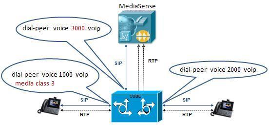
This information describes a sample configuration. CUBE may be deployed in multiple ways.Each MediaSense deployment for CUBE contains three dial-peers:
- Inbound dial-peer: In this example, the unique name is 1000
- Outbound dial-peer: In this example, the unique name is 2000
- Forking dial-peer: In this example, the unique name is 3000
Before you begin this procedure, obtain the details for these three dial-peers from your CUBE administrator.
Note
The order in witch you configure these three dial-peers is not important.Set up CUBE dial-peers for MediaSense deployments
ProcedureThis procedure provides an example of how to set up the three dial peers. The specific names and values used are for illustrative purposes only.
Caution
This procedure is not a substitute for the actual CUBE documentation. It is a tutorial to provide detailed information about configuring CUBE for MediaSense. See your CUBE documentation at http://www.cisco.com/go/cube for the latest information.
CUBE deployments log commands
Cisco Unified Border Element (CUBE) logs errors when calls fail, and it also applies a timestamp to debugging and log messages. The following table identifies some of the useful log commands.
Note
Millisecond timestamp provides a better indication of the timing of the various debugs events relative to each other. Do not use msec timestamp to prove performance issues, but to obtain relative information about when events occur.
Table 4 Useful log commands for CUBE deployments Command
Description
service timestamp debug datetime msec localtime show-timezone
Specifies the millisecond (msec) timestamp for various debug events.
service timestamps log datetime msec localtime show-timezone
Specifies the millisecond (msec) timestamp for various log events.
localtime logging buffered 1000000
Specifies the memory allocation for CUBE logins.
no logging rate-limit
Specifies that all log messages should be logged.
no logging console
Specifies that log messages should not be displayed on the console.
Access MediaSense Serviceability
ProcedureAfter you complete the post-installation setup of MediaSense Administration, you can sign in to MediaSense Serviceability.
Step 1 Access MediaSense Serviceability. You can access MediaSense Serviceability in one of the following ways:
- Enter the following URL in a MediaSense-supported web browser session, where servername is the IP address of the server on which you installed MediaSense: http://servername/oraservice
- From the Navigation drop-down menu in the upper-right corner of the Administration window, select Cisco MediaSense Serviceability and click Go.
Step 2 A security alert message may appear, prompting you to accept the self-signed security certificate. This security certificate is required for a secure connection to the server. Click the required button. This security message may not appear if you have already installed a security certificate.
The Authentication page is displayed.
Step 3 Enter the single sign-in username and password, and click Log in .
Note If you have already signed in to MediaSense, you can access MediaSense Serviceability without signing in again. The welcome page appears after you have successfully logged in. The welcome page displays the version number of the product as well as trademark, copyright, and encryption information.
MediaSense Serviceability
The MediaSense Serviceability menu bar contains the following options:
- Trace—Configure log and trace settings for MediaSense components. Once enabled, you can collect and view trace information using the Unified Real-Time Monitoring Tool (Unified RTMT).
- Tools—Contains options that allow you to access system tools such as Unified RTMT Plug-ins, manage network services, and control feature services.
- Help—Provides access to online help for MediaSense. After you are in the required administration interface, select one of the following options:
- To display documentation for a single window, click Help > This Page.
- To verify the version of the administration running on the server, click Help > About or click the About link in the upper-right corner of the window.
- To view the latest version of all documents for this release, click Help > Cisco.com. If you are connected to the external network, this link connects you to the home page for MediaSense (http://www.cisco.com/en/US/products/ps11389/tsd_products_support_series_home.html).
- To view the latest version of the troubleshooting tips for this release, click Help > Troubleshooting Tips . If you are connected to the external network, this link connects you to the Troubleshooting page for MediaSense (http://docwiki.cisco.com/wiki/Troubleshooting_Cisco_MediaSense).
- Trace setup
- Serviceability tools
- Access serviceability user interface for other servers in cluster
- Unified RTMT administration
Trace setup
This section provides information about using traces in MediaSense Serviceability Administration.
Trace files
A trace file is a log file that records activity from the MediaSense components. Trace files allow you obtain specific, detailed information about the system so you can troubleshoot problems. The MediaSense system can generate trace information for different services. The generated information is stored in a trace file. To help you control the size of a trace file, you can specify the services for which you want to collect information and the level of information that you want to collect.
Trace information is primarily used by developers to debug problems. Each MediaSense service can consist of several components. Each component can consist of multiple trace flags. You can enable or disable tracing for each component or for the required flags. Unlike logs, trace files are written only at one level. This section describes the trace configuration requirement for MediaSense Serviceability Administration.
Caution
If MediaSense Administration is unable to contact the MediaSense configuration service, it uses default trace settings. If the MediaSense configuration service is disabled or stopped, the trace configuration information is not displayed in the corresponding user interface pages. Similarly, if trace configuration is not available for any service, the user interface pages will not display any information for that service.Differences between tracing and logging:
- Tracing: trace flags are free from detailed, developer-oriented information that is not printed to the logs by default, but only when increased logging is enabled to debug problems.
- Logging: log messages are predefined, higher-level messages that are always printed to the logs and indicate everything for normal system behavior to severe error conditions.
- Trace log levels
- Trace flags
- Trace file location
- Set up trace file information
- Trace file interpretation
Trace log levels
Trace flag information is stored in the configuration database.
Log Levels identify the MediaSense message level (info and debug) to be generated for each service. The currently-enabled log levels for each service component are identified by a radio button (Log Level column) in the Trace Configuration screen. The currently-enabled trace flags are identified by a check mark (Enabled column) in the Trace Configuration screen.
Note
There is no log level or trace mask for the Perfmon agent network service.
Caution
Because the media service does not support dynamic trace-level change, you cannot create or view a trace file for this service. Trace flags for the media service are used only by TAC and are not available to end users.MediaSense log information is provided in the following output files:
- ORASERVICE-oraservice.<yyyy-MM-dd>T<HH-mm-ss.SSS>.startup.log: contains debug and info messages (see the MediaSense log levels table above for more information about debug and info message levels).
- Error-oraservice.<yyyy-MM-dd>T<HH-mm-ss.SSS>.startup.log: contains only system conditions.
Each of these files has a default maximum file size of 50 Megabytes (MB). The log file size and the number of files are not configurable.
Trace flags
Each service component has different logical divisions with corresponding trace flags. To ensure that a minimum level of logging information is captured whenever an issue occurs, a specific set of trace flags is enabled by default when MediaSense is installed. For the trace flags to take effect, you must set the log level for the corresponding component to DEBUG. Hence, the log level for most components is set to DEBUG by default when the MediaSense system is installed.
You can enable the entire component or certain trace flags within each component. You can also set different log level values (info or debug) for different MediaSense services in the same cluster.
MediaSense serviceability administration lists each trace flag within its MediaSense service component.
Caution
You cannot create a trace file for the media service because this service does not support dynamic trace-level changes.The list show the components that have their required trace flags enabled by default:
Trace file location
The trace file contains information about each service.
After configuring the information that you want to include in the trace files for each service, you can collect and view the trace files by using the Unified Communications Trace and Log Central option in the Unified Real-Time Monitoring Tool (Unified RTMT). Trace and Log Central is the Unified Communications component which manages and provides access to trace files. When the services start up (during the post-installation process), the trace and log files are visible in the RTMT Trace and Log Central section after you launch Unified RTMT.
See Cisco Unified Real-Time Monitoring Tool Administration Guide (http://www.cisco.com/en/US/products/sw/voicesw/ps556/prod_maintenance_guides_list.html) for detailed information.
Set up trace file information
Procedure
Caution
By default, trace flags are set for each component to collect the minimum amount of information in case an issue arises. These flags are selected based on their value in capturing the most information without impacting the performance of the system. In some cases, you may need to enable additional trace flags (usually under the direction of Cisco Support to collect more information in the logs for an issue). These additional trace flags may slow performance of the system. If that is the case, after the information is collected, disable these additional trace flags.To configure trace file information and to enable and disable trace flag settings, follow this procedure.
Step 1 From MediaSense Serviceability Administration select Trace > Configuration. The Trace Configuration web page opens displaying the configured trace flags along with the applicable trace flags for each service.
Step 2 For each service, select the required trace log levels and trace flags. Step 3 Click Save to generate the trace files per the configured settings. Alternately, click Reset to revert to the default settings for the selected service or click Cancel to revert to your previous settings.
Step 4 Retrieve the saved file from the corresponding trace file location.
Performance logging
Use the performance logging web page to configure thread traces and memory traces so that you can monitor the performance of MediaSense clusters.
From the performance logging web page, you can dump thread and memory traces for the following MediaSense services:
- API service
- Configuration service
- Call control service
- Storage management agent
- Administration
- Diagnostics
- Serviceability administration
- System service
- Perfmon agent
Each trace dump provides varied log information in different log files:
- The dump thread trace feature provides log information about all threads for each service (name, state, and stack) in the following four-part (.txt) file name format: diagnostic-threads.<process-id>.<service-id>.<time stamp>.txt
- The dump memory trace feature provides memory information for each service in the following four-part (.hprof) file name format: diagnostic-memory.<process-id>.<service-id>.<time stamp>.hprof
- The dump memory trace feature also provides heap information for each service in the following four-part (.txt) file name format: diagnostic-memory.<process-id>.<service-id>.<time stamp>.txt
When you dump trace information, the information for the selected service (thread or memory) is collected in the log folder for that service. You can then use the Unified Real Time Monitoring Tool (Unified RTMT) to download the log file.
Dump trace parameters
Procedure
Step 1 From MediaSense Serviceability Administration select Trace > Performance Logging. The performance logging web page opens displaying the configured trace flags along with the list of applicable services.
Step 2 Select the service for which you need to collect the trace parameters. Step 3 Click Dump Thread Trace to generate the thread trace files for the selected service. This dump option allows you to detect deadlocks and analyze whether a thread uses excessive resources or causes out-of-memory errors. Alternately, click Dump Memory Trace to generate the memory trace files for the selected service. This dump option allows you to find objects which use a large amount of memory in the Java Heap.
This creates the corresponding log files in the folder for the selected service.
Step 4 Retrieve the saved file from the corresponding trace file location using Unified RTMT.
Serviceability tools
To troubleshoot a problem, you may need to manage services in MediaSense Serviceability and in Unified Serviceability.
See the Cisco Unified Serviceability Guide at http://www.cisco.com/en/US/products/sw/voicesw/ps556/prod_maintenance_guides_list.html.
Control center network services
Control center network services are installed automatically.
After the installation, control center network services start automatically in each server in the cluster. You can stop these network services if necessary.
Note
- The local server time is displayed in the administration interface. This time cannot be configured.
- In MediaSense release 9.0(1) only, because SNMP is not supported, you cannot configure SNMP community strings in Unified Serviceability Administration. Configuring these strings will hang the host resources agent.
Manage network services
Procedure
Step 1 From the MediaSense Serviceability menu bar, click Tools and select Control Center - Network Services. Services that display in the Control Center - Network Services window do not start until you start each service.
The Control Center - Network Services web page displays the configurable MediaSense services along with the service status for the default server (the primary server in the cluster).
Caution Like other network services, the system service and serviceability administration are operational at startup. You cannot stop the system service or MediaSense serviceability administration from this web page. If the system service or serviceability administration goes down, no service control operations can take place. If you encounter any problem with the system service or serviceability administration, you can start or restart these services using the utils service command.
Step 2 To start, stop, or restart services, check the check box preceding the required service name. A check mark appears in the check box to indicate your selection.
Step 3 Click the Start, Stop, or Restart button to perform the required operation. A progress message appears in the status section (below the toolbar) to indicate task completion or s corresponding error message.
Note At any time, click Refresh to update the screen with the latest status of the services.
Control center feature services
MediaSense serviceability provides several options to control feature services.
Manage feature services
Procedure
Step 1 From the MediaSense Serviceability menu bar, click Tools and select Control Center - Feature Services . Services that display in the Control Center - Feature Services window do not start until you start each service.
The Control Center - Feature Services web page displays the configurable MediaSense services along with their status for the default server (the primary server in the cluster).
Step 2 To start, stop, or restart services, check the check box preceding the required service name. A check mark appears in the check box to indicate your selection.
Step 3 Click the Start, Stop, or Restart button to perform the required operation. A progress message appears in the status section (below the toolbar) to indicate task completion or a corresponding error message.
Note At any time, click Refresh to update the screen with the latest status.
Media service call control service or database service reactivation
Reactivating the media service, the call control service, or the database service results in the following consequences:
- The existing recordings before the restart will not be available after the reactivation.
- You can record new calls only after the service is reactivated.
Note
Reactivate or restart call control, database, and media services during off-peak hours to ensure minimum disruption to recordings in progress.Access serviceability user interface for other servers in cluster
Before You BeginProcedureThe MediaSense configuration service must be in the In service state in either the primary server or the secondary server so that the cluster details can be displayed in the Cluster Access web page.
Step 1 From the MediaSense Serviceability menu bar, click Tools and select MediaSense Cluster Access. The Cisco MediaSense Cluster Access web page displays the available links for each server in this cluster. Each server is identified as a primary server, a secondary server, or an expansion server. The corresponding link takes you to MediaSense serviceability administration for this server. You must sign in to one of these servers to continue.
Step 2 In the MediaSense Serviceability Administration Authentication window, enter the User ID and password. Select Sign in.
Unified RTMT administration
This section provides details specific to MediaSense for the Unified Real-Time Monitoring Tool (Unified RTMT). The Unified RTMT tool, which runs as a client-side application, uses HTTPS and TCP to monitor system performance and device status for MediaSense. Unified RTMT can connect directly to devices using HTTPS to troubleshoot system problems.
Even when Unified RTMT is not running as an application on your desktop, tasks such as performance monitoring updates continue on the server in the background.
Caution
The VLT plug-in is not available in MediaSense. The plug-in is not available because Cisco VLT does not support message files involving Session Initiation Protocol (SIP) calls.
Warning
You can monitor a maximum of 3000 processes and threads in a MediaSense system. The Maximum Number of Processes and Threads field is required by Unified CM in the Unified OS. This field specifies the maximum number of processes and threads running on the server. If the total number of processes and threads exceeds 3000, an alarm and corresponding alert are generated. See the Unified CM documentation (http://www.cisco.com/en/US/products/sw/voicesw/ps556/prod_maintenance_guides_list.html) for more information.
- Unified RTMT installation and setup
- Unified RTMT upgrade
- Unified RTMT multiple copy installations
- Server status monitoring
- Performance monitoring counters
- System condition and perfmon counter alerts
- Trace and log central Unified RTMT setup
- Perfmon agent and counters
Unified RTMT installation and setup
You can install Unified RTMT on a computer that is compatible with the MediaSense software. To install the Unified RTMT plug-in from MediaSense Administration, see Download the Unified RTMT plug-in.
Note
To obtain a complete list of supported hardware and software for MediaSense, see the Hardware & System Software Specification (Bill of Materials) for Cisco Unified Contact Center Enterprise at: http://www.cisco.com/en/US/products/sw/custcosw/ps1844/products_user_guide_list.html.Download the Unified RTMT plug-in
Procedure
Step 1 From the Cisco MediaSense Serviceability menu bar, click Tools and select RTMT Plugin Download. The Unified RTMT Plugin Download web page is displayed.
Step 2 To download the Unified RTMT Plugin executable to the preferred location on the client machine, click Download. Follow the download procedure to install Unified RTMT on your client.
Step 3 After the Unified RTMT welcome window appears, click Next. Step 4 To accept the license agreement, check the box next to I accept the terms of the license agreement ; then, click Next. Step 5 Choose the location where you want to install Unified RTMT. If you do not want to use the default location, click Browse and navigate to a different location. Click Next. Step 6 To begin the installation, click Next. The Setup Status window is displayed. Do not click Cancel.
Step 7 To complete the installation, click Finish.
Unified RTMT upgrade
Unified RTMT saves user preferences and downloaded module jar files locally on the client server. It also saves user-created profiles in the database. You can still access these items in Unified RTMT after you upgrade the tool.
Note
To ensure compatibility, you must upgrade Unified RTMT after you complete the MediaSense administration upgrade on all servers in the cluster.Unified RTMT multiple copy installations
You cannot install more than one copy of Unified RTMT on a server. That copy can monitor any Unified Communications product and any number of MediaSense clusters.
To monitor a product on a server in a different cluster, you must first log off the server before you can log on to the other server.
Server status monitoring
The Systems tab lists all critical services related to the system and the MediaSense tab defines all critical services related to MediaSense. These critical services are enabled when VOS starts.
Performance monitoring counters
Unified Communications provides performance monitoring (perfmon) counters that enable you to monitor MediaSense in real time. MediaSense maintains the values of its perfmon counters. Unified RTMT enables you to view the counter values.
See the Cisco Unified Real-Time Monitoring Tool Administration Guide (http://www.cisco.com/en/US/products/sw/voicesw/ps556/prod_maintenance_guides_list.html) for detailed information about the Unified RTMT user interface and its logs.
Unified RTMT for performance monitoring
The Unified RTMT tracks and displays current performance information and alerts for MediaSense. Unified RTMT is integrated with the MediaSense administration and serviceability software.
Unified RTMT enables you to monitor the performance of all servers in MediaSense clusters. You can also continuously monitor a set of pre-configured objects.
In addition, Unified RTMT:
- Sends pop-up or email alerts to system administrators when performance counter values exceed predefined thresholds.
- Saves and restores settings, such as counters being monitored, threshold settings, and alert notifications, so that you can customize troubleshooting tasks.
- Charts up to six Perfmon counter values so that you can compare them.
System condition and perfmon counter alerts
Unified RTMT displays both pre-configured alerts and custom alerts in Alert Central. Unified RTMT organizes the alerts under several tabs—System, Custom, and MediaSense. Although the System tab and Custom tab are the same as those tabs available in Unified CM, the MediaSense tab is specific to MediaSense.
In MediaSense, system conditions are used to interpret the working states of the system. Whenever an error or a critical situation arises that prevents the system from functioning at its maximum capacity, a system condition is raised to indicate the problem. When the problem is resolved, the system condition is cleared and the system returns to normal state. The system condition contains information about the problem and possible corrective actions to address the problem. The various MediaSense log messages can have a system condition which can be raised and cleared based on the log message.
System condition alerts and perfmon counter alerts for MediaSense are visible as individual alerts on the MediaSense tab in the Alert Central tool in Unified RTMT. Each alert description explains the system condition and possible actions to resolve it.
Items in red indicate that an alert has been raised. If the alert is cleared, the timestamp is updated by the alert. The timestamp remains red so that it is visible when the administrator signs in. In the Safe region, the Yes indicates that the alert was raised under normal conditions, and the NA indicates that the safe range field does not apply to the system condition.
The following table lists the system condition alerts (prepended by SC_) and perfmon counter alerts (prepended by PC_) and their corresponding descriptions within each MediaSense service class object.
Table 5 System condition and perfmon counter alerts Service
Alert
SC_ = system condition alert
PC_ = perfmon counter alert
Description
Recommended action
Tomcat (config service)
SC_ConfigLostContactWithDB
The configuration service lost contact with its database service.
Check the MediaSense database service. Restart it if necessary.
SC_ConfigurationOOS
The configuration service is out of service.
Check the MediaSense database service. Restart it if necessary.
SC_ConfigurationLostContact WithAXL
The configuration service lost contact with its Unified CM AXL server.
Check the Unified CM AXL configuration. Modify or restart it if necessary.
MediaSense call control service
SC_RecordingLatencyWarning
Recording start latency exceeds warning threshold.
Check the media server. Restart it if necessary.
SC_CallControlOOS
Call control service is out of service.
Check the call control server. Restart it if necessary.
SC_CallControlLostContact WithAPI
Call control service lost contact with API Service.
Check the API server. Restart it if necessary.
SC_CallControlLostContact WithMedia
Call control service lost contact with media Service.
Check the Media server. Restart if necessary.
SC_CallControlLoadCritical
Call load exceeds critical threshold.
Reduce the load by decreasing the number of phones that are configured for recording in a given cluster or install an additional MediaSense server.
PC_CallControlMaximumHeap Memory ThresholdReached
Safeguards the MediaSense system from running out of memory. If this counter crosses the 128 MB memory threshold, the system triggers an alert.
Reduce the load by decreasing the number of phones that are configured for recording in a given cluster or install an additional MediaSense server.
Tomcat API service
SC_APILostContactWith Database
API Service lost contact with its database service.
Check the MediaSense database service. Restart it if necessary.
SC_APIServiceOOS
API Service is out of service.
Check if SC_ORA_API_LOST_ CONTACT_WITH_ DATABASE has also been raised. If yes, then check the MediaSense database service. Restart it if necessary.
If that does not work, restart Tomcat (API Service).
If SC_ORA_API_LOST_ CONTACT_WITH_ DATABASE has not been raised, then restart Tomcat (API Service).
MediaSense system service
SC_SystemServiceOOS
The system service is out of service.
Check system service. Restart it if necessary.
MediaSense database service
SC_DatabaseServiceOOS
database service is out of service.
Check the database service. Restart it if necessary.
MediaSense storage management agent
SC_DiskSpaceWarning
Available media storage level is low.
Consider deleting old recordings.
SC_DiskSpaceCritical
Available media storage level is critical. The system may fail to process new requests.
Delete old recordings to free up storage space.
SC_DiskSpaceEmergency
No media storage space is available. This server is not functional.
Delete old recordings to free up storage space.
AMC service and Unified CM setup
To support the Unified RTMT client, a number of services must be active and running on the MediaSense server. AMC service is one such service. It starts up automatically after the Unified RTMT installation and allows the Unified RTMT client to retrieve real-time information from the MediaSense server. The AMC service, the Alert Manager, and the collector service enable Unified RTMT to retrieve real-time information from the server or from all servers in the MediaSense cluster.
To view the state of the AMC service, navigate to Unified CM Administration on MediaSense server and choose System > Service Parameters. Then, choose the required server and select the Cisco AMC service . For more information about the AMC Service, see the Cisco Unified Real-Time Monitoring Tool Administration Guide (http://www.cisco.com/en/US/products/sw/voicesw/ps556/prod_maintenance_guides_list.html).
Caution
If for any reason, the primary MediaSense server shuts down or is in a failed state, and the secondary MediaSense server continues to function in the normal state. If you launch the Unified RTMT client at this time, the MediaSense tab in the Alert Central window may remain blank and display Error polling alert \ status. AMC service is down. in the status pane. Similarly, the System Summary pane may display HTTP request failed. Web Server unreachable. for the same issue. To work around this issue, configure the secondary Cisco AMC Service in the primary Cisco MediaSense server.
Note
Be sure to make the following change in the primary Cisco MediaSense server first.Navigate to Unified CM Administration (in the primary Cisco MediaSense server). Choose System > Service Parameters. Then, select the secondary MediaSense server from the drop-down list, and finally select Cisco AMC Service. In the resulting Service Parameter Configuration web page, select the secondary MediaSense server from the drop-down list next to the Failover Collector field. After you configure the AMC Service for the secondary MediaSense server, the secondary server takes over when the primary MediaSense server goes down, and Unified RTMT continues to display alert names under Alert Central.
Note
You can access Unified CM Administration on the MediaSense server by providing the following URL format in a browser window: http://<MediaSenseServer-ip-address>/ccmadmin.Trace and log central Unified RTMT setup
The trace and log central feature in Unified RTMT enables you to configure on-demand trace collection for a specific date range or for an absolute time. You can collect trace files that contain the search criteria that you specify. You can also save the trace collection criteria for later use, schedule one recurring trace collection and download the trace files to a SFTP or FTP server on your network, or collect a crash dump file. After you collect the files, you can view them in the appropriate viewer within Unified RTMT. You can also view traces on the server without downloading the trace files by using the remote browse feature. You can open the trace files by either selecting the internal viewer that is provided with Unified RTMT or selecting another appropriate application as an external viewer.
Note
To use the trace and log central feature in Unified RTMT, make sure that Unified RTMT can directly access all servers in the cluster without using Network Access Translation (NAT).File collection
The collect files tool allows you to specify the required MediaSense services and application in the Select MediaSense Services/Application tab, which is part of the collect files wizard. After you specify the required MediaSense services, continue to proceed as you would for the System Service/Application. You can collect trace files that contain search criteria that you specify and save the trace collection criteria for later use.
Crash dump collection
Unified Serviceability stores the logs for the version of application that you are logged in to in the active partition and stores the logs for the other version (if installed) in the inactive folder.
Remote browse folder names and services
To view .log or .out files, use one of the following applications:
- Right-click the required file and select Open to view it in the Default Viewer.
- Right-click on the required file and select Open with to view all available applications with which to view these files.
Caution
MediaSense does not support the QRT Viewer.The remote browse folder name (log and trace file folder name) for each MediaSense service is shown in the second column of the following table.
MediaSense service or agent name
Remote browse folder name
Call control service
callcontrol
Media service
media
API service
ora
Configuration service
oraconfiguration
Database service
oradb
SM agent
storagemanagementagent
MediaSense administration
oraadmin
Serviceability administration
oraservice
System service
systemservice
Perfmon agent
perfmonagent
Diagnostics
diagnostics
Caution
MediaSense provides some log files in a GZIP format. However, in Unified RTMT, the trace and log central remote browse feature does not display these files by default. You can add the appropriate application or download and save the .gzip file and view it directly from the downloaded location.Perfmon agent and counters
The perfmon agent monitors performance for MediaSense. It has no separate user interface. It operates seamlessly within MediaSense serviceability administration. Like other network services, the perfmon agent is operational at startup.
The perfmon agent retrieves its performance monitoring counter values from JMX MBeans and writes these values to the Unified Communications Manager database.
The perfmon agent also logs the perfmon counter values in the Unified RTMT. You can use Unified RTMT to view the most recent counter values and descriptions and to identify the objects that are available for system monitoring.
The following table classifies, names, and describes perfmon counters. The first column shows perfmon counters by class and name. The second column contains the counter descriptions. Note that the class objects provide process or time-usage information in percentages.
Counter class and name
Counter description
Class: MediaSense call control service
Recording sessions counters
Heap memory usage
Sends an alert when its value exceeds 128 MB of memory (to help keep MediaSense from running out of memory).
Number of active sessions
The number of active recording sessions.
Number of recorded sessions without errors
The number of recorded sessions completed without errors.
Number of recorded sessions with errors
The number of recorded sessions completed with errors.
Recording setup time
Mean setup delay
The average delay (in milliseconds) between the initial receipt of the SIP Invite from Unified CM and the SIP response to the Unified CM rolling window time.
Max setup delay
The maximum delay (in milliseconds) between the initial receipt of the SIP Invite from Unified CM and the SIP response to the Unified CM rolling window time.
Stream dialog API (used by video greeting in Unity Connection)
Started dialogs
The total number of stream dialogs started.
Start record API requests
The total number of successfully started stream dialog start recording requests.
Start playback API requests
The total number of successfully started stream dialog start playback requests.
Rejected dialogs due to busy
The total number of stream dialog start requests that returned BUSY.
Mean start record time
The average amount of time (in milliseconds) taken to successfully start a recording operation.
Mean start playback time
The average amount of time (in milliseconds) taken to successfully start a play operation.
Mean dialog time
The average amount of time (in milliseconds) a stream dialog was active.
Max start record time
The maximum amount of time (in milliseconds) taken to successfully start a recording operation.
Max start playback time
The maximum amount of time (in milliseconds) taken to successfully start a play operation.
Max dialog time
The maximum amount of time (in milliseconds) a stream dialog was active.
Completed dialogs
The total number of stream dialogs completed.
Average active dialogs on busy
The average number of stream dialogs (rounded down to nearest integer) that were active when a stream dialog start request returned BUSY.
Class: MediaSense media service
Number of active playbacks
The number of outgoing RTSP sessions.
Number of live monitored calls
The number of ports used for live-monitored calls. One live-monitored call uses two ports in most cases.
Class: MediaSense configuration service
Authentication request processing: average latency
The average latency for processing an authentication request.
Authentication request processing: max latency
The maximum latency for processing an authentication request.
Total requests
For Cisco use only.
Total failures
The total number of request failures encountered by the MediaSense configuration service.
Class: MediaSense API service
Mean query response time
The average query response time in the last hour.
Max query response time
The maximum query response time in the last hour.
Total number of responses
The total number of successful and unsuccessful responses.
Total number of requests
The total number of requests received and serviced by the API Service.
Avg time per request
The average time for each request received and serviced by the Call Control Service in the last hour.
Max time per request
The maximum time for each request received and serviced by the Call Control Service in the last hour.
Max number of concurrent requests
The maximum number of concurrent requests received and serviced by the Call Control Service in the last hour.
Total number of concurrent requests in progress
The total number of concurrent requests in progress in the last hour.
Class: MediaSense SM agent
Common partition usage
The percentage of common partition disk usage.
Media # partition usage
The percentage of disk usage of each media partition.
Audio recording ports in use
The number of audio ports currently in use for recording.
Video recording ports in use
The number of video ports currently in use for recording.
Available audio ports
The number of audio ports available.
Available video ports
The number of video ports available.
Total audio ports in use
The number of audio ports currently in use.
Total video ports in use
The number of video ports currently in use.
Total RTSP playback requests
The number of RTSP playback requests.
Total RTSP playback requests last 5 min.
The number of RTSP playback requests in the last 5 minutes.
Rejected RTSP playback requests
The number of rejected RTSP playback requests
Rejected RTSP playback requests last 5 min.
The number of rejected RTSP playback requests in the last 5 minutes.
Total RTSP monitoring requests
The number of RTSP monitoring requests
Total RTSP monitoring requests last 5 min.
The number of RTSP monitoring requests in the last 5 minutes.
Rejected RTSP monitoring requests
The number of rejected RTSP monitoring requests.
Rejected RTSP monitoring requests last 5 min.
The number of rejected RTSP monitoring requests in the last 5 minutes.
Total raw download requests
The number of raw download requests
Total raw download requests last 5 min.
The number of raw download requests in the last in 5 minutes.
Rejected raw download requests
The number of rejected raw download requests.
Rejected raw download requests last 5 min.
The number of rejected raw download requests in the last 5 minutes.
Total convert requests
The number of convert requests.
Total convert requests last 5 min.
The number of convert requests in the last 5 minutes.
Rejected convert requests
The number of rejected convert requests.
Rejected convert requests last 5 min.
The number of rejected convert requests in the last 5 minutes.
Class: MediaSense database service
This class has no perfmon counters.
Class: MediaSense system service
This class has no perfmon counters.
Class: MediaSense diagnostics
This class has no perfmon counters.
Class: MediaSense administration
This class has no perfmon counters.
Class: MediaSense serviceability administration
This class has no perfmon counters.
Server IP address changes
Use the following procedures to change the IP address of any fully installed server in a MediaSense cluster (meaning that the setup wizard must have finished running on the server for which the IP address is being changed).
Note
Do not attempt to change the IP address of any server while another server is being installed. Use these procedures only on a fully installed server (do not attempt to use these procedures if an installation has failed or while installation is in progress on any server in the cluster.
- Prepare system for IP address change
- Change IP address of primary server
- Change IP address of secondary server
- Change IP address of expansion server
- Change multiple IP addresses in a MediaSense cluster
Prepare system for IP address change
ProcedurePerform the following tasks to ensure that your system is prepared for a successful IP address change.
Step 1 List all servers in the cluster and note whether the servers are defined by using IP addresses or by host names.
- If you are verifying the list from the MediaSense Administration interface on the primary server, navigate to System > MediaSense Server Configuration. A list of all servers in the cluster is displayed.
- If you are verifying the list from the command line interface (CLI) on the primary server, issue the Show Network Cluster command.
Step 2 Save a list of the hostname and IP address of each server in the cluster. Step 3 Ensure that all servers in the cluster are running and available by checking for any active ServerDown alerts. You can check from the Unified RTMT interface or from the CLI on the primary server.
Step 4 Check the database replication status on all MediaSense servers in the cluster to ensure that all servers are replicating database changes successfully. You can check by using the Unified RTMT interface or a CLI command.
- Unified RTMT interface: access the database summary and inspect the replication status.
- CLI: Enter the command shown in the following example:
show perf query class "Number of Replicates Created and State of Replication"
==>query class:
- Perf class (Number of Replicates Created and State of Replication)
has instances and values:
ReplicateCount  -> Number of Replicates Created   = 344
ReplicateCount  -> Replicate_State                = 2
Be aware that the Replicate_State object shows a value of 2 in this case.
The following list shows the possible values for Replicate_State:
- 0 = Replication Not Started. Either no subscribers exist, or the Database Layer Monitor service has not been running since subscriber installed.
- 1 = Replicates have been created, but their count is incorrect.
- 2 = Replication is good.
- 3 = Replication is bad in the cluster.
- 4 = Replication setup did not succeed.
Step 5 To check for network connectivity and DNS server configuration, enter the utils diagnose module validate_network command.
Example:utils diagnose module validate_network Log file: /var/log/active/platform/log/diag1.log Starting diagnostic test(s) =========================== test - validate_network: Passed Diagnostics Completed
Change IP address of primary server
Procedure
Warning
Using this procedure disrupts all services. Be sure to use it only during a scheduled downtime.Use this procedure to change the IP address of a MediaSense primary server if your cluster servers are defined using host names. To successfully change the IP address, you must complete all steps in this procedure.
Step 1 Review and address the instructions listed in Prepare system for IP address change before changing the IP address on any MediaSense server. Step 2 Verify that the DNS change propagates to other servers by using the utils network host and show tech network hosts CLI commands on all servers in the cluster.
Example:utils network host mcs-sec Hostname mcs-sec resolves to 10.10.10.136 show tech network hosts -------------------- show platform network -------------------- /etc/hosts File: #This file was generated by the /etc/hosts cluster manager. #It is automatically updated as nodes are added, changed, removed from the cluster. 127.0.0.1 localhost 1 10.10.10.92 mcs-pri.cisco.com mcs-pri 2 10.10.10.93 mcs-sec.cisco.com mcs-sec 3 10.10.10.137 mcs-exp1.cisco.com mcs-exp1Step 3 From the primary server, issue the set network cluster server ip command to update the MediaSense cluster configuration with the primary server’s new IP address.
Example:set network cluster server ip 10.10.10.92 10.10.10.135 Setting server ip 10.10.10.92 10.10.10.135 SuccessfulStep 4 Verify the interim cluster configuration by issuing the show network cluster command.
Example:show network cluster 1 10.10.10.135 mcs-pri Primary not authenticated or updated on server 2 10.10.10.93 mcs-sec.cisco.com mcs-sec Secondary authenticated using TCP since Mon Sep 12 12:33:16 2011 3 10.10.10.137 mcs-exp1.cisco.com mcs-exp1 Expansion authenticated using TCP since Mon Sep 12 12:33:06 2011 - 10.194.118.92 mcs-pri.cisco.com mcs-pri Primary authenticatedStep 5 Point every server in the cluster to the new primary’s IP address by issuing the set network cluster primary ip command from each server in the MediaSense cluster, including the primary server:
Example:set network cluster primary ip 10.10.10.135 Setting primary ip to 10.10.10.135 SuccessfulStep 6 Ensure that the IP address change is replicated to the secondary and expansion servers database by entering the run sql select name,nodeid from ProcessNode command on all servers in the cluster. The following example shows the command output:
Example:run sql select name,nodeid from ProcessNode name nodeid ================== ====== EnterpriseWideData 1 mcs-pri 2 mcs-sec 3 mcs-exp1 4Step 7 If you are moving the primary server to a different subnet that requires a new default gateway address, change the default gateway by issuing the set network gateway command from the primary server:
Example:set network gateway 10.3.90.2 *** W A R N I N G *** This will cause the system to temporarily lose network connectivity Do you want to continue ? Enter "yes" to continue or any other key to abort yes executing...
Note If you change the default gateway, you may also need to change the subnet mask. See the Unified OS documentation for further details. Step 8 From the primary server, issue the set network ip eth0 command to reset the network adapter to the new IP address.
Example:set network ip eth0 <server new ip> <address mask> <gw> set network ip eth0 10.194.118.137.92 255.255.255.0 10.194.118.1 *** W A R N I N G *** You must first change the IP Address using the <set network cluster server> CLI command BEFORE changing it here or call recording will fail. This will cause the system to restart. ======================================================= Note: To recognize the new IP address all nodes within the cluster must be manually rebooted. ======================================================= Continue (y/n)? yThis command changes the IP address and re-boots the primary server.
Step 9 Type Yes and press Enter. Step 10 To update the local name resolution files, reboot all other servers in the cluster . Include hosts, rhosts, sqlhosts, and services.
Note Server restart ensures the proper update and service-restart sequence for the IP address changes to take effect. Step 11 Verify that the DNS change propagates to other servers by using the utils network host and show tech network hosts commands on all servers in this cluster.
Example:utils network host mcs-pri Hostname mcs-pri resolves to 10.10.10.135 show tech network hosts -------------------- show platform network -------------------- /etc/hosts File: #This file was generated by the /etc/hosts cluster manager. #It is automatically updated as nodes are added, changed, removed from the cluster. 127.0.0.1 localhost 1 10.10.10.135 mcs-pri.cisco.com mcs-pri 2 10.10.10.93 mcs-sec.cisco.com mcs-sec 3 10.10.10.137 mcs-exp1.cisco.com mcs-exp1Step 12 Verify the cluster configuration by issuing the show network cluster command.
Example:show network cluster 1 10.10.10.135 mcs-pri.cisco.com mcs-pri Primary authenticated using TCP since Mon Sep 12 14:43:59 2011 2 10.10.10.93 mcs-sec.cisco.com mcs-sec Secondary authenticated 3 10.10.10.137 mcs-exp1.cisco.com mcs-exp1 Expansion authenticated using TCP since Mon Sep 12 14:44:05 2011
Caution It may take some time for the cluster to synchronize the new IP address information. During this time, the output for this command may show partial or incomplete information.
Change IP address of secondary server
Procedure
Warning
This procedure disrupts all services. Be sure to make any changes during a scheduled downtime.Use this procedure to change the IP address of a MediaSense secondary server if your cluster servers are defined using host names. To successfully change the IP address, you must complete all steps in this procedure.
Step 1 Review and address the instructions listed in Prepare system for IP address change before changing the IP address on any MediaSense server. Step 2 From the primary server, issue the set network cluster server command to update the MediaSense cluster configuration with the secondary server’s new IP address.
Example:set network cluster server ip 10.10.10.93 10.10.10.136 Setting server ip 10.10.10.93 10.10.10.136 Successful lStep 3 Verify the interim cluster configuration by issuing the show network cluster command.
Example:show network cluster 1 10.10.10.135 mcs-pri.cisco.com mcs-pri Primary authenticated using TCP since Mon Sep 12 12:53:16 2011 2 10.10.10.136 mcs-sec Secondary not authenticated or updated on server 3 10.10.10.137 mcs-exp1.cisco.com mcs-exp1 Expansion authenticated using TCP since Mon Sep 12 12:53:06 2011 - 10.194.118.93 mcs-sec.cisco.com mcs-sec Secondary authenticatedStep 4 Point every server in the cluster to the new secondary server IP address by issuing the set network cluster secondary ip command:
Example:set network cluster secondary ip 10.10.10.136 Setting secondary ip to 10.10.10.136 SuccessfulStep 5 If you are moving the secondary server to a different subnet that requires a new default gateway address, change the default gateway by issuing the set network gateway command from the secondary server:
Example:set network gateway 10.3.90.2 *** W A R N I N G *** This will cause the system to temporarily lose network connectivity Do you want to continue ? Enter "yes" to continue or any other key to abort yes executing...Step 6 Type Yes and press Enter. Step 7 Ensure that the IP address change is replicated to the secondary and expansion server databases by entering the run sql select name,nodeid from ProcessNode command on all servers in the cluster. The following example shows the command output:
Example:run sql select name,nodeid from ProcessNode name nodeid ================== ====== EnterpriseWideData 1 mcs-pri 2 mcs-sec 3 mcs-exp1 4Step 8 From the secondary server, issue the set network ip eth0 <server new ip> <address mask> <gw> command to set the network adapter to the new IP address.
Example:set network ip eth0 10.194.118.137 255.255.255.0 10.194.118.1 *** W A R N I N G *** You must first change the IP Address using the <set network cluster server> CLI command BEFORE changing it here or call recording will fail. This will cause the system to restart ======================================================= Note: To recognize the new IP address all nodes within the cluster will have to be manually rebooted. ======================================================= Continue (y/n)? yStep 9 Re-boot all servers in the MediaSense cluster to update the local name resolution files. Include the hosts, rhosts, sqlhosts, and services.
Note Restarting the server ensures that changes occur in proper order for the update and service-restart sequence for the IP address. Step 10 Verify that the DNS change propagates to other servers by using the utils network host command and the show tech network hosts command on all servers in this cluster.
Example:utils network host mcs-sec Hostname mcs-sec resolves to 10.10.10.136 show tech network hosts -------------------- show platform network -------------------- /etc/hosts File: #This file was generated by the /etc/hosts cluster manager. #It is automatically updated as nodes are added, changed, removed from the cluster. 127.0.0.1 localhost 1 10.10.10.135 mcs-pri.cisco.com mcs-pri 2 10.10.10.136 mcs-sec.cisco.com mcs-sec 3 10.10.10.137 mcs-exp1.cisco.com mcs-exp1Step 11 Verify the interim cluster configuration by issuing the show network cluster command.
Example:1 10.10.10.135 mcs-pri.cisco.com mcs-pri Primary authenticated using TCP since Mon Sep 12 14:43:59 2011 2 10.10.10.136 mcs-sec.cisco.com mcs-sec Secondary authenticated 3 10.10.10.137 mcs-exp1.cisco.com mcs-exp1 Expansion authenticated using TCP since Mon Sep 12 14:44:05 2011
Change IP address of expansion server
Procedure
Warning
This procedure disrupts all services. Make any changes only during a scheduled downtime.If your cluster servers are defined using host names, use this procedure to change the IP address of any expansion servers. To successfully change the IP address, you must complete all steps in this procedure.
Step 1 Review and address the instructions listed in Prepare system for IP address change before changing the IP address on any server. Step 2 From the CLI of the primary server, issue the set network cluster server ip command to update the cluster configuration with the new IP address of the expansion server.
Example:set network cluster server ip 10.10.10.100 10.10.10.137 Setting server ip 10.10.10.100 10.10.10.137 SuccessfulStep 3 Verify the interim cluster configuration by issuing the show network cluster command.
Example:show network cluster 1 10.10.10.92 mcs-pri.cisco.com mcs-pri Primary authenticated 2 10.10.10.93 mcs-sec.cisco.com mcs-sec Secondary authenticated using TCP since Fri Sep 9 08:52:50 2011 3 10.10.10.137 mcs-exp1 Expansion not authenticated or updated on server - 10.10.10.100 mcs-exp1.cisco.com mcs-exp1 Expansion authenticated using TCP since Fri Sep 9 11:40:34 2011Step 4 Ensure that the IP address change is replicated to the secondary and expansion server databases by issuing the run sql select name,nodeid from ProcessNode command on all servers in the cluster. The following example shows the command output:
Example:run sql select name, nodeid from ProcessNode name nodeid ================== ====== EnterpriseWideData 1 mcs-pri 2 mcs-sec 3 mcs-exp1 4Step 5 If you are moving the expansion server to a different subnet that requires a new default gateway address, change the default gateway by issuing the set network gateway command from the expansion server:
Example:set network gateway 10.3.90.2 *** W A R N I N G *** This will cause the system to temporarily lose network connectivity Do you want to continue ? Enter "yes" to continue or any other key to abort yes executing...Step 6 From the expansion server, issue the set network ip eth0 <server new ip> <address mask> <gw> command to change the IP address of the expansion server.
Example:set network ip eth0 10.194.118.137 255.255.255.0 10.194.118.1 *** W A R N I N G *** You must first change the IP Address using the <set network cluster server> CLI command BEFORE changing it here or call recording will fail. This will cause the system to restart ======================================================= Note: To recognize the new IP address all nodes within the cluster will have to be manually rebooted. ======================================================= Continue (y/n)? yThis command changes the IP address and re-boots the expansion server.
Step 7 Type Yes and press Enter. Step 8 To update the local name resolution files, reboot all other servers in the cluster. Include all hosts, rhosts, sqlhosts, and services.
Note Restarting the server ensures the proper update and service-restart sequence for the IP address changes to take effect. Step 9 Verify that the DNS change propagates to other servers by using the utils network host and show tech network hosts commands on all servers in this cluster.
Example:utils network host mcs-exp1 Hostname mcs-exp1 resolves to 10.10.10.137 show tech network hosts -------------------- show platform network -------------------- /etc/hosts File: #This file was generated by the /etc/hosts cluster manager. #It is automatically updated as nodes are added, changed, removed from the cluster. 127.0.0.1 localhost 1 10.10.10.92 mcs-pri.cisco.com mcs-pri 2 10.10.10.93 mcs-sec.cisco.com mcs-sec 3 10.10.10.137 mcs-exp1.cisco.com mcs-exp1Step 10 Verify the cluster configuration by issuing the show network cluster command.
Example:show network cluster 1 10.10.10.92 mcs-pri.cisco.com mcs-pri Primary authenticated 2 10.10.10.93 mcs-sec.cisco.com mcs-sec Secondary authenticated using TCP since Mon Sep 12 12:33:16 2011 3 10.10.10.137 mcs-exp1.cisco.com mcs-exp1 Expansion authenticated using TCP since Mon Sep 12 12:33:06 2011
Change multiple IP addresses in a MediaSense cluster
ProcedureUse this procedure to sequentially change the IP addresses for multiple MediaSense servers. If you use this procedure, you need to issue a series of commands sequentially and reboot only once. To successfully change the IP address for all servers in a cluster, you must complete all steps in this procedure.
Note
This example procedure is written for a three-server cluster. As long as you change the IP addresses on one server at a time, you can modify this procedure for four-server or five-server clusters.
Caution
Change an IP address on only one server at a time. Changing an IP address on more than one server at the same time may cause .hosts files and .sqlhosts files to become out-of-sync.
Warning
Make changes only during a scheduled downtime. Changing IP addresses disrupts all MediaSense services.
Step 1 Review the instructions in Preparing for an IP Address Change before changing the IP address on any MediaSense server. Step 2 From the primary server, issue the following commands:
Example:set network cluster server ip <primary current ip> <primary new ip> set network cluster server ip <secondary current ip> <secondary new ip> set network cluster server ip <expansion current ip> <expansion new ip> set network cluster primary ip <primary new ip> set network cluster secondary ip <secondary new ip>Step 3 From the secondary server, issue the following commands:
Example:set network cluster primary ip <primary new ip> set network cluster secondary ip <secondary new ip>Step 4 From the expansion server, issue the following commands:
Example:set network cluster primary ip <primary new ip> set network cluster secondary ip <secondary new ip>Step 5 From the primary server, issue the following commands:
Example:run sql select name,nodeid from ProcessNodeStep 6 From the secondary server, issue the following commands:
Example:run sql select name,nodeid from ProcessNodeStep 7 From the expansion server, issue the following commands:
Example:run sql select name,nodeid from ProcessNodeStep 8 From the primary server, issue the following commands:
Example:set network gateway (if required) set network ip eth0 <primary new ip> <address mask> <gw>Step 9 From the secondary server, issue the following commands:
Example:set network gateway (if required) set network ip eth0 <secondary new ip> <address mask> <gw>Step 10 From the expansion server, issue the following commands:
Example:set network gateway (if required) set network ip eth0 <expansion new ip> <address mask> <gw>Step 11 From each server in the MediaSense cluster, issue the following commands to verify the cluster configuration.
Example:utils network host show tech network hosts show network cluster
MediaSense command line interface (CLI) commands
MediaSense Administration is enabled for sign-in at the completion of the installation and is the primary interface for administering, configuring, and maintaining MediaSense. If MediaSense Administration is not accessible for any reason, you can use the CLI commands specified in this chapter to perform certain tasks.
In the command syntax descriptions:
- Bold is used for the base command.
- Italics are used for mandatory parameters when the syntax includes them.
- [brackets] are used for options when the syntax includes them.
MediaSense does not support any Platform CLI commands that are not specifically listed in this document.
Utils commands
The section provides details about the MediaSense-specific utils commands.
utils media recording_sessions
The utils media recording_sessions file fileName command generates an html file with a detailed list of the last 100 recording sessions processed by this MediaSense server. Confirm that the MediaSense call control service is running for before you execute this command. The file is saved to the platform/cli/ folder and can be downloaded using the file get activelog platform/cli/fileName command.
Command: utils media recording_sessions file fileName
Details:
- file is a mandatory parameter that outputs the information to a file.
- fileName is a mandatory parameter that defines the name of the .html file.
- When you issue this command, you get the following response: MediaSense Call Control Service Recording sessions saved to platform/cli/<filename>.html You can now download it using: file get activelog platform/cli/<filename>.html You can then retrieve the file from that directory and save it to a location of your choice.
Example:
utils service
Purpose: Lists, starts, stops, or restarts each of the MediaSense services.
Command: utils service operation service_name
Details:
- operation specifies the type of operation to be performed by this command: Valid operations include:
- service_name specifies the name of the MediaSense service for which you require the specified operation. Valid services include:
Examples:
utils system maintenance
The command utils system maintenance operation enables or disables maintenance mode on MediaSense or displays the MediaSense maintenance mode status. While it is in maintenance mode, MediaSense cannot process any recording or API requests.
MediaSense re-boots when it enters maintenance mode. Any streaming activities end abruptly. Any active recordings end in a CLOSED_ERROR state. MediaSense re-boots again when maintenance mode is disabled and it re-enters normal mode.
Command: utils system maintenance operation
Details: operation specifies what the command does.
Valid operations include:
Examples:
Run commands
The section provides details about the MediaSense-specific run commands.
run db_reset_replication
Use this command to begin the process to manually reset replication for the entire MediaSense database. After the reset process is complete, this command returns a message with the status of the reset. You may need to use this command if the primary server fails within a multi-node cluster.
Note
In a multi-server deployment, you can run this command only on the secondary server.Command: run db_reset_replication
Details: This command has no options.
Example:
run db_reset_replicationrun db_synchronization
Use this command to compare the databases in the primary and secondary servers to ensure that the databases are synchronized.
Note
In a multi-server deployment, you can run this command only on the secondary server.Command: run db_synchronization database_name
Details:
- database_name specifies the type of operation to be performed by this command. The valid database names are:
Examples:
Set network commands
The section provides details about the MediaSense-specific set network commands.
- set network cluster server ip
- set network cluster primary ip
- set network cluster secondary ip
- set network ip eth0
set network cluster server ip
This command updates the MediaSense cluster configuration with the new IP address of a specific server. It does not change the IP address of the server itself. Issue this command on the primary MediaSense server only. Issuing this command on any other server results in an error.
Caution
This command may impact the synchronization of MediaSense services. Issue this command only as a part of the IP address change procedure. The MediaSense services may not be functional until the IP address change procedure is completed.
Note
This command requires the Configuration Service to be reachable and running on the primary server.You have three options to issue this command. In each case, the CLI reports a success or error as applicable.
- With no arguments: If you issue this command without any arguments, the CLI displays the list of servers. Select the server to be changed by entering the required number from the list index. (At this point, you can also quit by typing q.) You are then prompted to enter the new IP address of the server.
- With one argument: Provide the current IP address or the hostname of the server to be changed. The CLI prompts you to enter the new IP address of the server.
- With both arguments: Provide the current IP address or the hostname of the server to be changed and then provide the new IP address of the server.
Command: set network cluster server ip current_host new_ip
Details:
- current_host is the IP address or hostname of the server to be changed
- new_ip is the new IP address for the server
Examples:
set network cluster primary ip
This command configures the primary server IP address mapping in a given server.
Caution
This command may impact the synchronization of MediaSense services. Issue this command only as a part of the IP address change procedure. The MediaSense services may not function until the IP address change procedure is completed.Command: set network cluster primary ip new_ip
Detail: new_ip is the new IP address for the primary server
Example:
set network cluster primary ip 9.9.9.9
Setting primary ip to 9.9.9.9
Successful
set network cluster secondary ip
This command configures the secondary server IP address mapping in a given server.
Caution
This command may impact the synchronization of MediaSense services. Issue this command only as a part of the IP address change procedure. The MediaSense services may not function until the IP address change procedure is completed.Command: set network cluster secondary ip new_ip
Details: new_ip is the new IP address for the secondary server
Example:
set network cluster secondary ip 9.9.9.9
Setting secondary ip to 9.9.9.9
Successful
set network ip eth0
This command sets the IP address for Ethernet interface 0. You cannot configure Ethernet interface 1.
The system asks whether you want to continue to execute this command.
Caution
If you continue, this command causes the system to restart.
Caution
This command may impact the synchronization of MediaSense services. Issue this command only as part of the IP address change procedure. The MediaSense services may not function until the IP address change procedure is completed.Command: set network ip eth0 server new ip address mask gw
Details:
- eth0 specifies Ethernet interface 0.
- iserver new ip specifies the new IP address that you want to assign.
- address mask specifies the IP mask that you want to assign.
- gw specifies the gateway
Example:
set network ip eth0 10.194.118.137 255.255.255.0 10.194.118.1

***   W A R N I N G   ***
You must first change the IP Address using the
<set network cluster server> CLI command BEFORE
changing it here or call recording will fail.
This will cause the system to restart.
=======================================================
Note: To recognize the new IP address all nodes within
the cluster will have to be manually rebooted.
=======================================================
Continue (y/n)? y
Show commands
The section provides details about the MediaSense-specific show commands.
show db_synchronization status
This command monitors the status of the run db_synchronization command. It displays one row for each database table and the corresponding status for that table.
Note
In a multi-server deployment, you can only run this command on the secondary server.Command: show db_synchronization status database_name
Details:
- database_name specifies the type of operation for the command to perform. The valid database names are:
- For each database table, the output shows the start and end time of synchronization check, the number of rows to be checked, the number of rows already processed, and the replication check status. The replication check column displays the status of the replication as follows:
Examples:
show network cluster
This command displays the network information for all servers in the MediaSense cluster. This command provides details about the following information for each server: node ID, the IP address, the hostname, the server type (primary, secondary, or expansion), the server alias (if assigned), and authentication information.
Note
To view all the details, this command requires the configuration service to be reachable and running on the primary or secondary server.Command: show network cluster
Details: This command has no options.
Example:show network cluster 1 10.10.10.92 mcs_vm92 Primary authenticated 2 10.10.10.93 mcs_vm93.cisco.com mcs_vm93 Secondary authenticated using TCP since Tue Aug 30 14:05:34 2011 3 10.10.10.100 mcs_vm100.cisco.com mcs_vm100 Expansion authenticated using TCP since Tue Aug 30 14:05:24 2011show tech call_control_service
This command displays information about the MediaSense call control service that runs on the system. The MediaSense call control service should be running for this command to execute successfully.
Command: show tech call_control_service detailed
Details:
- When you issue this command, the MediaSense call control service details for this server are displayed in your CLI window.
- The detailed option specifies the type of information to download. If you do not specify this option, information is provided only about the system start time, system information, recording sessions information, state of each adapter, configuration information for each adapter, and statistics for each adapter. Specifying this option provides all thread details in addition to the system condition details specified above.
Examples: