-
Cisco IP Phone 7905G Administration Guide for H.323
-
Index
-
Preface
-
Cisco IP Phone 7905G for H.323 Overview
-
Installing the Cisco IP Phone 7905G for H.323
-
Configuring the Cisco IP Phone 7905G
-
Troubleshooting the Cisco IP Phone 7905G
-
Upgrading Software on the Cisco IP Phone 7905G
-
Parameters and Defaults for Cisco IP Phone 7905G
-
Specifications for the Cisco IP Phone 7905G
-
Glossary
-
 Feedback
Table Of Contents
Installing the Cisco IP Phone 7905G for H.323
Understanding the Phone Startup Process
Obtaining Power from the Switch
Loading the Stored Phone Image
Providing Power to the Cisco IP Phone
Connecting a Handset to a Cisco IP Phone
Installing the Cisco IP Phone 7905G
Physical Installation of Cisco IP Phone 7905G
Mounting the Phone to the Wall
Connecting Cisco IP Phone 7905G to the Network
Basic Configuration of the Cisco IP Phone 7905G
Preconfiguration Before Shipping
Manual Configuration After Installation
Installing the Cisco IP Phone 7905G for H.323
This chapter provides information about installing the Cisco IP Phone 7905G at the end-user location. It includes the following sections:
•
Installing the Cisco IP Phone 7905G
Prerequisites
The Cisco IP Phone 7905G acts as an endpoint on an IP telephony network, and has the following network requirements:
•
•
•
Note
Safety Recommendations
To ensure general safety, follow these guidelines:
•
•
•
Warning
Warning
Warning
Warning
Warning
Warning
Warning
Understanding the Phone Startup Process
When connecting to the VoIP network, Cisco IP Phone 7905G goes through a standard startup process comprised of six steps. Depending on your specific network configuration, not all of these steps may occur on your Cisco IP Phone 7905G.
Each of these steps is described in the sections that follow:
•
•
•
Obtaining Power from the Switch
You can connect the Cisco IP Phone 7905G to a Cisco Catalyst switch with one of the modules that provides power to the phone (WS-X6348-RJ45V). See the "Providing Power to the Cisco IP Phone" section for details.
If you use this optional configuration, the phone receives phantom inline power and powers up when you connect the Cisco IP Phone 7905G to the switch. The phone then sends Cisco Discovery Protocol (CDP) notifications to the switch indicating it is ready to receive CDP packets and indicating the power requirement for the phone. The switch allocates power and sends it over the ethernet cable.
Loading the Stored Phone Image
The Cisco IP Phone 7905G has non-volatile Flash memory in which it stores firmware images and user-defined preferences. At startup, the phone runs a bootstrap loader that loads a phone image stored in Flash memory. Using this image, the phone initializes its software and hardware.
Configuring VLAN
If the Cisco IP Phone 7905G is connected to a Cisco Catalyst switch and VLAN is enabled, the phone sends a request. The switch sends the VLAN ID back to the the phone. If there are no CDP responses after three seconds, the Cisco IP Phone 7905G proceeds as if there is no VLAN.
Obtaining an IP Address
If the Cisco IP Phone 7905G is using DHCP to obtain an IP address, the phone queries the DHCP server to obtain an IP address, subnet mask, primary and secondary DNS server, primary and secondary TFTP server and default route. If you are not using DHCP in your network, you must assign static IP addresses to each phone locally.
Accessing TFTP Server
The TFTP server is use to provision the phone for use. It stores a profile for each Cisco IP Phone 7905G. The profile has configuration information and instructions for the phone to download new firmware. See Chapter 3, "Configuring the Cisco IP Phone 7905G" for more information on configuring the phone.
Note
Providing Power to the Cisco IP Phone
You can power a Cisco IP Phone from an external power supply, from a switch port, or from a power source between the phone and the switch.
The Cisco IP Phone can be powered by the following sources:
•
•
This module sends power on pins 1 & 2 and 3 & 6, which are also used to transmit Ethernet signals. Before the switch sends power, it tests for the presence of a Cisco IP Phone, avoiding damage to other Ethernet devices.
Note
•
This module sends power on pins 4, 5, 7, & 8, which are not used for Ethernet signaling. Like the inline power, the power patch panel also attempts to verify that the attached device is a Cisco IP Phone before providing power.
Power Source Design
The phone and switch automatically determine which power source the phone uses. If the power has to be switched to a different source, the phone user will experience different results based on which power source is being used by the phone.
Use the following information to choose a power source for the phone:
•
•
•
•
Redundancy Feature
For redundancy, you can use the Cisco AC adapter even if you are using inline power from the Cisco Catalyst switches. Cisco IP Phone 7905G can share the power load being used from the inline power and external power source. If either the inline power or the external power goes down, the phone can switch entirely to the other power source.
To use this redundancy feature:
1.
2.
3.
Connecting a Handset to a Cisco IP Phone
All Cisco IP Phones include a handset designed especially for use with a Cisco IP Phone. These handsets are interchangeable among Cisco IP Phone models. The handsets include a light strip used to indicate voice mail messages.
To place and answer calls using a handset, plug the included handset into the back of the phone base and pick up the handset.
Assigning Static IP Addresses
If you do not use DHCP in your network, you must assign static IP addresses to each phone. You must configure each phone locally.
Installing the Cisco IP Phone 7905G
You must install hardware and configure software on the Cisco IP Phone 7905G before the phone can be used. Hardware installation consists of connecting the phone to its related handset, power and network connections. Software installation consists of entering a basic configuration on the phone, so that the phone can download its working profile from the TFTP server. This basic configuration can be preprogrammed on the phone before it is shipped to the end user, or it can be performed by the end user when the phone is installed.
Installation of the Cisco IP Phone 7905G is described in the following sections:
•
•
•
Physical Installation of Cisco IP Phone 7905G
Each Cisco IP Phone 7905G package includes the following:
•
•
•
•
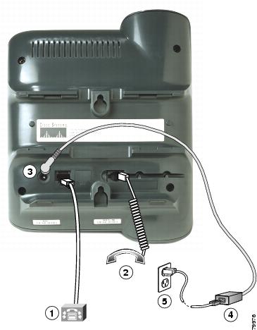
Refer to Figure 2-1 as you install the Cisco IP Phone 7905G.
Figure 2-1 Cisco IP Phone 7905G Rear Panel Connectors
Network port (10 Base-T)
Power supply with DC output connector (optional)
Handset port
5
AC Power cable with wall socket plug (optional)
DC adapter port (DC48V) (optional)
Mounting the Phone to the Wall
You can mount the Cisco IP Phone on the wall using special brackets available in a Cisco IP Phone wall mount kit. A wall mount kit must be ordered separately from the phone.
Before You Begin
To ensure that the handset attaches securely to a wall-mounted phone, remove the handset wall hook from the handset rest, rotate the hook 180 degrees, and reinsert the hook. Turning the hook exposes a lip on which the handset catches when the phone is vertical. For an illustrated procedure, see Installing the Wall Mount Kit for the Cisco IP Phone.
Connecting Cisco IP Phone 7905G to the Network
Note
Note
To install the Cisco IP Phone 7905G, complete the following steps:
Warning
Step 1
Step 2
Step 3
Step 4
After the phone is connected to its power source, a startup process begins. After several minutes, the LCD displays a neutral "ready" screen. The details on the screen might vary, but a ready screen typically displays the date and time, extension number, and available softkeys. Startup is complete and the phone is ready to use.
Softkeys point to feature options displayed along the bottom of the LCD screen. Softkeys are flexible—they change depending on the status of the phone. For example, one set of softkey options is displayed when the handset is picked up, and another set is displayed when the phone is not in use.
If the phone was preprogrammed with its basic configuration, it begins to automatically download its complete operating profile from the TFTP server. Initial preloaded bootload firmware is upgraded to firmware that supports a specific signalling protocol.
If an instruction sheet for the phone's basic configuration accompanies the Cisco IP Phone 7905G, the end user needs to complete the steps in the "Basic Configuration of the Cisco IP Phone 7905G" section before using the phone.
Note
Basic Configuration of the Cisco IP Phone 7905G
The basic configuration of the Cisco IP Phone 7905G provides the phone with the minimal information that it needs to download its complete operational configuration profile from a TFTP server. This information includes a value to enable TFTP downloads, a value for the URL for the TFTP server that stores the phone's complete configuration file (also known as a profile), and a value for the encryption key. Refer to Chapter 3, "Configuring the Cisco IP Phone 7905G" for information on working with profiles.
You can arrange for basic configuration to occur in either of the following two ways:
•
•
Preconfiguration Before Shipping
As the administrator, you can preconfigure the Cisco IP Phone 7905G before it is shipped to the end user, following the steps in the "Manual Configuration After Installation" section below.
Then, after the end user connects the phone as described in the "Physical Installation of Cisco IP Phone 7905G" section, the phone automatically downloads the configuration profile and the latest phone software from the TFTP server. The phone is ready for use within seconds.
Manual Configuration After Installation
If preconfiguration is not possible, the end user can manually enter the IP address of the TFTP server and the encryption key. You can provide this information by e-mail or on a sheet of paper that ships with the phone.
After the end user has connected the phone as described in the "Physical Installation of Cisco IP Phone 7905G" section, the basic configuration can be entered through the phone, following this procedure:
Step 1
Step 2
Step 3
Step 4
Step 5
Step 6
Step 7
Note
Use the NUM/ALPHA softkey to toggle between Numeric mode, in which the keypad keys produce numbers, and Alphabetic mode, in which the keypad keys produce letters. Enter the URL, and then press the Accept softkey.
Step 8
Step 9
Step 10
Verifying Installation
If you see the ready screen and hear a dial tone when you lift the handset, you have installed the Cisco IP Phone 7905G properly. Make a call to be sure, and follow the troubleshooting tips below if necessary.
Symptom You do not see the ready screen after lifting the telephone handset.
Possible Cause The power cord may not be connected properly.
Recommended Action Ensure that the cord is connected properly.
Symptom You do not hear a dial tone after lifting the telephone handset.
Possible Cause You may have used the wrong type of Ethernet cable (crossover or straight-through) or you may not have secured all cable connections.
Recommended Action Ensure that the appropriate Ethernet cable is used and that all cable connections are secure.
Symptom You place a call and receive a fast-busy tone.
Possible Cause Network connectivity between you and your party may be temporarily down.
Recommended Action Try your call again later.