-
Cisco CallManager System Guide, Release 3.1(1)
-
Index
-
Preface
-
Introduction
-
Cisco IP Telephony Overview
-
System Configuration Overview
-
System-Level Configuration Settings
-
Clustering
-
Redundancy
-
Call Admission Control
-
Cisco TFTP
-
Device Support
-
Services
-
Auto-Registration
-
Partitions and Calling Search Spaces
-
Understanding Route Plans
-
Understanding the LDAP Directory
-
Managing User Directory Information
-
Media Resource Management
-
Conference Bridges
-
Transcoders
-
Music On Hold
-
Media Termination Points
-
Catalyst DSP Resources for Transcoding and Conferencing
-
SMDI Voice Mail Integration
-
Cisco Unity Messaging Integration
-
Cisco uOne Voice Messaging Integration
-
Cisco DPA Integration
-
Call Park
-
Call Pickup and Group Call Pickup
-
Cisco IP Phone Services
-
Extension Mobility and Phone Login Features
-
Understanding Cisco WebAttendant
-
Custom Phone Rings
-
Understanding Voice Gateways
-
Cisco IP Phones
-
Computer Telephony Integration
-
Administrative Tools Overview
-
Administrative Accounts and Passwords
-
 Feedback
Table Of Contents
Bulk Administration Tool (BAT)
Administrative Reporting Tool (ART)
Remote Serviceability for Cisco CallManager
SNMP Instrumentation on the Cisco CallManager Server
Syslog Administrative Interface
CiscoWorks2000 Voice Management Features
Inventory Control and Reporting
CDR-Related Service Parameters
Where to Find More Information
Administrative Tools Overview
This section provides an overview of the following tools for Cisco CallManager administrators:
•
Bulk Administration Tool (BAT)
•
•
•
•
Bulk Administration Tool (BAT)
The Bulk Administration Tool (BAT), a plug-in application to Cisco CallManager, lets you add, update, or delete a large number of phones, users, Cisco VG200 gateways and ports, and Cisco Catalyst 6000 24 Port FXS analog interface modules to the Cisco CallManager database. Where this was previously a manual operation, BAT helps you automate the process and achieve much faster add, update, and delete operations.
BAT is a web-based application that requires Internet Explorer 4.01 Service Pack 2 or later or Netscape 4.5 or later. Cisco CallManager Administration provided the model for the look and feel of BAT.
You can access BAT from Cisco CallManager Administration and vice versa using the Application menu.
For more information on BAT, refer to the Bulk Administration Tool Guide for Cisco CallManager.
Administrative Reporting Tool (ART)
The Administrative Reporting Tool (ART) for Cisco CallManager 1.0(1), a web-based reporting application, generates the following reports that provide information regarding voice quality and generates reports on the gateway performance.
•
•
•
•
•
•
The Cisco CallManager records information regarding each call in Call Detail Records (CDRs) and Call Management Records (CMRs). CDRs and CMRs serve as the basic information source for ART and are stored in the ART database.
Retrieve the information that is not present in the CDR and CMRs, but is required for various reports, from the Light Weight Directory Access Protocol (LDAP), or the ART administrator must enter the information.
Access to ART is available only through a secured login to the package. The user ID and password for ART access are the same as the user profile set for Cisco CallManager.
Access ART using Internet Explorer 4.01 Service Pack 2 or later, or Netscape 4.5 or later.
To view the reports, ART requires the Adobe Acrobat reader, which you can download and install from the ART main screen.
For more information on ART, refer to the Administrative Reporting Tool Guide for Cisco CallManager.
Remote Serviceability for Cisco CallManager
Network management tools, if properly deployed, can provide the network administrator with a complete view into any enterprise network. With the advent of converged networks, it is imperative to have network management systems enable the following capabilities, at a minimum:
•
•
•
Cisco CallManager Remote Serviceability and CiscoWorks2000 provide the above capabilities, as well as other mechanisms, which enable visibility into the health and availability of the Cisco AVVID network. Considerable management features have been added, starting with Cisco CallManager Release 3.0, to permit visibility into the operation and reporting capability of a Cisco AVVID network. Table 35-1 lists the features that have been provided for network management applications to export data and, particularly for CiscoWorks2000, to provide reporting, proactive management, debugging, and other capabilities.
The following sections describe some of these features in more detail.
SNMP Instrumentation on the Cisco CallManager Server
Simple Network Management Protocol (SNMP) features for Cisco CallManager enable network management applications to retrieve data from the Cisco CallManager server in a standard fashion. The SNMP agent on the Cisco CallManager server is a subagent (extension agent) of the Microsoft Windows 2000 system agent. Therefore, you must enable the SNMP service on the Windows 2000 system for the SNMP instrumentation to function on the Cisco CallManager server.
Two Management Information Bases (MIBs) were introduced in Cisco CallManager Release 3.0 to permit the export of data as well as to support server advertisement and discovery. Both MIBs are extension agents and are independent of each other to facilitate future applications and functionality:
•
This MIB exports data from the Cisco CallManager database and other data sources. Examples of the exported data include Cisco CallManager group tables, region tables, time zone group tables, device pool tables, phone detail tables, gateway information tables and status traps, CDR host log table, performance counters, and so on.
•
This MIB uses Cisco Discovery Protocol (CDP) to enable CiscoWorks2000 to discover the Cisco CallManager server and to retrieve information from variables such as the interface table, deviceID, and so on. This is a limited implementation of the MIB and is essentially a subset of the CDP MIB related to advertisement (that is, the "tell" side of the MIB).
More detailed information on the CDP MIB is available on Cisco Connection Online (CCO) at
http://www.cisco.com/univercd/cc/td/doc/product/fhubs/fh300mib/mibcdp.htm
System Logging Components
The primary objective of system logging components is to provide a working solution for a centralized event logging and debug trace scheme in the multiplatform, distributed Cisco AVVID environment. In an open, distributed system, you can have multiple applications running on multiple systems. For ease of maintenance, have a common event log and a common trace log where Cisco CallManager can report events.
The interface to log events must be usable with most common programming languages. Also, with a common logging interface, the format of the log messages must be uniform across the system for ease of readability. Finally, the system should also have a common administrative interface to display and control all the event traces. Cisco CallManager and CiscoWorks2000 provide this functionality for unified message logging, display, and management. The following are the two main components to the system logging mechanism:
•
•
Syslog Collector
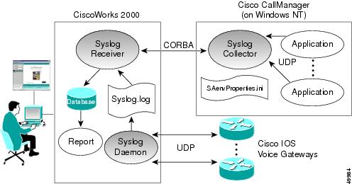
A Syslog Analyzer Collector (SAC) program runs as a Windows NT service on the Cisco CallManager server or any processing node in the network. The SAC program uses a configuration (.ini) file to set the environment variables such as the CiscoWorks2000 hostname and other parameters. This configuration file, SAenvProperties.ini, and its directory path are specified in the Windows NT registry, and the Cisco CallManager installation program sets their values. During startup time, the SAC tries to check in with the CiscoWorks2000 server to get some configuration and message filter information using a Common Object Request Broker Architecture (CORBA) method call. Then, it sends an initialization message that consists of the SAC hostname, the name of the syslog file, and other information for CiscoWorks2000 to keep track of it.
During normal operation, SAC reads messages from User Datagram Protocol (UDP) port 514. When it receives new messages, SAC processes the messages (for example, by performing filtering and time zone conversions) and then sends them to the CiscoWorks2000 server for storage and analysis. SAC also sends a status or statistic message periodically to the CiscoWorks2000 server. Figure 35-1 illustrates the interoperability of CiscoWorks2000 and Cisco CallManager.
Figure 35-1 Syslog Architecture for the Interoperability of Cisco CallManager and CiscoWorks2000
During installation of Cisco CallManager, the installation program normally prompts you to enter CiscoWorks2000 server information (for example, hostname or IP address). You can skip this step during installation and add the information later by modifying the contents of the file SAenvProperties.ini, located in \Program Files\Cisco\Bin. Set the SAC_SERVER and BINDNAME to the CiscoWorks2000 server.
The contents of the SAenvProperties.ini file are as follows:
FILE= /var/log/syslog_infoSAC_PORT = 514SAC_SERVER=<your_server_hostname.your_domain>SAC_SERVER_PORT = 42342VERSION = 1.1BINDNAME =<your_server_hostname>::SaReceiverDEBUG_LEVEL=4SA_APP_NAME=SyslogAnalyserSyslog Administrative Interface
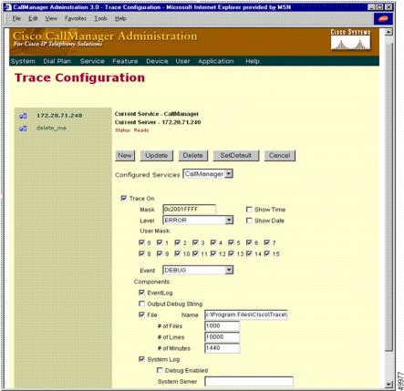
The Syslog administrative interface is a web-based interface that is part of Cisco Call Manager Administration, under Service > Trace. A new page shows the status of each trace flag and the trace output options of each service for each server in a Cisco CallManager cluster, as illustrated in Figure 35-2. You can enable or disable the trace flags from the administrative interface, which updates the trace configuration in the database layer.
Figure 35-2 Administrative User Interface for Syslog Trace Functions
Options also exist to enable the debug trace messages and to configure the Syslog server name. You should enable the debug trace message option only when there is little activity in the system. This method avoids putting excessive traffic on the network and lessens the burden on the system. You can send the debug trace messages to the Windows 2000 EventLog, to a local file, to the Syslog server, or to all three. Enter the Syslog server name only when using a syslog daemon other than the CiscoWorks2000 SAC as the Syslog server. Otherwise, leave the Syslog server name blank, and it will default to the local host name.
CiscoWorks2000 Voice Management Features
CiscoWorks2000 is a suite of products for network management, inventory control, analysis, and debugging. The Common Management Framework (CMF) in CiscoWorks2000 is a web-based application with various plug-in application suites that provide certain management feature sets.
Each application suite in the common web-based interface takes advantage of a common database. CiscoWorks2000 can run on either Windows NT or a Sun Solaris platform. Table 35-2 describes the respective components needed to complete the product suite for Cisco AVVID network management.
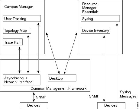
As mentioned, the CiscoWorks2000 architecture consists of a Common Management Framework (CMF) with a web-based desktop as a single point of management. An additional component, the asynchronous network interface (ANI), provides data collection services using Simple Network Management Protocol (SNMP), Cisco Discovery Protocol (CDP), and Interim Local Management Interface (ILMI) tables. Figure 35-3 illustrates this architecture.
Figure 35-3 CiscoWorks2000 Architecture
Discovery of the network occurs when you provide a seed device, preferably a router or a switch, through which the ANI can discover the network by reading its neighbors' CDP cache tables and SNMP variables, and can build a network topology map accordingly. The CMF also provides granular security, process control, and device information retrieval via SNMP. It uses CDP and the Cisco CallManager Management Information Bases to discover the Cisco CallManagers on the network and to retrieve and store their appropriate data tables.
Campus Manager
The ANI discovery process added the support for voice components of the Cisco AVVID network in Common Management Framework (CMF) Release 1.1.1. This CMF release supports the following voice devices and functions:
•
Cisco CallManager Release 3.0 (and later) contains the CDP driver, and it supports partial CDP MIB and SNMP. This is the "tell" side of CDP, so it is always an edge device, and it displays as a Cisco CallManager icon in the topology map.
•
The voice gateways are discovered in the same way as regular routers.
•
Cisco IP Phones contain the "tell" side of the CDP driver, but they do not support SNMP.
•
This feature provides tools for graphical VLAN configuration and logical topology mapping.
•
This feature provides tools for mobile user and dynamic VLAN tracking and configuration.
•
This feature traces Layer 2 and Layer 3 paths between two devices or end stations using IP address or directory number.
Because there are usually many Cisco IP Phones installed on a network, the ANI must handle the discovery of Cisco IP Phones separately to avoid overcrowding the network topology map. For this reason, CMF Release 1.1.1 ignores the CDP cache entries of the Cisco IP Phones in the neighboring switches and does not create any device objects for them; hence, daisy-chained IP phones are not discovered. The Cisco IP Phones are treated as end user devices and are discovered through User Tracking discovery, as described in the next section.
User Tracking
User Tracking (UT), a service module of the Campus Manager and ANI, specifically discovers end user nodes such as systems, Cisco CallManager hosts, Cisco IP Phones, and non-CDP systems as well. User Tracking performs an initial discovery of all hosts in the topology map and a subsequent discovery to maintain the user tracking table. You can specify a time limit for this subsequent discovery, and the default is 1 hour.
The initial UT discovery performs the following steps to generate a phone table:
1.
2.
–
–
–
Note
Trace Path Analysis
The Path Analysis tool, a part of the Campus Manager, traces IP connectivity between any managed devices in the network. The end points of the trace must be a managed device or end-user node in UT because there is a heavy reliance on accurate information for the trace to be performed. The trace displays end-to-end Layer 3 (IP) paths and, in some instances, the Layer 2 devices within the Layer 3 path. The Path Analysis tool offers two types of traces, data and voice. This chapter discusses only the voice trace.
A voice trace is performed using the call detail records (CDRs), and it also displays the IP path of the trace in case there is a need to discover the state of the network between two phones or between a phone and Cisco CallManager. The data path map can also display a reverse path, which is used if there is congruency in the Layer 3 IP routing paths. The non-CDR voice trace also performs a source-routed trace using the same IP precedence value as a voice call (RTP only). This trace is used if voice follows a different path than data and if it can take advantage of, or detect any problems with, any QoS that has been provisioned for voice.
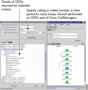
The CDR-based voice trace can accept three values for a trace: time period to match the call, calling number, and called number. Matching of the data occurs with the right-most digits entered. The path analysis tools search the CDRs of all the managed Cisco CallManager hosts in the database, and matched records are returned. The tools can display and examine the records with best-effort suggestions for possible causes of a problem and corrective actions.
Figure 35-4 shows an example trace path analysis, with Layer 2 and Layer 3 devices displayed.
Figure 35-4 Example Trace Path Analysis
Resource Manager Essentials
The CiscoWorks2000 LAN management solution is also bundled with the Resource Manager Essentials (RME), which are primarily responsible for inventory control, system configuration repository and configuration management, syslog server and syslog analysis, and other reporting functions. RME Release 3.1 is the minimum release that supports detailed reporting capabilities and manageability for Cisco CallManager hosts that are imported.
System logging capabilities of Cisco CallManager, described in the "System Logging Components" section, are well integrated with CiscoWorks2000. RME serves as a single point of management for Syslog Collector message filter configuration and device detail reporting for Cisco CallManager and other Cisco managed devices.
Inventory Control and Reporting
Cisco CallManager is supported in RME in the same manner as any Cisco device. The MIBs supported by Cisco CallManager are accessible through a standard SNMP agent. RME identifies the Cisco CallManager via the Compaq sysObjectID, so it is imperative to avoid exporting a similar system that is not running Cisco CallManager; otherwise, RME will waste resources by periodically collecting configuration information from the non-CallManager system.
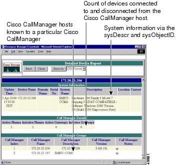
RME also creates a separate group in the device selector (a new system view named "Cisco CallManagers") once it detects that Cisco CallManager hosts have been imported for inventory and reporting management. Reports exposed for the device selector are intended to show data about the configuration and state of Cisco CallManager itself, and they do not report on information regarding the individual components configured on Cisco CallManager. Figure 35-5 shows an example device report from RME.
Figure 35-5 Example Device Report from RME
RME also supports report of Multi-Service Port Report (MSP). Essentially, RME evaluates, and the MSP report displays, all the managed Catalyst 4000 and 6000 switches that have inline power modules installed as well as their available ports for IP phone deployment.
System Logging Management
The server side (RME) of CiscoWorks2000 provides a web-based administrative interface to display the Syslog report from all of the devices in the managed network. There are two types of Syslog reports:
•
•
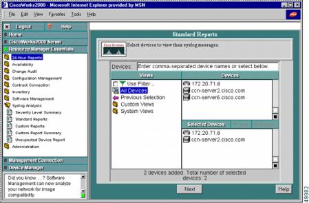
Any devices that support MIB II SNMP variables can be added to the device list of the CiscoWorks2000 configuration, and they are considered as managed devices. The Syslog messages from these managed devices are collected in the Syslog Standard Report. On the other hand, the Syslog messages from the unmanaged devices all go to the Unexpected Device Report. Figure 35-6 shows the administrative user interface for the Standard Report.
Figure 35-6 Standard Report in CiscoWorks2000
You can also use the administrative interface of CiscoWorks2000 to define custom reports such as user URL, automated action, and message filters (as shown in Figure 35-7). These features of the Syslog Analyzer and the administrative interface were updated in RME Release 3.1 to support Cisco CallManager and its suite of voice applications.
Syslog Message Filtering
In addition to System Diagnostic Interface (SDI) filtering, there are two places in the Syslog Analyzer where you can perform message filtering:
•
•
Note
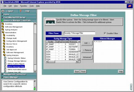
The filtering mechanism allows you to define filters that are based on the source, the facility code, the subfacility codes, severity levels, mnemonic codes, or patterns in the message. Figure 35-7 shows an example of defining a message filter in the CiscoWorks2000 administrative interface.
Figure 35-7 Message Filter Defined for a Remote SAC
Alarms
The Syslog Analyzer in CiscoWorks2000 has a web-based administrative interface to define an automatic action for a set of events or Syslog messages from particular devices. In future releases of CiscoWorks2000, this feature will be enhanced further to generate alarms or traps. Currently, the Syslog Analyzer can be used for event notification via either writing to a log file or generating an e-mail message. Cisco recommends that you configure the appropriate e-mail destination, whether that be to some e-mail receiver that can generate a page or to some Network Operation Center (NOC) alert e-mail alias. From an operational perspective, there would be a clear advantage to having event notification e-mails sent to an e-mail capable pager or cellular phone.
Call Detail Records
When CDR collection is enabled, Cisco CallManager writes call detail records (CDRs) to the SQL database as calls are made. CDR collection is enabled and configured through service parameters that are set in Cisco CallManager Administration. You must enable CDR collection on each Cisco CallManager in the cluster for which you want to generate records (see the "CDR-Related Service Parameters" section
All CDR records are written to the local database on each Cisco CallManager and then moved from the local database to the publisher database for the cluster in a low priority thread at 1-minute intervals.
If the local database is not available, then they are written to any of the other subscriber databases in the cluster. When the local database becomes available, the writing of new records resumes on the local database.
Enabling CDR Collection
CDR collection is enabled through a Cisco CallManager service parameter named CdrEnabled. To enable CDR collection:
1.
2.
3.
4.
5.
6.
7.
CDR-Related Service Parameters
The following tunable service parameters apply to CDRs:
•
•
•
Removing CDR Records
The CallManager application relies on post-processing applications such as ART or other 3rd-party packages to analyze CDR data. The removal of the CDR data should be done by the administrator when all post-processing applications are through with the data. Because this involves modifying the database, the SQL user CiscoCCMCDR should be used.
If CDR records accumulate to a configured maximum (as set by the MaxCdrRecords service parameter, which defaults to 1.5 million records), then the oldest CDR records are removed along with related CMR records once a day.
When removing CDR data after analysis, be sure to remove all related CMR records also.
Tips
CDR Database Access
The easiest way to read data from the SQL database is to use ODBC. A good connection string would look like one of the following examples depending on whether you need to get to the configuration data or CDRs:
DRIVER={SQL Server};SERVER=machineX;DATABASE=CCM0300
DRIVER={SQL Server};SERVER=machineX;DATABASE=CDR
Be sure to use the correct database name. Previous versions of the product had the CDR tables in the CCM0300 database. The tables have been moved to the CDR database. Also, you will need access to both the configuration database and CDR database to properly resolve the CDR information.
The machine that is the central collector of the CDR information is the machine serving the primary CCM0300 database. To determine the publisher database (machine and name) currently in use by the cluster
1.
2.
The Database field in the Database Information area displays the name of the Cisco CallManager server that is the publisher database for the cluster.
Access to CDR records is controlled through SQL Users. Table 35-3 specifies the UserID and password that should be used when accessing the Cisco CallManager database.
Where to Find More Information
Related Topics
•
•
Additional Cisco Documentation
•
•
•
•
•
•
•
•