Table Of Contents
Oracle JD Edwards on Cisco Unified Computing System with EMC VNX Storage
Cisco Unified Computing System
Design Considerations for Oracle JD Edwards Implementation on Cisco Unified Computing System
Scalable Architecture Using Cisco UCS Servers
EMC VNX5300—Block Storage for Oracle JD Edwards
Sizing Guidelines for Oracle JD Edwards
Oracle JD Edwards Deployment Architecture on Cisco Unified Computing System
Cisco Unified Computing System Configuration
Creating Uplink Ports Channels
Cisco UCS Service Profile Configuration
Creating Service Profile Templates
Creating a Service Profile From a Template and Associating it to a Cisco UCS Server Blade
Creating Storage Pools and RAID Groups
Configuring the Nexus Switches
Enabling Nexus 5548 Switch Licensing
Creating VSAN and Adding FC Interfaces
Configuring Ports 21-24 as FC Ports
Creating VLANs and Managing Traffic
Creating and Configuring Virtual Port Channel (VPC)
Modifying Service Profile for Boot Policy
Creating the Zoneset and Zones on Nexus 5548
Microsoft Windows 2008 R2 Installation
Oracle JD Edwards Installation
General Installation Requirements
JD Edwards Specific Installation Requirements
JD Edwards Deployment Server Installation Requirements
JD Edwards Enterprise Server Installation Requirements
JD Edwards Database Server Installation Requirements
JD Edwards HTML Server Installation Requirements
JD Edwards Port Numbers Installation
JD Edwards Deployment Server Install
Tools Upgrade on the Deployment Server
Installing the Enterprise Server
Installing the Database Server
Oracle HTTP Server Installation
Installing the OneWorld Client
Oracle JD Edwards Performance and Scalability
Interactive with Batch Test Scenario
Interactive with Batch on same Physical Server
Interactive with Batch on Separate Physical Server
Best Practices and Tuning Recommendations
Microsoft SQL Server 2008 R2 Configuration
JD Edwards Enterprise Server Configuration
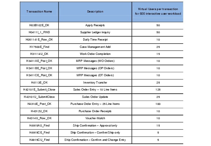
Appendix A—Workload Mix for Batch and Interactive Test
Appendix B—Reference Documents
About Cisco Validated Design (CVD) Program
Oracle JD Edwards on Cisco Unified Computing System with EMC VNX Storage
Executive Summary
Oracle JD Edwards is a suite of products from Oracle that caters to the Enterprise Resource Planning (ERP) requirement of an Organization. Oracle has three flag ship ERP Applications, Oracle E-Business Suite, PeopleSoft and JD Edwards. ERP Applications have been thriving and improving the productivity of Organizations for a couple of decades now. But with the increased complexity and extreme performance requirements, customers are constantly looking for better Infrastructure to host and run these Applications.
This Cisco Validated Design presents a differentiated Solution using Cisco Unified Computing System (UCS) that validates Oracle JD Edwards environment on Cisco UCS hosting SQL Server and Windows Operating System, with Cisco UCS Blade Servers, Nexus 5548 Switches, UCS Management System and EMC VNX5300 Storage platform. Cisco Oracle Competency Center tested, validated, benchmarked and showcased the Oracle JD Edwards ERP Application using Oracle Day in the life (DIL) Kit.
Target Audience
This Cisco Validated Design is intended to assist Solution Architects, JDE Project Manager, Infrastructure Manager, Sales Engineers, Field Engineers and Consultants in planning, design, and deployment of Oracle JD Edwards hosted on Cisco Unified Computing System (UCS) servers. This document assumes that the reader has an architectural understanding of the Cisco UCS servers, Nexus 5548 switch, Oracle JD Edwards, EMC® VNX5300™ Storage array, and related software.
Purpose of this Guide
This Cisco Validated Design showcases Oracle JD Edwards Performance and Scalability on Cisco UCS Platform and how enterprises can apply best practices for Cisco Unified Computing System, Cisco Nexus family of switches and EMC VNX5300 storage platform while deploying the Oracle JD Edwards application.
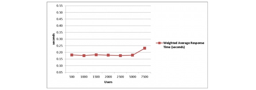
Design validation was achieved by executing Oracle JD Edwards Day in the Life (DIL) Kit on Cisco UCS Platform by benchmarking various Application workloads using HP's LoadRunner tool. Oracle JDE DIL kit comprises of interactive Application workloads and batch workload, Universal Batch Engine Processes (UBEs). The interactive Application Users were validated and benchmarked by scaling from 500 to 7500 concurrent users and various set of UBEs were also executed concurrently with 1000 Interactive users and 5000 Interactive user concurrent load. Achieving sub second response times for various JDE Application workloads with a large variation of interactive apps and UBEs , clearly demonstrate the suitability of UCS Serves for small to large Oracle JD Edwards and help customers to make an informed decision on choosing Cisco UCS for their JD Edwards implementation on Cisco Unified Computing System.
Business Needs
Customers constantly look value for money, when they transition from one platform to another or migrate from proprietary systems to commodity hardware platforms; they endeavor to improve Operational efficiency and optimal resource utilization.
Other important aspects are Management and Maintenance; ERP Applications are business critical Applications and need to be up and running all the time. Ease of Maintenance and efficient management with minimal staff and reduced budgets are pushing Infrastructure managers to balance uptime and ROI.
Server sprawl, old technologies that consume precious real estate space and power with increase in the cooling requirement have pushed customer to look for innovative technologies that can address some of these challenges.
Solution Overview
The Solution in the design guide demonstrates the deployment of Oracle JD Edwards on Cisco Unified Computing System with EMC VNX5300 as the storage system. The Oracle JD Edwards solution architecture is designed to run on multiple platforms and on multiple databases. In this deployment, the Oracle JD Edwards Enterprise One (JDE E1) Release 9.0.2 was deployed on Microsoft Windows 2008 R2. The JDE E1 database was hosted on Microsoft SQL Server 2008 R2, and the JDE HTML server ran on Oracle WebLogic Server Release 10.3.5.
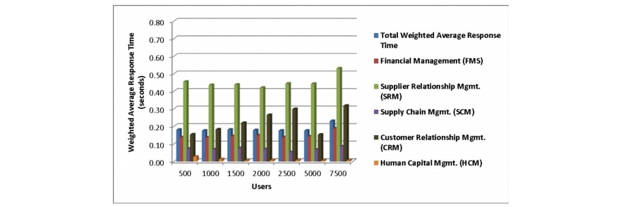
The deployment and testing was conducted in a Cisco® test and development environment to measure the performance of Oracle's JDE E1 Release 9.0.2 with Oracle's JDE E1 Day in the Life (DIL) test kit. The JDE E1 DIL kit is a suite of 17 test scripts that exercises representative transactions of the most popular JDE E1 applications, including SCM, SRM, HCM, CRM, and Financial Management. This complex mix of applications simulate workloads to more closely reflect customer environments
The solution describes the following aspects of Oracle JD Edwards deployment on Cisco Unified Computing System:
•
Sizing and Design guidelines for Oracle JD Edwards using JDE E1 DIL kit for both interactive and batch processes.
•
–
–
•
–
–
•
–
–
•
–
–
–
–
•
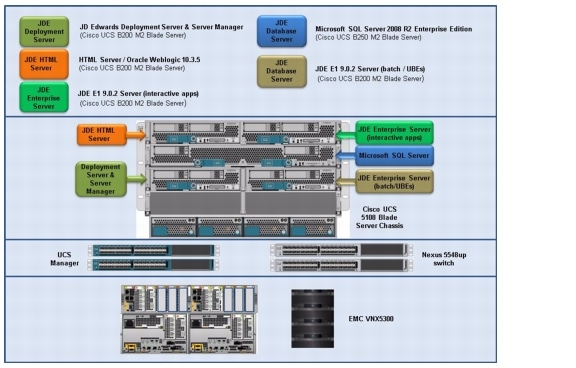
Figure 1 elaborates on the components of JD Edwards using Cisco UCS Servers.
Figure 1 Deployment Overview of JD Edwards Using Cisco UCS Servers
Technology Overview
Cisco Unified Computing System
The Cisco Unified Computing System is a next-generation data center platform that unites compute, network, and storage access. The platform, optimized for virtual environments, is designed using open industry-standard technologies and aims to reduce total cost of ownership (TCO) and increase business agility. The system integrates a low-latency; lossless 10 Gigabit Ethernet unified network fabric with enterprise-class, x86-architecture servers. It is an integrated, scalable, multi chassis platform in which all resources participate in a unified management domain.
The main components of Cisco Unified Computing System are:
•
•
•
•
•
The Cisco Unified Computing System is designed to deliver:
•
•
•
•
•
Cisco Unified Computing System is designed from the ground up to be programmable and self integrating. A server's entire hardware stack, ranging from server firmware and settings to network profiles, is configured through model-based management. With Cisco virtual interface cards, even the number and type of I/O interfaces is programmed dynamically, making every server ready to power any workload at any time.
With model-based management, administrators manipulate a model of a desired system configuration, associate a model's service profile with the hardware components, and the system configures automatically to match the model. This automation speeds provisioning and workload migration with accurate and rapid scalability. The result is increased IT staff productivity, improved compliance, and reduced risk of failures due to inconsistent configurations.
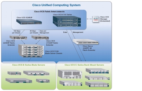
Cisco Fabric Extender technology reduces the number of system components to purchase, configure, manage, and maintain by condensing three network layers into one. It eliminates both blade server and hypervisor-based switches by connecting fabric interconnect ports directly to individual blade servers and virtual machines. Virtual networks are now managed exactly as physical networks are, but with massive scalability. This represents a radical simplification over traditional systems, reducing capital and operating costs while increasing business agility, simplifying and speeding deployment, and improving performance. Figure 2 shows the Cisco Unified Computing System components.
Figure 2 Cisco Unified Computing System Components
Fabric Interconnect
The Cisco® UCS 6200 Series Fabric Interconnect is a core part of the Cisco Unified Computing System, providing both network connectivity and management capabilities for the system. The Cisco UCS 6200 Series offers line-rate, low-latency, lossless 10 Gigabit Ethernet, Fibre Channel over Ethernet (FCoE) and Fibre Channel functions.
The Cisco UCS 6200 Series provides the management and communication backbone for the Cisco UCS B-Series Blade Servers and Cisco UCS 5100 Series Blade Server Chassis. All chassis, and therefore all blades, attached to the Cisco UCS 6200 Series Fabric Interconnects become part of a single, highly available management domain. In addition, by supporting unified fabric, the Cisco UCS 6200 Series provides both the LAN and SAN connectivity for all blades within its domain.
From a networking perspective, the Cisco UCS 6200 Series uses a cut-through architecture, supporting deterministic, low-latency, line-rate 10 Gigabit Ethernet on all ports, 1Tb switching capacity, 160 Gbps bandwidth per chassis, independent of packet size and enabled services. The product family supports Cisco low-latency, lossless 10 Gigabit Ethernet unified network fabric capabilities, which increase the reliability, efficiency, and scalability of Ethernet networks. The Fabric Interconnect supports multiple traffic classes over a lossless Ethernet fabric from a blade server through an interconnect. Significant TCO savings come from an FCoE-optimized server design in which network interface cards (NICs), host bus adapters (HBAs), cables, and switches can be consolidated. The Cisco Fabric Interconnect is shown in Figure 3.
Figure 3 Cisco UCS 6200 Series Fabric Interconnect
The following are the different types of Cisco Fabric Interconnects:
•
•
•
•
Cisco UCS 6296UP Fabric Interconnect
The Cisco UCS 6296UP 96-Port Fabric Interconnect is a 2RU 10 Gigabit Ethernet, FCoE and native Fibre Channel switch offering up to 1920-Gbps throughput and up to 96 ports. The switch has 48 1/10-Gbps fixed Ethernet, FCoE and Fiber Channel ports and three expansion slots. It doubles the switching capacity of the data center fabric to improve workload density from 960Gbps to 1.92 Tbps, reduces end-to-end latency by 40 percent to improve application performance and provides flexible unified ports to improve infrastructure agility and transition to a fully converged fabric.
Cisco UCS 6248UP Fabric Interconnect
The Cisco UCS 6248UP 48-Port Fabric Interconnect is a one-rack-unit (1RU) 10 Gigabit Ethernet, FCoE and Fiber Channel switch offering up to 960-Gbps throughput and up to 48 ports. The switch has 32 1/10-Gbps fixed Ethernet, FCoE and FC ports and one expansion slot.
Cisco UCS 2100 and 2200 Series Fabric Extenders
The Cisco UCS 2100 and 2200 Series Fabric Extenders multiplex and forward all traffic from blade servers in a chassis to a parent Cisco UCS fabric interconnect over from 10-Gbps unified fabric links. All traffic, even traffic between blades on the same chassis or virtual machines on the same blade, is forwarded to the parent interconnect, where network profiles are managed efficiently and effectively by the fabric interconnect. At the core of the Cisco UCS fabric extender are application-specific integrated circuit (ASIC) processors developed by Cisco that multiplex all traffic.
Up to two fabric extenders can be placed in a blade chassis.
•
•
Cisco UCS Blade Chassis
The Cisco UCS 5100 Series Blade Server Chassis is a crucial building block of the Cisco Unified Computing System, delivering a scalable and flexible blade server chassis.
The Cisco UCS 5108 Blade Server Chassis is six rack units (6RU) high and can mount in an industry-standard 19-inch rack. A single chassis can house up to eight half-width Cisco UCS B-Series Blade Servers and can accommodate both half-width and full-width blade form factors.
Four single-phase, hot-swappable power supplies are accessible from the front of the chassis. These power supplies are 92 percent efficient and can be configured to support non-redundant, N+ 1 redundant and grid-redundant configurations. The rear of the chassis contains eight hot-swappable fans, four power connectors (one per power supply), and two I/O bays for Cisco UCS 2104XP Fabric Extenders.
A passive mid-plane provides up to 20 Gbps of I/O bandwidth per server slot and up to 40 Gbps of I/O bandwidth for two slots. The chassis is capable of supporting future 40 Gigabit Ethernet standards. The Cisco UCS Blade Server Chassis is shown in Figure 4.
Figure 4 Cisco Blade Server Chassis (Front and Back View)
Cisco UCS Manager
Cisco Unified Computing System (CISCO UCS) Manager provides unified, embedded management of all software and hardware components of the Cisco UCS through an intuitive GUI, a command line interface (CLI), or an XML API. The Cisco UCS Manager provides unified management domain with centralized management capabilities and controls multiple chassis and thousands of virtual machines.
Cisco UCS Blade Server Types
The following are the different types of Cisco Blade Servers:
•
•
•
•
•
Cisco UCS B200 M3 Server
Delivering performance, versatility and density without compromise, the Cisco UCS B200 M3 Blade Server addresses the broadest set of workloads, from IT and Web Infrastructure through distributed database.
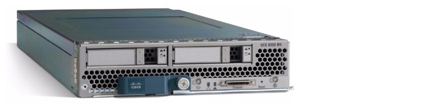
Building on the success of the Cisco UCS B200 M2 Blade Servers, the enterprise-class Cisco UCS B200 M3 further extends the capabilities of the Cisco Unified Computing System portfolio in a half-blade form factor. The Cisco UCS B200 M3 Server harnesses the power of the Intel® Xeon® E5-2600 processor product family, up to 384 GB of RAM, two hard drives, and up to 8 x 10GE to deliver exceptional levels of performance, memory expandability, and I/O throughput for nearly all applications. The Cisco UCS B200M3 Server is shown in Figure 5.
Figure 5 Cisco UCS B200 M3 Blade Server
Cisco UCS B200 M2 Server
The Cisco UCS B200 M2 Blade Server is a half-width, two-socket blade server. The system uses two Intel Xeon 5600 Series Processors, up to 96 GB of DDR3 memory, two optional hot-swappable small form factor (SFF) serial attached SCSI (SAS) disk drives, and a single mezzanine connector for up to 20 Gbps of I/O throughput. The server balances simplicity, performance, and density for production-level virtualization and other mainstream data center workloads. The Cisco UCS B200 M2 Server is shown in the Figure 6.
Figure 6 Cisco UCS B200 M2 Blade Server
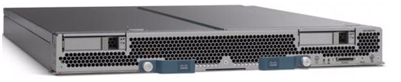
Cisco UCS B250 M2 Extended Memory Blade Server
The Cisco UCS B250 M2 Extended Memory Blade Server is a full-width, two-socket blade server featuring Cisco Extended Memory Technology. The system supports two Intel Xeon 5600 Series Processors, up to 384 GB of DDR3 memory, two optional SFF SAS disk drives, and two mezzanine connections for up to 40 Gbps of I/O throughput. The server increases performance and capacity for demanding virtualization and large-data-set workloads with greater memory capacity and throughput. The Cisco UCS Extended Memory Blade Server is shown in Figure 7.
Figure 7 Cisco UCS B250 M2 Extended Memory Blade Server
Cisco UCS B230 M2 Blade Servers
The Cisco UCS B230 M2 Blade Server is a full-slot, 2-socket blade server offering the performance and reliability of the Intel Xeon processor E7-2800 product family and up to 32 DIMM slots, which support up to 512 GB of memory. The Cisco UCS B230 M2 supports two SSD drives and one CNA mezzanine slot for up to 20 Gbps of I/O throughput. The Cisco UCS B230 M2 Blade Server platform delivers outstanding performance, memory, and I/O capacity to meet the diverse needs of virtualized environments with advanced reliability and exceptional scalability for the most demanding applications.
Cisco UCS B440 M2 High-Performance Blade Servers
The Cisco UCS B440 M2 High-Performance Blade Server is a full-slot, 2-socket blade server offering the performance and reliability of the Intel Xeon processor E7-4800 product family and up to 512 GB of memory. The Cisco UCS B440 M2 supports four SFF SAS/SSD drives and two CNA mezzanine slots for up to 40 Gbps of I/O throughput. The Cisco UCS B440 M2 blade server extends Cisco UCS by offering increased levels of performance, scalability, and reliability for mission-critical workloads.
Cisco UCS Service Profiles
Programmatically Deploying Server Resources
Cisco UCS Manager provides centralized management capabilities, creates a unified management domain, and serves as the central nervous system of the Cisco Unified Computing System. Cisco UCS Manager is embedded device management software that manages the system from end-to-end as a single logical entity through an intuitive GUI, CLI, or XML API. Cisco UCS Manager implements role- and policy-based management using service profiles and templates. This construct improves IT productivity and business agility. Now infrastructure can be provisioned in minutes instead of days, shifting IT's focus from maintenance to strategic initiatives.
Dynamic Provisioning with Service Profiles
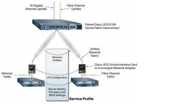
Cisco UCS resources are abstract in the sense that their identity, I/O configuration, MAC addresses and WWNs, firmware versions, BIOS boot order, and network attributes (including QoS settings, ACLs, pin groups, and threshold policies) all are programmable using a just-in-time deployment model. The manager stores this identity, connectivity, and configuration information in service profiles that reside on the Cisco UCS 6200 Series Fabric Interconnect. A service profile can be applied to any blade server to provision it with the characteristics required to support a specific software stack. A service profile allows server and network definitions to move within the management domain, enabling flexibility in the use of system resources. Service profile templates allow different classes of resources to be defined and applied to a number of resources, each with its own unique identities assigned from predetermined pools.
Service Profiles and Templates
A service profile contains configuration information about the server hardware, interfaces, fabric connectivity, and server and network identity. The Cisco UCS Manager provisions servers utilizing service profiles. The Cisco UCS Manager implements a role-based and policy-based management focused on service profiles and templates. A service profile can be applied to any blade server to provision it with the characteristics required to support a specific software stack. A service profile allows server and network definitions to move within the management domain, enabling flexibility in the use of system resources.
Service profile templates are stored in the Cisco UCS 6200 Series Fabric Interconnects for reuse by server, network, and storage administrators. Service profile templates consist of server requirements and the associated LAN and SAN connectivity. Service profile templates allow different classes of resources to be defined and applied to a number of resources, each with its own unique identities assigned from predetermined pools.
The Cisco UCS Manager can deploy the service profile on any physical server at any time. When a service profile is deployed to a server, the Cisco UCS Manager automatically configures the server, adapters, Fabric Extenders, and Fabric Interconnects to match the configuration specified in the service profile. A service profile template parameterizes the UIDs that differentiate between server instances.
This automation of device configuration reduces the number of manual steps required to configure servers, Network Interface Cards (NICs), Host Bus Adapters (HBAs), and LAN and SAN switches. Figure 8 shows the Service profile which contains abstracted server state information, creating an environment to store unique information about a server.
Figure 8 Service Profiles
Cisco Nexus 5548UP Switch
The Cisco Nexus 5548UP is a 1RU 1 Gigabit and 10 Gigabit Ethernet switch offering up to 960 gigabits per second throughput and scaling up to 48 ports. It offers 32 1/10 Gigabit Ethernet fixed enhanced Small Form-Factor Pluggable (SFP+) Ethernet/FCoE or 1/2/4/8-Gbps native FC unified ports and three expansion slots. These slots have a combination of Ethernet/FCoE and native FC ports. The Cisco Nexus 5548UP switch is shown in Figure 9.
Figure 9 Cisco Nexus 5548UP Switch
I/O Adapters
The Cisco UCS blade server has various Converged Network Adapters (CNA) options. The Cisco UCS M81KR Virtual Interface Card (VIC) option is used in this Cisco Validated Design.
This Cisco UCS M81KR VIC called as Palo Card is unique to the Cisco UCS blade system. This mezzanine card adapter is designed around a custom ASIC that is specifically intended for VMware-based virtualized systems. It uses custom drivers for the virtualized HBA and 10-GE network interface card. As is the case with the other Cisco CNAs, the Cisco UCS M81KR VIC encapsulates fiber channel traffic within the 10-GE packets for delivery to the Fabric Extender and the Fabric Interconnect.
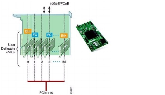
The Cisco UCS M81KR VIC provides the capability to create multiple VNICs (up to 128 in version 1.4) on the CNA. This allows complete I/O configurations to be provisioned in virtualized or non-virtualized environments using just-in-time provisioning, providing tremendous system flexibility and allowing consolidation of multiple physical adapters.
System security and manageability is improved by providing visibility and portability of network policies and security all the way to the virtual machines. Additional M81KR features like VN-Link technology and pass-through switching, minimize implementation overhead and complexity. The Cisco UCS M81KR VIC is as shown in Figure 10.
Figure 10 Cisco UCS M81KR VIrtual Interface Card
Cisco UCS Virtual Interface Card 1240
The Cisco UCS Virtual Interface Card (VIC) 1240 is a 4-port 10 Gigabit Ethernet, Fibre Channel over Ethernet (FCoE)-capable modular LAN on motherboard (mLOM) designed exclusively for the M3 generation of Cisco UCS B-Series Blade Servers. When used in combination with an optional Port Expander, the Cisco UCS VIC 1240 capabilities can be expanded to eight ports of 10 Gigabit Ethernet. The Cisco UCS VIC 1240 enables a policy-based, stateless, agile server infrastructure that can present up to 256 PCIe standards-compliant interfaces to the host that can be dynamically configured as either network interface cards (NICs) or host bus adapters (HBAs). In addition, the Cisco UCS VIC 1240 supports Cisco Data Center Virtual Machine Fabric Extender (VM-FEX) technology, which extends the Cisco UCS fabric interconnect ports to virtual machines, simplifying server virtualization deployment.
Cisco UCS Virtual Interface Card 1280
The Cisco UCS Virtual Interface Card (VIC) 1280 is an eight-port 10 Gigabit Ethernet, Fibre Channel over Ethernet (FCoE)-capable mezzanine card designed exclusively for Cisco UCS B-Series Blade Servers. The card enables a policy-based, stateless, agile server infrastructure that can present up to 256 PCIe standards-compliant interfaces to the host that can be dynamically configured as either network interface cards (NICs) or host bus adapters (HBAs). In addition, the Cisco UCS VIC 1280 supports Cisco Virtual Machine Fabric Extender (VM-FEX) technology, which extends the Cisco UCS Fabric Interconnect ports to virtual machines, simplifying server virtualization deployment.
EMC VNX Storage Family
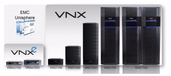
The EMC VNX family of storage systems represents EMC's next generation of unified storage, optimized for virtual environments, while offering a cost effective choice for deploying mission-critical enterprise applications such as Oracle JD EDwards. The massive virtualization and consolidation trends with servers demand a new storage technology that is dynamic and scalable. The EMC VNX series meets these requirements and offers several software and hardware features for optimally deploying enterprise applications such. The EMC VNX family is shown in Figure 11.
Figure 11 The EMC VNX Family of Unified Storage Platforms
A key distinction of the VNX Series is support for both block and file-based external storage access over a variety of access protocols, including Fibre Channel (FC), iSCSI, FCoE, NFS, and CIFS network shared file access. Furthermore, data stored in one of these systems, whether accessed as block or file-based storage objects, is managed uniformly via Unisphere®, a web-based interface window. Additional information on Unisphere can be found on emc.com in the white paper titled: Introducing EMC Unisphere: A Common Midrange Element Manager.
EMC VNX Storage Platforms
The EMC VNX Series continues the EMC tradition of providing some of the highest data reliability and availability in the industry. Apart from this they also include in their design a boost in performance and bandwidth to address the sustained data access bandwidth rates. The new system design has also placed heavy emphasis on storage efficiencies and density, as well as crucial green storage factors, such as a smaller data center footprint, lower power consumption, and improvements in power reporting.
The VNX has many features that help improve availability. Data protection is heightened by the lack of any single point of failure from the network to the actual disk drive in which the data is stored. The data resides on the VNX for block storage system, which delivers data availability, protection, and performance. The VNX uses RAID technology to protect the data at the drive level. All data paths to and from the network are redundant.
The basic design principle for the VNX Series storage platform includes the VNX for file front end and the VNX for block hardware for the storage processors on the back end. The control flow is handled by the storage processors in block-only systems and the control station in the file-enabled systems. The VNX OE for block software has been designed to ensure the I/O is well balanced between the two SPs. At the time of provisioning, the odd number LUNs are owned by one SP and even number LUNs are owned by the other. This results in LUNs being evenly distributed between the two SPs. If a failover occurs, LUNs would trespass over to the alternate path/SP. EMC PowerPath® restores the "default": path once the error condition is recovered. This brings the LUNs again in a balanced state between the SPs. For more information on VNX Series, see: http://www.emc.com/collateral/hardware/data-sheets/h8520-vnx-family-ds.pdf.
Key efficiency features available with the VNX Series include FAST Cache and FAST VP.
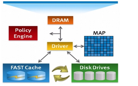
FAST Cache Technology
FAST Cache is a storage performance optimization feature that provides immediate access to frequently accessed data. In traditional storage arrays, the DRAM caches are too small to maintain the hot data for a long period of time. Very few storage arrays give an option to non-disruptively expand DRAM cache, even if they support DRAM cache expansion. FAST Cache extends the available cache to customers by up to 2 TB using enterprise Flash drives. FAST Cache tracks the data temperature at 64 KB granularity and copies hot data to the Flash drives once its temperature reaches a certain threshold. After a data chunk gets copied to FAST Cache, the subsequent accesses to that chunk of data will be served at Flash latencies. Eventually, when the data temperature cools down, the data chunks get evicted from FAST Cache and will be replaced by newer hot data. FAST Cache uses a simple Least Recently Used (LRU) mechanism to evict the data chunks.
FAST Cache is built on the premise that the overall applications' latencies can improve when most frequently accessed data is maintained on a relatively smaller sized, but faster storage medium, like Flash drives. FAST Cache identifies the most frequently accessed data which is temporary and copies it to the flash drives automatically and non-disruptively. The data movement is completely transparent to applications, thereby making this technology application-agnostic and management-free. For example, FAST Cache can be enabled or disabled on any storage pool simply by selecting/clearing the "FAST Cache" storage pool property in advanced settings.
FAST Cache can be selectively enabled on a few or all storage pools within a storage array, depending on application performance requirements and SLAs.
There are several distinctions to EMC FAST Cache:
•
•
•
•
Figure 12 EMC FAST Cache
Additional information on EMC Fast Cache is documented in the white paper titled EMC FAST Cache—A Detailed Review which is available at: http://www.emc.com/collateral/software/white-papers/h8046-clariion-celerra-unified-fast-cache-wp.pdf.
FAST VP
VNX FAST VP is a policy-based auto-tiering solution for enterprise applications. FAST VP operates at a granularity of 1 GB, referred to as a "slice." The goal of FAST VP is to efficiently utilize storage tiers to lower customers' TCO by tiering colder slices of data to high-capacity drives, such as NL-SAS, and to increase performance by keeping hotter slices of data on performance drives, such as Flash drives. This occurs automatically and transparently to the host environment. High locality of data is important to realize the benefits of FAST VP. When FAST VP relocates data, it will move the entire slice to the new storage tier. To successfully identify and move the correct slices, FAST VP automatically collects and analyzes statistics prior to relocating data. Customers can initiate the relocation of slices manually or automatically by using a configurable, automated scheduler that can be accessed from the Unisphere management tool. The multi-tiered storage pool allows FAST VP to fully utilize all the storage tiers: Flash, SAS, and NL-SAS. The creation of a storage pool allows for the aggregation of multiple RAID groups, using different storage tiers, into one object. The LUNs created out of the storage pool can be either thickly or thinly provisioned. These "pool LUNs" are no longer bound to a single storage tier. Instead, they can be spread across different storage tiers within the same storage pool. If you create a storage pool with one tier (Flash, SAS, or NL-SAS), then FAST VP has no impact on the performance of the system. To operate FAST VP, you need at least two tiers.
Additional information on EMC FAST VP for Unified Storage is documented in the white paper titled EMC FAST VP for Unified Storage System - A Detailed Review, see: http://www.emc.com/collateral/software/white-papers/h8058-fast-vp-unified-storage-wp.pdf.
FAST Cache and FAST VP are offered in a FAST Suite package as part of the VNX Total Efficiency Pack. This pack includes the FAST Suite which automatically optimizes for the highest system performance and lowest storage cost simultaneously. In addition, this pack includes the Security and Compliance Suite which keeps data safe from changes, deletions, and malicious activity. For additional information on this Total Efficiency Pack as well as other offerings such as the Total Protection Pack, see: http://www.emc.com/collateral/software/data-sheet/h8509-vnx-software-suites-ds.pdf.
EMC PowerPath
EMC PowerPath is host-based software that provides automated data path management and load-balancing capabilities for heterogeneous server, network, and storage deployed in physical and virtual environments. A critical IT challenge is being able to provide predictable, consistent application availability and performance across a diverse collection of platforms. PowerPath is designed to address those challenges, helping IT meet service-level agreements and scale-out mission-critical applications.
This software supports up to 32 paths from multiple HBAs (iSCSI TCI/IP Offload Engines [TOEs] or FCoE CNAs) to multiple storage ports when the multipathing license is applied. Without the multipathing license, PowerPath will use only a single port of one adapter (PowerPath SE). In this mode, the single active port can be zoned to a maximum of two storage ports. This configuration provides storage port failover only, not host-based load balancing or host-based failover. It is supported, but not recommended, if the customer wants true I/O load balancing at the host and also HBA failover.
PowerPath balances the I/O load on a host-by-host basis. It maintains statistics on all I/O for all paths. For each I/O request, PowerPath intelligently chooses the most under utilized path available. The available under utilized path is chosen based on statistics and heuristics, and the load-balancing and failover policy in effect.
In addition to the load balancing capability, PowerPath also automates path failover and recovery for high availability. If a path fails, I/O is redirected to another viable path within the path set. This redirection is transparent to the application, which is not aware of the error on the initial path. This avoids sending I/O errors to the application. Important features of PowerPath include standardized path management, optimized load balancing, and automated I/O path failover and recovery.
For more information on Powerpath, see: http://www.emc.com/collateral/software/data-sheet/l751-powerpath-ve-multipathing-ds.pdf.
Oracle JD Edwards
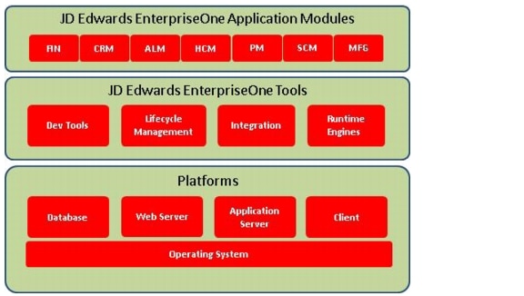
Oracle's JD Edwards is the ERP solution of choice for many small and medium-sized businesses (SMBs). JDE E1 offers an attractive combination of a large number of easy-to-deploy and easy-to-use ERP applications across multiple industries. These applications include Supply Chain Management (SCM), Human Capital Management (HCM), Supplier Relationship Management (SRM), Financials, and Customer Relationship Management (CRM). The various components of JD Edwards are elaborated in Figure 13.
Figure 13 JD Edwards Components
HTML Server
HTML Server is the interface of the JDE to the outside world. It allows the JDE ERP Users to connect to their Applications using their Browsers via the Web server. It is one of the Tiers of the standard three-tier JDE Architecture. HTML Server is just not an interface, it has logic and runs Web Services which processes some of the data and only the result set is sent through the WAN to the end users.
Enterprise Server
Enterprise Server hosts the JDE Applications that execute all the basic functions of the JDE ERP systems, like running the Transaction processing service, Batch Services, data replication, security and all the time stamp and distributed processing happens at this layer. Multiple enterprise server can be added for scalability, especially when we need to apply Electronic Software Updates (ESU's) to one server while the other is online.
Database Server
Database Server in a JDE environment is used to host the data. It simply is a data repository and is used to process JDE logic. The JDE Database server can run many supported databases like Oracle , SQL Server, DB2 or Access. Since this server does not run any Applications as mentioned the only licensing that is required for this server is the database license, hence the server should be sized correctly. If this server has excess capacity the UBE's can be run on this server to improve their performance.
Deployment Server
Deployment server essentially is a centralized software (C Code) repository for deploying software packages to all the servers and workstations that are part of the Cisco JDE solution. Although the Deployment server is not a business critical server, it is very important to note that it is a critical piece of the JDE Architecture, without which the Installation, upgrade, development or modification of packages (codes) or reports would become impossible.
Server Manager
The Server Manager is a key JDE software component that helps customers deploy latest JDE tools software onto various JDE Servers that are registered with the server manager. The server manager is web based and enables life cycle management of JDE products like the Enterprise server and HTML server via a web based console. It has built in abilities for configuration management and it maintains an audit history of changes made to the components and configuration of various JDE Server software.
Batch Server
Batch processes (UBE's) are background processes requiring no operator intervention or interactivity. One of most important batch process in JDE is MRP Process. Batch Process can be scheduled using a Process Scheduler which runs in the Batch Server. JDE customers running a high volume of reports often split the load on their Enterprise server such that they have one or more Batch servers which handle the high volume reporting (UBE) loads, thereby freeing up their enterprise server to handle interactive user loads more efficiently. This leads to better interactive application and UBE performance due to the expanded scaling afforded by the additional hardware.
Design Considerations for Oracle JD Edwards Implementation on Cisco Unified Computing System
The design document provides best practices for designing JD Edwards environments, demonstrates several advantages to organizations choosing the Cisco UCS platform and are applicable for organization of all sizes. There are several options which need to be considered vis-à-vis JD Edwards HTML Server, JDE E1 application server for interactive and batch (UBE) processes and most importantly the scalability and ease of deployment and maintenance of Hardware installed for JD Edwards deployment.
Scalable Architecture Using Cisco UCS Servers
An obvious immediate benefit with Cisco is a single trusted vendor providing all the components needed for a JD Edwards deployment with the ability to provide scalable platform, dynamic provisioning, failover with minimal downtimes and reliability.
Some of the capabilities offered by Cisco United Computing System which complement the scalable architecture include the following:
•
•
–
–
–
To accurately design JD Edwards on any hardware configuration, we need to understand the characteristics of each tier in JDE deployment vis-à-vis CPU, memory and I/O operations. For instance JDE Enterprise Server for Interactive is both CPU and memory intensive but is low on disk utilization whereas the database server is more memory and disk intensive rather than CPU utilization. Some of the important characteristics to design JD Edwards on Cisco UCS Server are elaborated Table 1.
Table 1 JD Edwards Design Considerations
Boot from SAN
Boot from SAN is a critical feature which helps to achieve stateless computing in which there is no static binding between a physical server and the OS / applications hosted on that server. The OS is installed on a SAN LUN and is booted using the service profile. When the service profile is moved to another server, the server policy and the PWWN of the HBAs will also move along with the service profile. The new server takes the identity of the old server and looks identical to the old server.
The following are the benefits of boot from SAN:
•
–
–
–
–
•
•
•
•
•
With boot from SAN, the server image resides on the SAN and the server communicates with the SAN through a Host Bus Adapter (HBA). The HBA BIOS contain instructions that enable the server to find the boot disk. After Power OnSelf Test (POST), the server hardware component fetches the designated boot device in the hardware BOIS settings. Once the hardware detects the boot device, it follows the regular boot process.
EMC VNX5300—Block Storage for Oracle JD Edwards
Oracle JD Edwards data is traditionally stored in any of the supported RDBMS such as SQL Server using block storage. In our current implementation, the EMC VNX5300 storage system is used for block storage. The EMC VNX5300's capability of block access is leveraged in this solution,
The VNX 5300 configured for this JD Edwards workload utilizes a DPE with 15 x 3.5" drive form factor. It includes four onboard 8 Gb/s Fibre Channel ports and two 6 Gb/s SAS ports for back-end connectivity on each storage processor. Each SP in the enclosure has a power supply module and two UltraFlex I/O module slots, Both I/O module slots may be populated on this model. Any slots without I/O modules will be populated with blanks (to ensure proper airflow). The front of the DPE houses the first tray of drives. The VNX 5300 configured for this JDE workload is configured with a mix of SAS drives, SSDs and NL-SAS drives, with LUNs carved out using heterogeneous storage pools leveraging FAST VP to ensure meeting both the storage capacity as well as the performance demands required. FAST Cache is enabled to ensure faster response times for both read and write operations. The storage connectivity provided to the Cisco UCS environment is comprised of Fibre Channel connectivity from the on-board 8Gb FC connections on each Storage Processor.
Sizing Guidelines for Oracle JD Edwards
Sizing ERP deployments is a complicated process, and getting it right depends a lot on the inputs provided by customers on how they intend to use the ERP system and what their priorities are in terms of end user as well as corporate expectations.
Some of the common questions related to ERP sizing such as the number of concurrent interactive users using the system, total number of ERP end users, the kind of applications that the end users will access as well as number of reports and type of reports generated during peak activity can help size the system for optimal performance. Analyzing the demand characteristics during different time periods in the fiscal year that the JDE system is expected to handle is necessary to do a proper sizing.
The JDE Edwards configuration used in the present deployment was geared to handle a very high workload of end users running heavy SRM interactive applications as well as a high number of batch processes. A physical three-tier solution with the Enterprise, HTML Web and Database all residing of different physical machines was used to provide an optimal solution in terms of end user response times as well as optimal batch throughput.
The following sections briefly describe the sizing aspects of each tier of the three tier JD Edwards deployment architecture.
JDE HTML Server
The JDE HTML server serves end user interactive application requests from JDE users. The JDE HTML server loads the application forms and requests services from the JDE Enterprise server for application processing based on form input. Some very lightweight application logic also runs on the JDE HTML Server. .Client requests do result in significant load on the JDE HTML servers since the JDE HTML servers make and manage database as well as network connections. The JDE HTML server's utilization of CPU and memory depends heavily on the number of interactive users using the server. Disk utilization is not a major factor in the sizing of the JDE HTML Server.
Typically, on the Windows Server, the number of interactive users per JVM should be capped to around 250 interactive users for optimal performance.
JDE Enterprise Server
The JDE Enterprise Server acts as the central point for serving requests for application logic. The JDE EnterpriseOne clients make requests for application processing and depending upon the JDE environment used as well as user preferences, the input data is then processed and returned back to the client. The Call Object kernels running on the JDE Enterprise server are delegated the responsibility of processing end user application processing requests and the Security kernel handles the responsibility of ensuring authentication of the end users .The application processing is CPU intensive and the CPU frequency and number of cores available to the Enterprise server plays a large part affecting the performance and throughput of the system. As the number of interactive users requests grow, the memory requirements of the JDE Enterprise server also increases. This is also true for the batch (UBE) reports that the JDE Enterprise server processes.
The typical sizing recommendation for number of users per call object kernel on Windows Server would be between 8 - 12 users/call object kernels and about 1 security kernel for every 50 interactive users. The in memory cache usage of call object kernels increase with user load so it is typical for the memory usage of individual call objects to increase with increase in user loads, as and when more users are serviced by them.
JDE Database Server
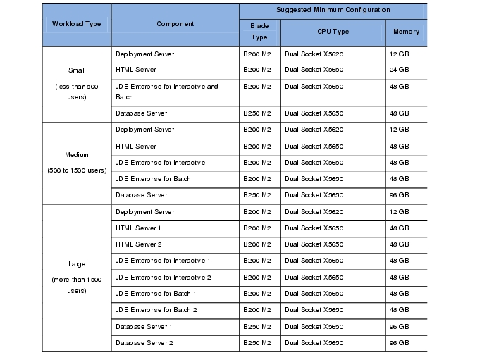
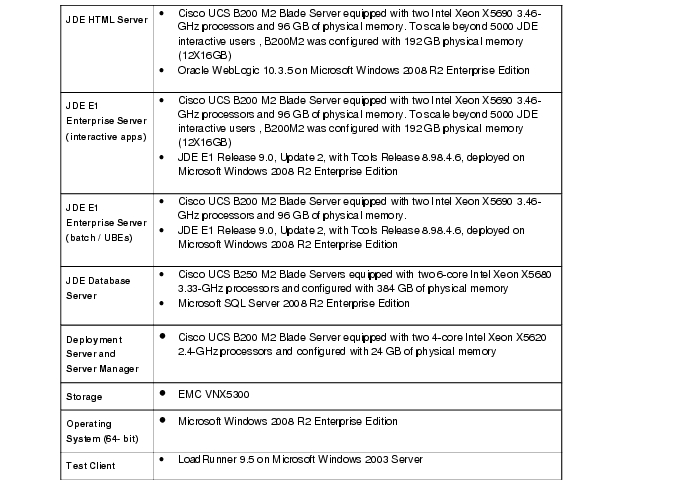
The JDE Database Server services the data requests made by both the JDE Enterprise and JDE HTML Servers. The JDE Database Server sizing depends on the type of reports being processed as well as the interactive user loads. Some JDE reports can be very Disk I/O intensive and depending on the kind of reports being processed, careful consideration needs to be given to disk layout. If the SQL Server database has ample memory available to it and the memory is utilized to cache SQL Server data it can benefit application performance by reducing disk I/O operations. The JDE Database server typically benefits from having faster disk and high memory allocation. The suggested minimum server configuration, to deploy Oracle JD Edwards on Cisco UCS with Microsoft Windows and SQL Server 2008 R2 is detailed in Table 2.
Table 2 Oracle JD Edwards on Cisco Unified Computing System—Suggested Minimum Server Configuration
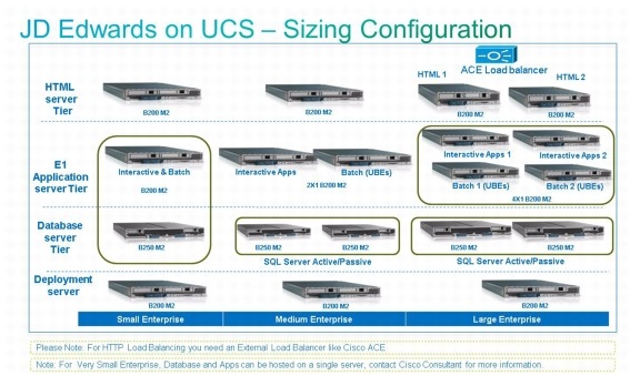
A typical Cisco UCS server configuration in ideal lab conditions for small, medium and large servers, is elaborated in Figure 14. The configuration may vary depending on customer workload and technology landscape.
Figure 14 JD Edwards on Cisco Unified Computing System—Sizing Chart
Oracle JD Edwards Deployment Architecture on Cisco Unified Computing System
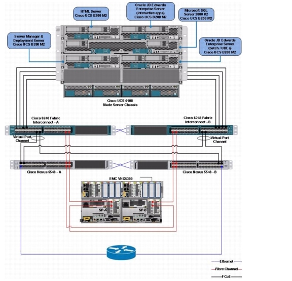
The deployment architecture of Oracle JD Edwards on Cisco UCS is elaborated in Figure 15.
Figure 15 Deployment Architecture of JD Edwards on Cisco Unified Computing System
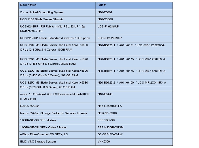
The configuration presented in this document is based on the following main components (Table 3).
Table 3 Configuration Components
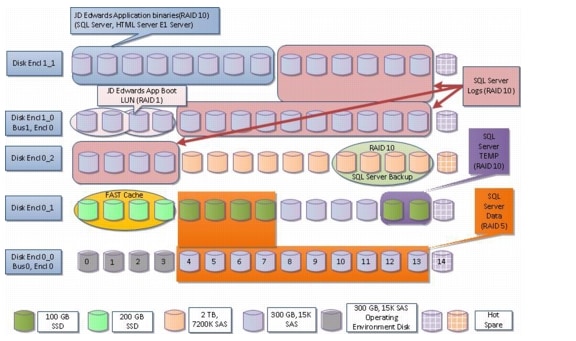
The Disk layout carved on EMC VNX5300 JD Edwards deployment on Cisco Unified Computing Systems elaborated in Figure 16.
Figure 16 JD Edwards Disk Layout on EMC VNX5300
Infrastructure Setup
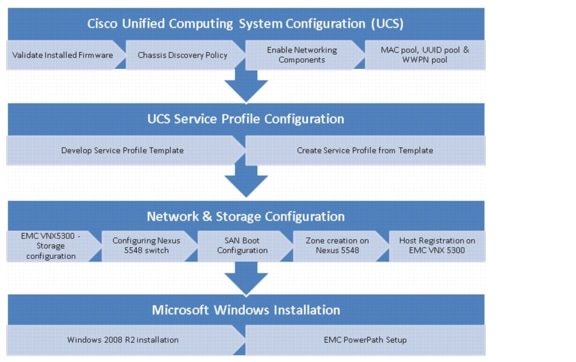
This section elaborates on the infrastructure setup details used to deploy Oracle JD Edwards on Cisco Unified Computing System with EMC VNX5300. The high-level workflow to configure the system is elaborated in Figure 17.
Figure 17 Workflow
Cisco Unified Computing System Configuration
This section details the Cisco UCS configuration that is done as part of the infrastructure build for deployment of Oracle JD Edwards. The racking, power and installation of the chassis are described in the install guide: http://www.cisco.com/en/US/docs/unified_computing/Cisco UCS/hw/chassis/install/Cisco UCS5108_install.html) and it is beyond the scope of this document. More details on each step can be found in the following documents:
•
•
Validate Installed Firmware
To log into Cisco UCS Manager, perform the following steps:
1.
2.
3.
4.
5.
6.
7.
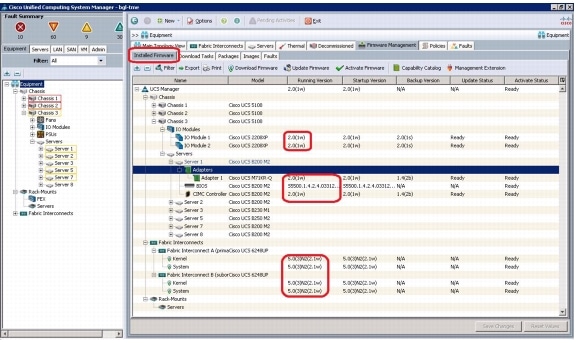
Verification: The Installed Firmware should be displayed as 2.0(1w) as shown in Figure 18.
Figure 18 Firmware Verification
Chassis Discovery Policy
To edit the chassis discovery policy, perform the following steps:
1.
2.
3.
4.
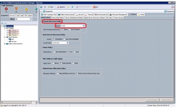
Verification: The chassis discovery policy configured to 4-link is displayed as shown in Figure 19.
Figure 19 Chassis Discovery Policy
Enabling Network Components
To enabling Fiber Channel, servers, and uplink ports, perform the following steps:
1.
2.
3.
4.
5.
6.
7.
8.
9.
10.
11.
12.
13.
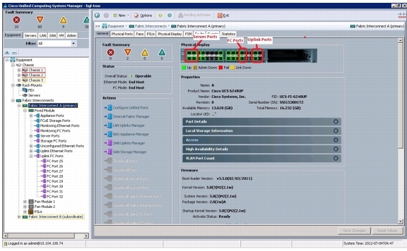
Verification: Check if all configured links show their status as "up" as shown in the figure below for Fabric Interconnect A. This can also be verified on the Cisco Nexus switch side by running "show int status" and all the ports connected to the Cisco UCS fabric interconnects are shown as "up."
Note
Figure 20 Configured Links on Fabric Interconnect A
Creating MAC Address Pools
To create MAC Address pools, perform the following steps:
1.
2.
Note
3.
4.
5.
6.
7.
8.
Note
9.
10.
11.
12.
13.
14.
15.
16.
17.
18.
Note
19.
20.
21.
22.
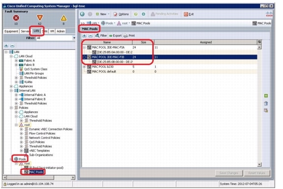
Verification: Select LAN tab > Pools > root. Select MAC Pools and it expands to show the MAC pools created. On the right pane, details of the MAC pools are displayed as shown Figure 21.
Figure 21 MAC Pool Details
Creating WWPN Pools
To create WWPN pools, perform the following steps:
1.
2.
Note
3.
4.
5.
6.
7.
8.
Note
9.
10.
11.
12.
13.
14.
15.
16.
17.
18.
19.
20.
21.
22.
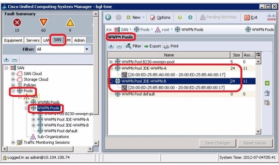
Verification: The new name with the 24 block size is shown in Figure 22.
Figure 22 WWPN Pool Details
Creating WWNN Pools
To create WWNN pools, perform the following steps:
1.
2.
3.
4.
5.
6.
7.
8.
9.
10.
11.
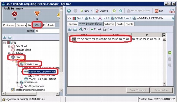
Verification: The new name with the 24 block size displays in the right panel when the WWNN pool is selected on the left panel, as shown in Figure 23.
Figure 23 WWNN Pool Details
Creating UUID Suffix Pools
To create UUID suffix pools, perform the following steps:
1.
2.
3.
4.
5.
6.
7.
8.
9.
10.
11.
12.
13.
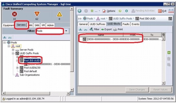
Verification: Make sure that the UUID suffix pool created is displayed as shown in Figure 24.
Figure 24 UUID Suffix Pool Details
Creating VLANs
To create VLANs, perform the following steps:
1.
Note
2.
3.
4.
5.
6.
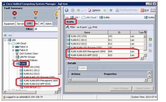
Verification: Select LAN tab > LAN Cloud > VLANs. Open VLANs and all of the created VLANs are displayed. The right pane provides the details of all individual VLANs as shown in Figure 25.
Figure 25 Details of Created VLANS
Creating Uplink Ports Channels
To create uplink port channels to Nexus 5548 switches, perform the following steps:
1.
Note
2.
3.
4.
5.
6.
7.
8.
9.
10.
11.
12.
13.
14.
15.
16.
17.
18.
19.
20.
21.
22.
23.
24.
25.
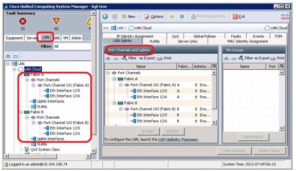
Verification: Select LAN tab > LAN Cloud. On the right pane, select the LAN Uplinks and expand the Port channels listed as shown in Figure 26.
Note
Figure 26 Port Channel Details
Creating VSANs
To create VSANs, perform the following steps:
1.
2.
3.
4.
5.
6.
7.
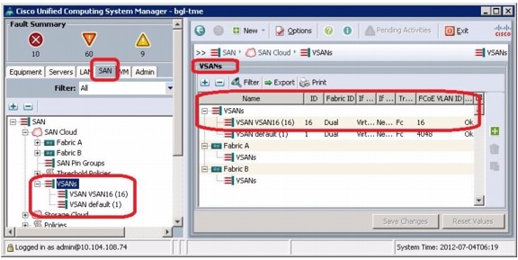
Verification: Select SAN tab >SAN Cloud >VSANs on the left panel. The right panel displays the created VSANs as shown in Figure 27.
Figure 27 VSAN Details
Cisco UCS Service Profile Configuration
An important aspect of configuring a physical server in a Cisco UCS 5108 chassis is to develop a service profile through Cisco UCS Manager. Service profile is an extension of the virtual machine abstraction applied to physical servers. The definition has been expanded to include elements of the environment that span the entire data center, encapsulating the server identity (LAN and SAN addressing, I/O configurations, firmware versions, boot order, network VLAN, physical port, and quality-of-service [QoS] policies) in logical "service profiles" that can be dynamically created and associated with any physical server in the system within minutes rather than hours or days. The association of service profiles with physical servers is performed as a simple, single operation. It enables migration of identities between servers in the environment without requiring any physical configuration changes and facilitates rapid bare metal provisioning of replacements for failed servers.
Service profiles can be created in several ways:
•
•
•
In the present scenario we created a Service profile initial template and thereafter instantiate service profile through the template.
•
•
•
•
Creating Service Profile Templates
To create service profile templates, perform the following steps:
Step 1
Step 2
Step 3
1.
a.
b.
c.
d.
2.
a.
b.
c.
d.
Note
e.
f.
g.
h.
i.
j.
k.
l.
m.
n.
o.
p.
q.
r.
s.
3.
a.
b.
c.
d.
e.
f.
g.
h.
i.
j.
k.
l.
m.
n.
o.
p.
4.
a.
b.
c.
5.
a.
6.
a.
b.
c.
Creating a Service Profile From a Template and Associating it to a Cisco UCS Server Blade
To create a service profile from the template and associating it to a server blade, perform the following steps:
1.
2.
3.
4.
5.
6.
7.
8.
9.
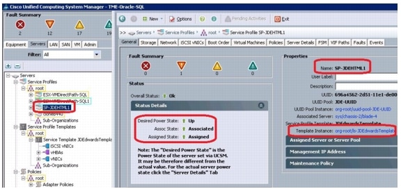
Figure 28 Associated Service Profile
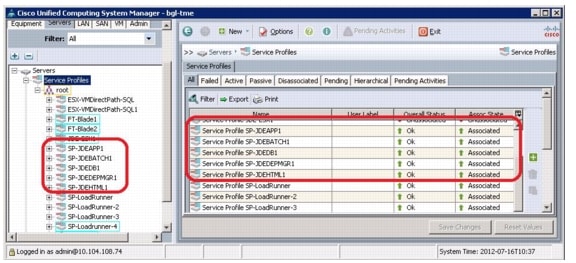
The following service profiles were associated; SQL Database Server, JDE Enterprise Server, JDE Batch Server and JDE Deployment Server. All the service profiles created are shown in Figure 29.
Figure 29 Service Profiles Associated with JD Edwards Servers
Configuring the EMC VNX5300
The current JD Edwards deployment uses EMC VNX5300 storage, connected to the Cisco Unified Computing System. It uses the EMC FAST Cache as well as EMC FAST Virtual Pool capability .
•
•
•
•
•
•
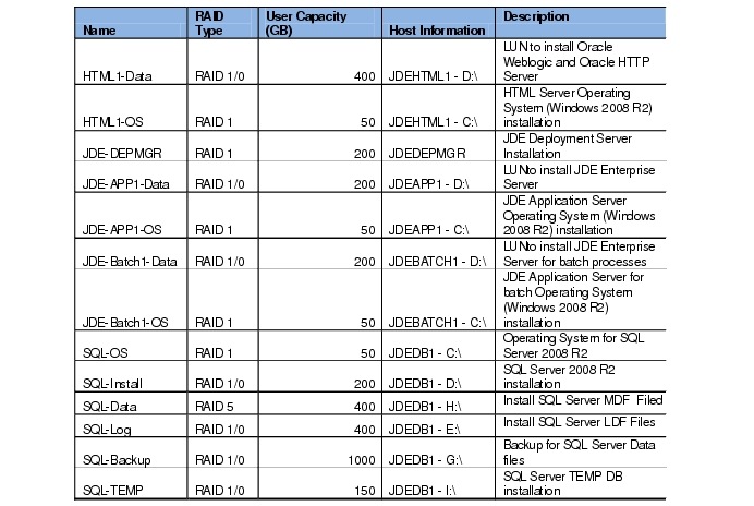
LUNs carved from the EMC VNX storage forming the disk layout for the JD Edwards deployment are elaborated in Table 4.
Table 4 LUN Configuration for JD Edwards Deployment
Creating Storage Pools and RAID Groups
To create storage pools and RAID groups, perform the following steps:
1.
2.
a.
b.
c.
d.
3.
a.
b.
c.
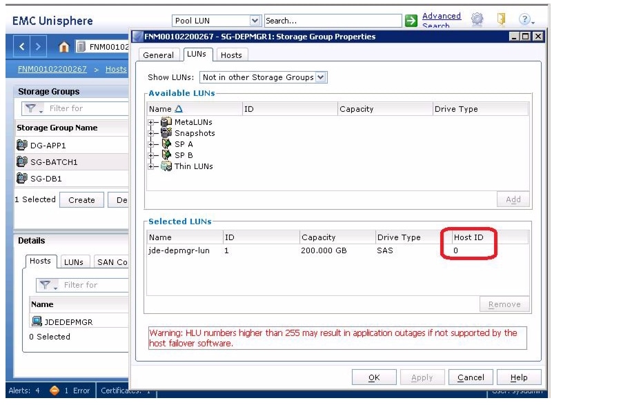
4.
a.
b.
Note
Figure 30 Storage Group Host ID
5.
a.
b.
6.
a.
b.
c.
Configuring the Nexus Switches
To configure the Nexus 5548 Switch, perform the following steps:
Setting up the Nexus 5548 Switch
To setup the Nexus 5548 switch, perform the following steps for Cisco Nexus 5548 Switch A (rk5-SS21-n5548-a):
1.
2.
3.
4.
5.
6.
7.
8.
9.
10.
11.
12.
13.
14.
15.
16.
17.
18.
19.
20.
21.
Note
22.
23.
24.
To setup the Nexus 5548 switch, perform the following steps for Cisco Nexus 5548 Switch B (rk5-SS21-n5548-b):
1.
2.
3.
4.
5.
6.
7.
8.
9.
10.
11.
12.
13.
14.
15.
16.
17.
18.
19.
20.
21.
Note
22.
23.
24.
Enabling Nexus 5548 Switch Licensing
To enable appropriate Nexus 5548 switch licensing, perform the following steps for both Cisco Nexus 5548 A - (rk5-SS21-n5548-a), and Cisco Nexus 5548 B - (rk5-SS21-n5548-b) separately:
1.
2.
3.
4.
5.
6.
7.
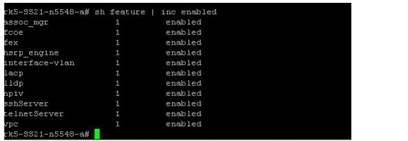
Verification: Figure 31lists the enabled features on Nexus 5548 (show feature | include enabled)
Figure 31 Features Enabled on the Nexus 5548
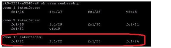
Creating VSAN and Adding FC Interfaces
To create VSAN and adding FC interfaces, perform the following steps for both Cisco Nexus 5548 A - (rk5-SS21-n5548-a), and Cisco Nexus 5548 B - (rk5-SS21-n5548-b) separately:
1.
2.
3.
4.
5.
6.
Verification: Figure 32 lists port fc1/21-24 under vsan 16.
Figure 32 Set VSAN ID on Nexus 5548
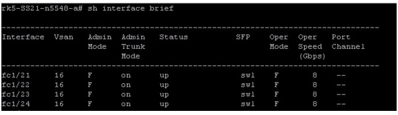
Configuring Ports 21-24 as FC Ports
To configure the ports 21-24 as FC ports, perform the following steps for both Cisco Nexus 5548 A - (rk5-SS21-n5548-a), and Cisco Nexus 5548 B - (rk5-SS21-n5548-b) separately:
1.
2.
3.
4.
5.
Verification: As shown in Figure 33, the command "show interface brief" should list these interfaces as FC (Admin Mode F).
Figure 33 Enable FC Mode on Nexus 5548 Ports
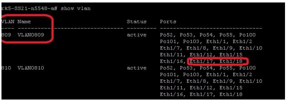
Creating VLANs and Managing Traffic
To create the necessary VLANs, for example, VLAN 809 and managing data traffic for example, VLAN 810 - data traffic, perform the following steps for both Cisco Nexus 5548 A - (rk5-SS21-n5548-a), and Cisco Nexus 5548 B - (rk5-SS21-n5548-b) separately:
1.
2.
3.
4.
5.
6.
7.
8.
9.
10.
Verification: The command "show vlan" lists the VLANs and interfaces assigned to it. Or, the command "show run interface <interface name>" will show the configuration for a given interface or port channel. Figure 34 lists the executed command.
Figure 34 Show VLAN on Nexus 5548
Creating and Configuring Virtual Port Channel (VPC)
To create and configure the VPC, perform the following steps for both Cisco Nexus 5548 A - (rk5-SS21-n5548-a), and Cisco Nexus 5548 B - (rk5-SS21-n5548-b) separately:
1.
2.
3.
4.
5.
6.
7.
8.
9.
10.
11.
12.
13.
14.
15.
16.
17.
18.
19.
20.
21.
22.
23.
24.
25.
26.
27.
Verification: "show vpc" command will list the VPC properties with VPC peer-link status as "success" and Consistency status as "success."
rk5-SS21-n5548-a# show vpc
Legend:
(*) - local vPC is down, forwarding via vPC peer-link
vPC domain id : 100
Peer status : peer adjacency formed ok
vPC keep-alive status : peer is alive
Configuration consistency status: success
Per-vlan consistency status : success
Type-2 consistency status : success
vPC role : primary
Number of vPCs configured : 10
Peer Gateway : Disabled
Dual-active excluded VLANs : -
Graceful Consistency Check : Enabled
vPC Peer-link status
---------------------------------------------------------------------
id Port Status Active vlans
-- ---- ------ --------------------------------------------------
1 Po100 up 1,192,194,809-812
vPC status
----------------------------------------------------------------------------
id Port Status Consistency Reason Active vlans
------ ----------- ------ ----------- -------------------------- -----------
101 Po101 up success success 1,192,194,809-812
When you perform the VPC configuration on Cisco Nexus 5548 B - (rk5-SS21-n5548-b) and execute "show vpc" will display the following :
rk5-SS21-n5548-b# show vpc
Legend:
(*) - local vPC is down, forwarding via vPC peer-link
vPC domain id : 100
Peer status : peer adjacency formed ok
vPC keep-alive status : peer is alive
Configuration consistency status: success
Per-vlan consistency status : success
Type-2 consistency status : success
vPC role : secondary
Number of vPCs configured : 12
Peer Gateway : Disabled
Dual-active excluded VLANs : -
Graceful Consistency Check : Enabled
vPC Peer-link status
---------------------------------------------------------------------
id Port Status Active vlans
-- ---- ------ --------------------------------------------------
1 Po100 up 1,192,194,809-812
vPC status
----------------------------------------------------------------------------
id Port Status Consistency Reason Active vlans
------ ----------- ------ ----------- -------------------------- -----------
103 Po103 up success success 1,192,194,8
09-812
SAN Boot Configuration
In the present deployment, the Cisco UCS Servers are booted from SAN (EMC VNX5300). With boot from SAN, the OS image resides on the SAN and the server communicates with the SAN through a host bus adapter (HBA). The HBAs BIOS contain the instructions that enable the server to find the boot disk. After power on self test (POST), the server hardware component fetches the boot device that is designated as the boot device in the hardware BOIS settings. When the hardware detects the boot device, it follows the regular boot process.
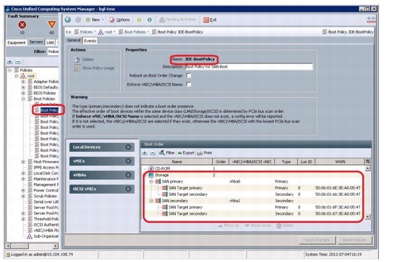
Modifying Service Profile for Boot Policy
In this setup, vhba0 and vhba1 are used for SAN Boot and the other two configured HBA's for example, vhba2 and vhba3 are for JD Edwards installation. Storage SAN WWPN ports will be connected in the boot policy as shown below:
To modify the Service Profile for boot policy, perform the following steps:
1.
2.
3.
4.
5.
6.
Note
7.
8.
9.
10.
Figure 35 Boot Policy Service Profile
11.
Note
Update the other service profiles as done with the boot policy JDE-BootPolicy to boot from the SAN after creating necessary LUNs / Storage groups in Storage array and Zones in Nexus Switches. The other service profiles are SP-JDEApp1, SP-JDEDepMgr, SP-JDESQL and SP-JDEBatch1.
Creating the Zoneset and Zones on Nexus 5548
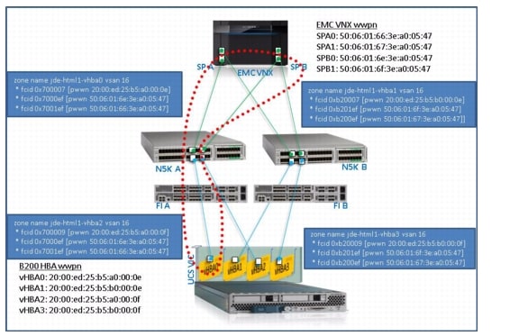
Figure 36 shows the zoning configuration. This is the recommended configuration and the steps to create the zoneset and zones are described below.
Figure 36 SAN Zoning Configuration
To create the zoneset and zone, perform the following steps for Cisco Nexus 5548 Switch A - (rk5-SS21-n5548-a):
1) Identify Storage and Server WWPNs
rk2-n5548-a# sh flogi database
--------------------------------------------------------------------------------
INTERFACE VSAN FCID PORT NAME NODE NAME
--------------------------------------------------------------------------------
fc1/21 16 0x700006 20:1d:54:7f:ee:3a:4f:40 20:10:54:7f:ee:3a:4f:41
fc1/21 16 0x700007 20:00:ed:25:b5:a0:00:0e 20:de:00:25:b5:00:00:0f
fc1/22 16 0x700008 20:1e:54:7f:ee:3a:4f:40 20:10:54:7f:ee:3a:4f:41
fc1/23 16 0x7000ef 50:06:01:6e:3e:a0:05:47 50:06:01:60:be:a0:05:47
fc1/24 16 0x7001ef 50:06:01:66:3e:a0:05:47 50:06:01:60:be:a0:05:47
fc1/25 3 0x2b000c 10:00:00:00:c9:9d:f2:d8 20:00:00:00:c9:9d:f2:d8
fc1/29 3 0x2b0002 20:41:00:05:9b:77:4b:00 20:03:00:05:9b:77:4b:01
fc1/29 3 0x2b0005 20:00:00:25:b5:04:01:0e 20:00:00:25:b5:00:00:0e
fc1/29 3 0x2b0007 20:00:00:25:b5:04:01:0c 20:00:00:25:b5:00:00:1d
fc1/29 3 0x2b0009 20:00:00:25:b5:04:01:0a 20:00:00:25:b5:00:00:1c
fc1/30 3 0x2b0000 20:42:00:05:9b:77:4b:00 20:03:00:05:9b:77:4b:01
fc1/30 3 0x2b0006 20:00:00:25:b5:04:01:0d 20:00:00:25:b5:00:00:0d
fc1/30 3 0x2b0008 20:00:00:25:b5:04:01:0b 20:00:00:25:b5:00:00:0c
fc1/31 3 0x2b0003 50:0a:09:83:9d:93:40:7f 50:0a:09:80:8d:93:40:7f
Total number of flogi = 14.
Note: The storage and servewr WWPNs are marked in bold.
2) Create zone and zoneset
rk2-n5548-a# conf t
Enter configuration commands, one per line. End with CNTL/Z.
rk2-n5548-a(config)# zone name jde-html1-vhba0 vsan 16
rk2-n5548-a(config-zone)# member pwwn 20:00:ed:25:b5:a0:00:0e
rk2-n5548-a(config-zone)# member pwwn 50:06:01:6e:3e:a0:05:47
rk2-n5548-a(config-zone)# member pwwn 50:06:01:66:3e:a0:05:47
rk2-n5548-a(config-zone)# zoneset name jde-n5k1 vsan 16
rk2-n5548-a(config-zoneset)# member jde-html1-vhba0
rk2-n5548-a(config-zoneset)# zoneset activate name jde-n5k1 vsan 16
Zoneset activation initiated. check zone status
rk2-n5548-a(config)# sh zo
zone zone-attribute-group zoneset
rk2-n5548-a(config)# sh zoneset active vsan 16
zoneset name jde-n5k1 vsan 16
zone name jde-html1-vhba0 vsan 16
* fcid 0x700007 [pwwn 20:00:ed:25:b5:a0:00:0e]
* fcid 0x7000ef [pwwn 50:06:01:6e:3e:a0:05:47]
* fcid 0x7001ef [pwwn 50:06:01:66:3e:a0:05:47]
rk2-n5548-a(config)# copy r s
[########################################] 100%
To create the zone configuration for Cisco Nexus 5548 B (rk5-SS21-n5548-b), follow the steps as described for Nexus 5548 A (rk5-SS21-n5548-a). These steps are defined as below.
1) Identify Storage and Server WWPNs
rk2-n5548-b# sh flogi database
--------------------------------------------------------------------------------
INTERFACE VSAN FCID PORT NAME NODE NAME
--------------------------------------------------------------------------------
fc1/21 16 0xb20008 20:1e:54:7f:ee:3a:4e:80 20:10:54:7f:ee:3a:4e:81
fc1/22 16 0xb20006 20:1d:54:7f:ee:3a:4e:80 20:10:54:7f:ee:3a:4e:81
fc1/22 16 0xb20007 20:00:ed:25:b5:b0:00:0e 20:de:00:25:b5:00:00:0f
fc1/23 16 0xb201ef 50:06:01:6f:3e:a0:05:47 50:06:01:60:be:a0:05:47
fc1/24 16 0xb200ef 50:06:01:67:3e:a0:05:47 50:06:01:60:be:a0:05:47
fc1/25 3 0x15000c 10:00:00:00:c9:9d:f2:d9 20:00:00:00:c9:9d:f2:d9
fc1/29 3 0x150002 20:41:00:05:73:a2:66:80 20:03:00:05:73:a2:66:81
fc1/29 3 0x150005 20:00:00:25:b5:04:02:0e 20:00:00:25:b5:00:00:0e
fc1/29 3 0x150007 20:00:00:25:b5:04:02:0c 20:00:00:25:b5:00:00:1d
fc1/29 3 0x150009 20:00:00:25:b5:04:02:0a 20:00:00:25:b5:00:00:1c
fc1/30 3 0x150000 20:42:00:05:73:a2:66:80 20:03:00:05:73:a2:66:81
fc1/30 3 0x150006 20:00:00:25:b5:04:02:0d 20:00:00:25:b5:00:00:0d
fc1/30 3 0x150008 20:00:00:25:b5:04:02:0b 20:00:00:25:b5:00:00:0c
fc1/31 3 0x150004 50:0a:09:83:8d:93:40:7f 50:0a:09:80:8d:93:40:7f
fc1/32 3 0x150003 50:0a:09:84:9d:93:40:7f 50:0a:09:80:8d:93:40:7f
Total number of flogi = 15.
2) Create zone and zoneset
rk2-n5548-b# conf t
Enter configuration commands, one per line. End with CNTL/Z.
rk2-n5548-b(config)# zone name jde-html1-vhba1 vsan 16
rk2-n5548-b(config-zone)# member pwwn 20:00:ed:25:b5:b0:00:0e
rk2-n5548-b(config-zone)# member pwwn 50:06:01:6f:3e:a0:05:47
rk2-n5548-b(config-zone)# member pwwn 50:06:01:67:3e:a0:05:47
rk2-n5548-b(config-zone)# zoneset name jde-n5k2 vsan 16
rk2-n5548-b(config-zoneset)# member jde-html1-vhba1
rk2-n5548-b(config-zoneset)# zoneset activate name jde-n5k2 vsan 16
Zoneset activation initiated. check zone status
rk2-n5548-b(config)# sh zoneset active vsan 16
zoneset name jde-n5k2 vsan 16
zone name jde-html1-vhba1 vsan 16
* fcid 0xb20007 [pwwn 20:00:ed:25:b5:b0:00:0e]
* fcid 0xb201ef [pwwn 50:06:01:6f:3e:a0:05:47]
* fcid 0xb200ef [pwwn 50:06:01:67:3e:a0:05:47]
rk2-n5548-b(config)# copy r s
[########################################] 100%
rk2-n5548-b(config)#
Create the zones for the other blades in both Nexus switches. This can be verified by executing "'show zoneset active vsan 16" command in the Nexus switch.
rk5-SS21-n5548-a# sh zoneset active vsan 16
zoneset name jde-n5k1 vsan 16
zone name jde-html1-vhba0 vsan 16
* fcid 0x700007 [pwwn 20:00:ed:25:b5:a0:00:0e]
* fcid 0x7000ef [pwwn 50:06:01:6e:3e:a0:05:47]
* fcid 0x7001ef [pwwn 50:06:01:66:3e:a0:05:47]
zone name jde-depmgr1-vhba0 vsan 16
* fcid 0x70000a [pwwn 20:00:ed:25:b5:a0:00:0c]
* fcid 0x7000ef [pwwn 50:06:01:6e:3e:a0:05:47]
* fcid 0x7001ef [pwwn 50:06:01:66:3e:a0:05:47]
zone name jde-db1-vhba0 vsan 16
* fcid 0x70000c [pwwn 20:00:ed:25:b5:a0:00:0b]
* fcid 0x7000ef [pwwn 50:06:01:6e:3e:a0:05:47]
* fcid 0x7001ef [pwwn 50:06:01:66:3e:a0:05:47]
zone name jde-app1-vhba0 vsan 16
* fcid 0x70000b [pwwn 20:00:ed:25:b5:a0:00:09]
* fcid 0x7000ef [pwwn 50:06:01:6e:3e:a0:05:47]
* fcid 0x7001ef [pwwn 50:06:01:66:3e:a0:05:47]
zone name jde-batch1-vhba0 vsan 16
* fcid 0x700011 [pwwn 20:00:ed:25:b5:a0:00:17]
* fcid 0x7000ef [pwwn 50:06:01:6e:3e:a0:05:47]
* fcid 0x7001ef [pwwn 50:06:01:66:3e:a0:05:47]
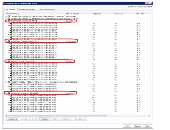
Host and Storage Connectivity
To establish the Host connectivity at the EMC VNX5300 array, perform the following steps:
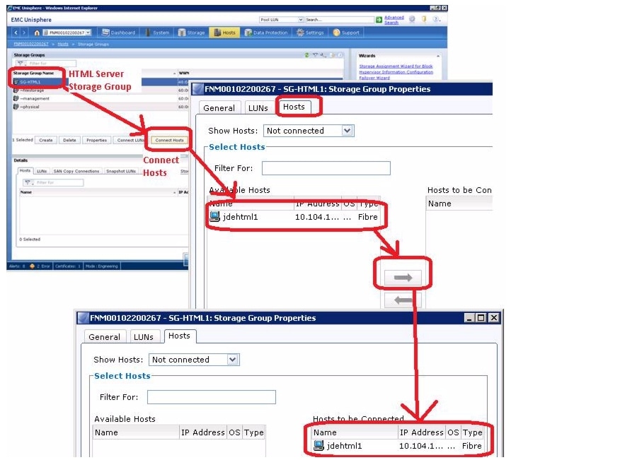
Connecting Storage to the Host
Since the zones are configured in the Cisco Nexus switches with the Host HBA WWPNs, they will appear in the EMC VNX5300—"Host connectivity status."
To connect storage to the host, perform the following steps:
1.
2.
Note
3.
4.
5.
6.
Figure 37 Storage Group—Host Association
Storage connectivity for the other blades can be established by following the same steps as described above.
Microsoft Windows 2008 R2 Installation
After making sure that the Boot LUN has been made visible to the host, Microsoft Windows 2008 R2 can be installed. For details on installing Windows 2008 R2 operation system on B-Series server, please refer to: http://www.cisco.com/en/US/docs/unified_computing/ucs/sw/b/os/windows/install/2008-vmedia-install.html
EMC PowerPath Setup
For the present Oracle JD Edwards implementation, PowerPath Version 5.5 (Build 289) is installed, as host-based software that provides automated data path management and load-balancing capabilities for EMC VNX5300 connected to Cisco UCS servers. The Naviagent installation is done first (NaviHostAgent-Win-32-x86-en_US-6.29.6.0.35-1) and then the PowerPath executable (EMCPower.X64.signed.5.5.b289) is installed post OS installation. Naviagent and Powerpath can be installed on the other blades using the same steps.
To install Naviagent on Windows 2008 R2, perform the following steps:
1.
2.
3.
4.
Figure 38 Storage Group—Add IP Address of Target EMC System
5.
6.
7.
Figure 39 EMC Unisphere—Connective Statuw Manual to Automatic Host Management
To Install PowerPath on Windows 2008 R2, perform the following steps.
1.
2.
3.
4.
5.
6.
Figure 40 Confirmation for PowerPath Installation
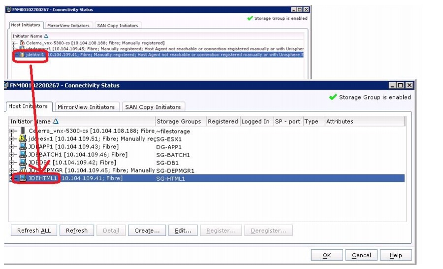
When the steps for all JD Edwards deployment servers are completed, the connectivity status on EMC Unisphere looks as shown in Figure 41.
Figure 41 Connectivity Status of Registered Servers
Oracle JD Edwards Installation
The Installation of Oracle JD Edwards (JDE) 9.0.2 suite on Windows 2008R2, with SQL Server 2008R2 as the RDBMS is described in the following sections.
Pre-Requisites
•
•
•
•
•
General Installation Requirements
The following are the general requirements before installing the JDE Enterprise Server.
•
•
•
•
JD Edwards Specific Installation Requirements
The following are some of the requirements to be considered for JD Edwards installation:
•
•
JD Edwards Deployment Server Installation Requirements
The following are of the requirements specific to JD Edwards Deployment:
•
•
•
•
•
•
JD Edwards Enterprise Server Installation Requirements
The following are the requirements specific to JD Edwards Enterprise Server:
•
•
•
JD Edwards Database Server Installation Requirements
The following are the requirements specific to JD Edwards Database Server:
•
•
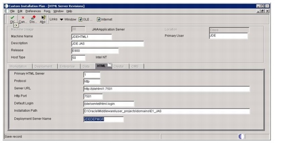
JD Edwards HTML Server Installation Requirements
The following are the requirements specific to JD Edwards HTML Server:
•
•
•
•
JD Edwards Port Numbers Installation
The following port numbers are used for WLS, JDE, HTTP ports:
•
•
•
•
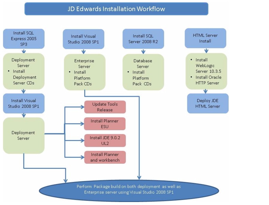
The following steps describe how to install Oracle JD Edwards on Cisco Unified Computing System (Figure 42).
Figure 42 JD Edwards Installation Workflow
JD Edwards Deployment Server Install
The steps to install the JD Edwards Deployment Server are described below.
Update all JDE machines with latest Windows 2008R2 patches and security fixes, since Microsoft routines issues hot fixes and patches that might positively impact security and performance.
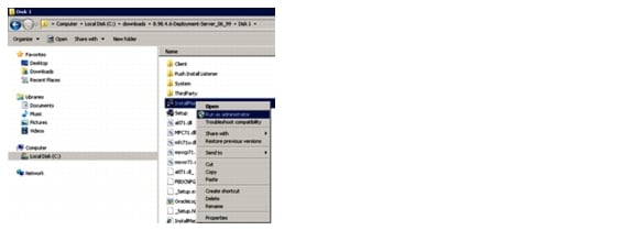
The Deployment server is used as a repository for JD Edwards installation and upgrade software and data artifacts. This section shows the steps to install the JD Edwards deployment server. The installation steps described are specific to the JD Edwards 9.0.2 application suite used in conjunction with JD Edwards tools release 8.98.4.6.
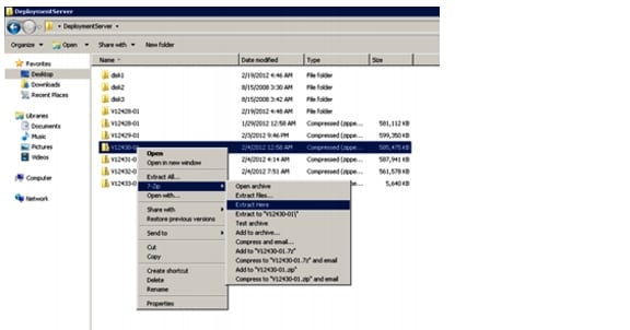
Download the Deployment Server binaries from Oracle eDelivery into a windows folder and extract the zip files in place using tools like Winzip or 7zip.
Perform the steps below, as referenced from Oracle solution ID: Document 1310036.1
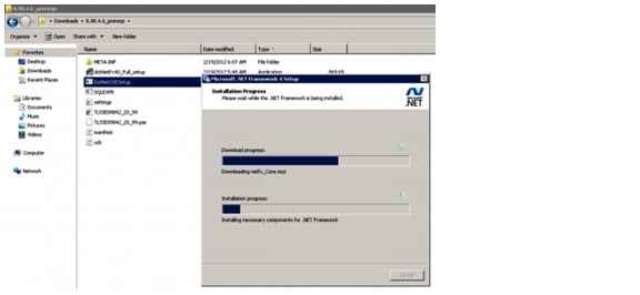
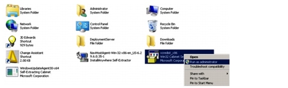
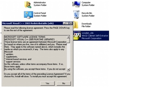
Download the installer for the database and the installer for the .NET Framework from Microsoft. In addition, you must follow these directions to download a program from Oracle that runs the two Microsoft installers, passing them parameters that EnterpriseOne needs to run properly.
Step 1
1.
2.
3.
4.
5.
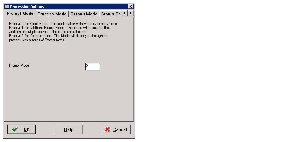
Step 2
1.
2.
3.
4.
5.
Step 3
1.
2.
Step 4
Step 5
Step 6
Step 7
Step 8
Step 9
Step 10
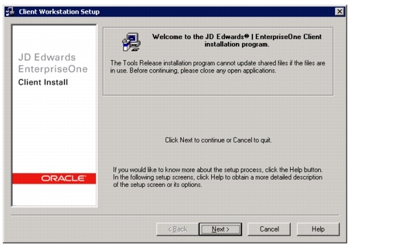
Wait for the deployment server to finish installing successfully.
Step 11
Step 12
Tools Upgrade on the Deployment Server
After the deployment server install finishes successfully, do a tools upgrade to 8.98.4.6. Download the appropriate tools release (8.98.4.6 deployment server in this case) from the Update center and run the installer as an administrator.
1.
2.
3.
Installing the Planner ESU
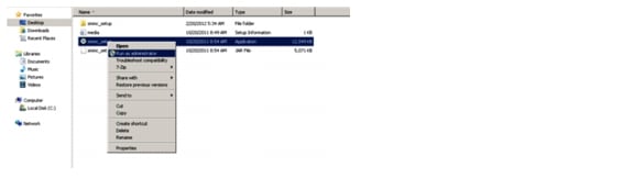
Download the appropriate planner ESU from Oracle update center onto the deployment server and unzip the contents. Run the executable as an administrator.
1.
2.
3.
4.
5.
6.
7.
8.
9.
10.
11.
12.
13.
14.
15.
16.
17.
18.
19.
20.
This completes the JD Edwards Deployment Server Installation.
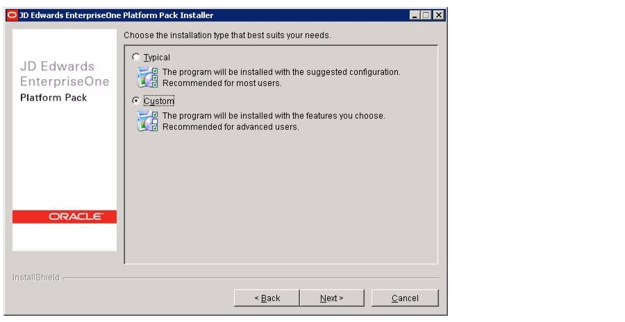
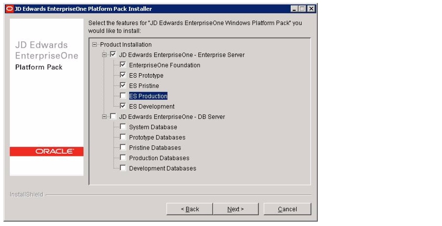
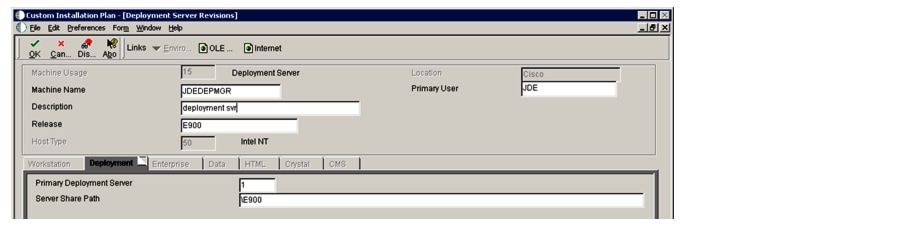
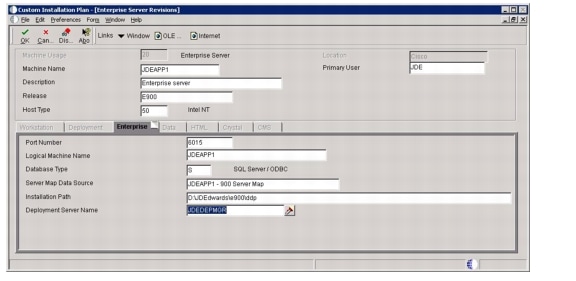
Installing the Enterprise Server
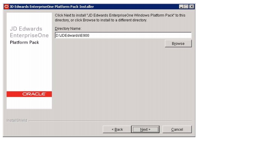
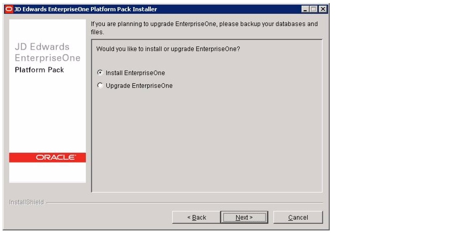
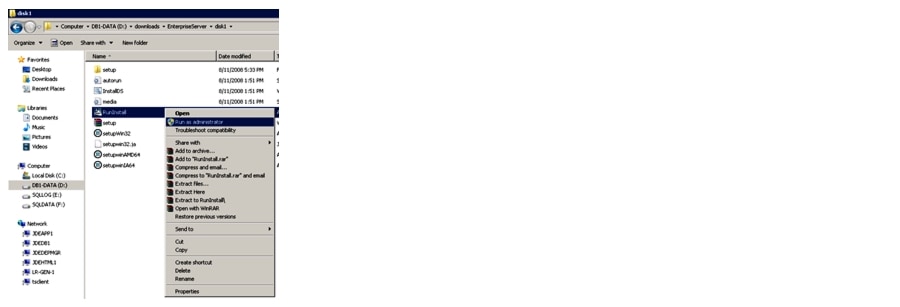
In our setup, the JDE Enterprise server and JDE database server are on different machines. The platform pack software pertaining to these two JDE servers has to be installed separately onto these two machines. Download the relevant platform pack software from Oracle eDelivery and extract its contents by unzipping the zip files. Please note that all zip files must be extracted in place within a folder as sub-folders disk1,disk2 etc.
1.
2.
3.
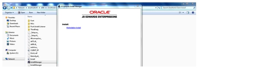
4.
5.
6.
7.
8.
9.
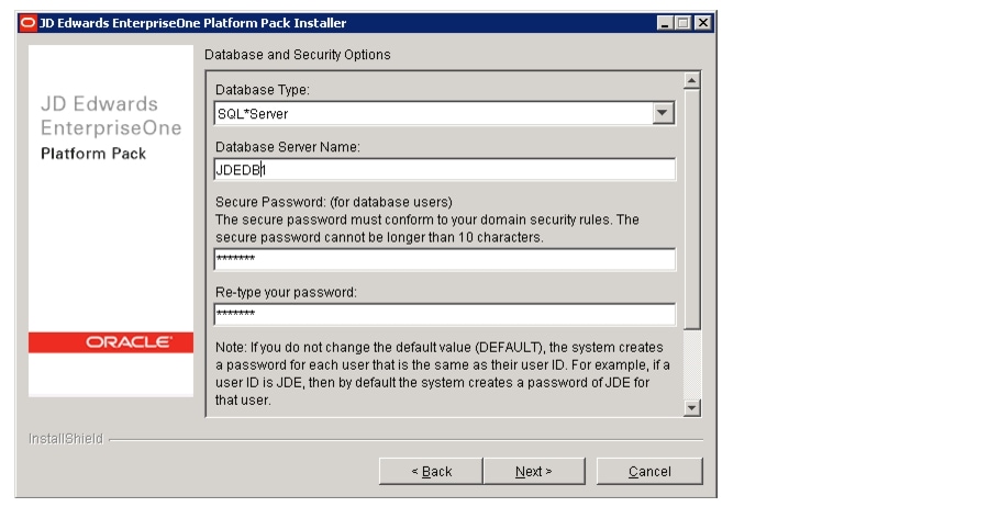
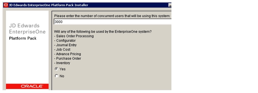
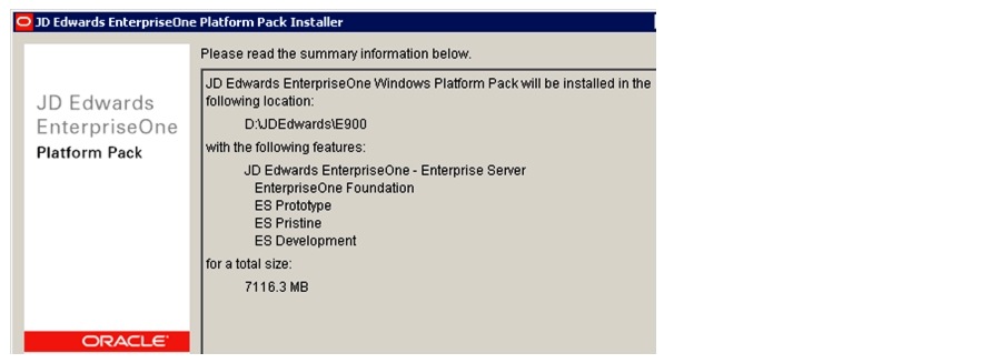
The selections used for installing the enterprise Server are summarized next.
The Enterprise server was successfully installed.
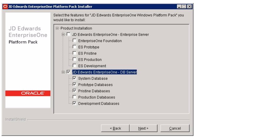
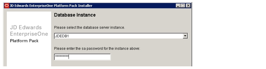
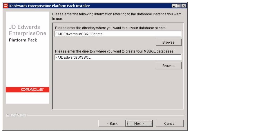
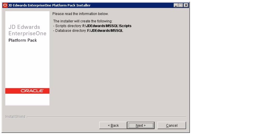
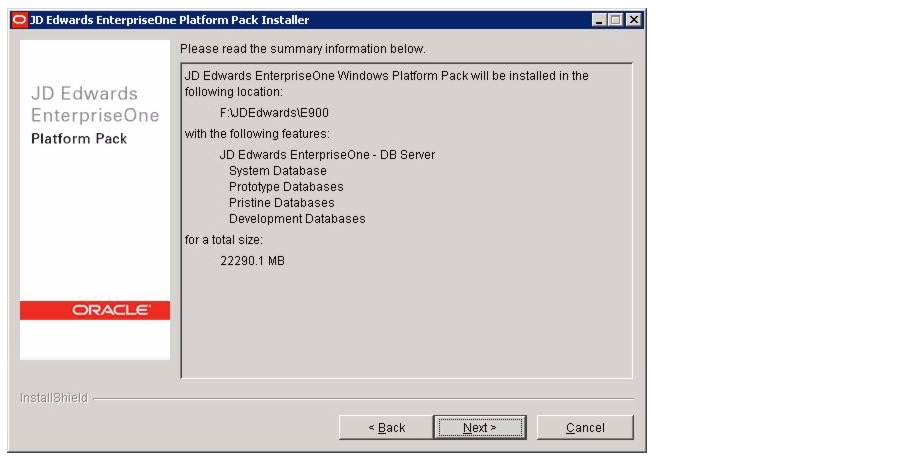
Installing the Database Server
To install Microsoft SQL Server 2008R2, refer to:
http://msdn.microsoft.com/en-us/library/bb500469%28v=sql.105%29.aspx
The Oracle support for solution document "64bit_MSSQL_EnterpriseOne_PlatformPack_WorkAround" was applied next.
1.
2.
3.
4.
5.
6.
7.
8.
9.
10.
The database platform pack is successfully installed. The Oracle solution ID 848317.1 "E900_SQL2008_Post_Installation_Batch_File_Install" was applied.
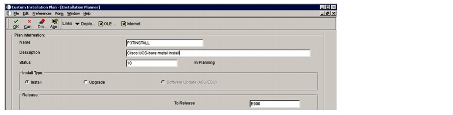
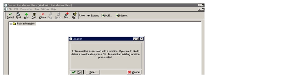
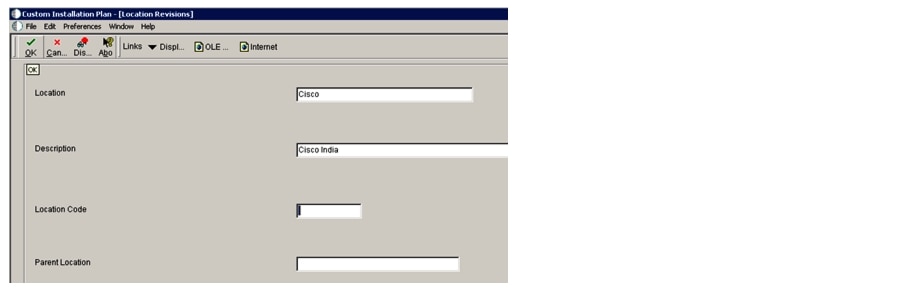
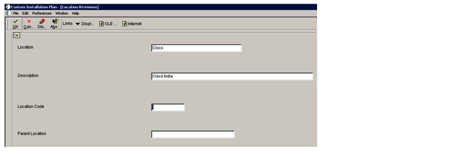
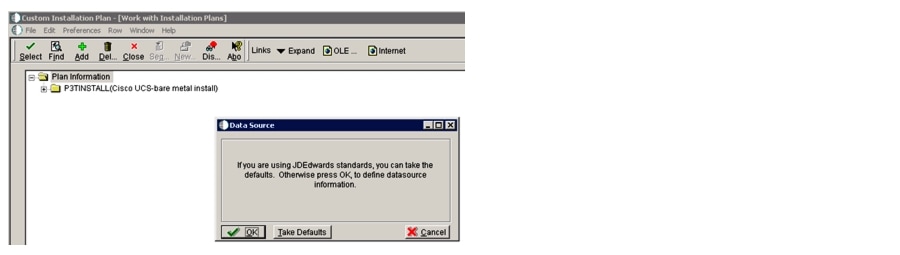
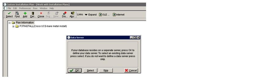
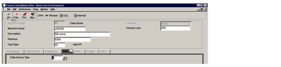
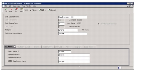
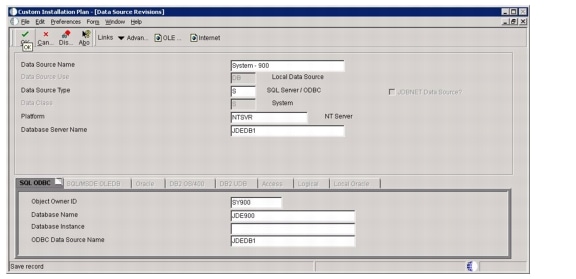
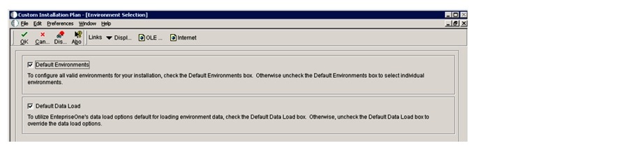
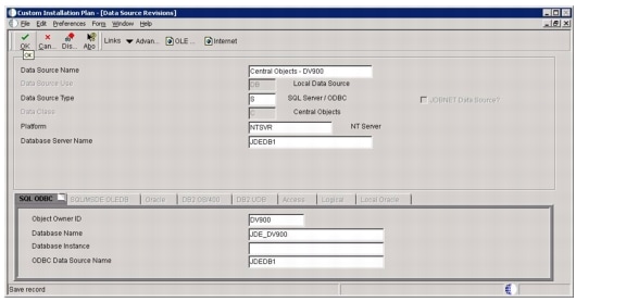
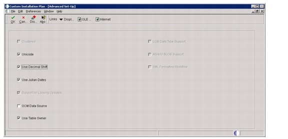
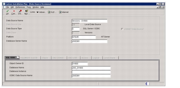
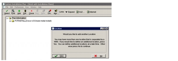
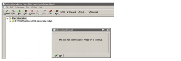
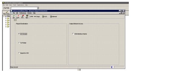
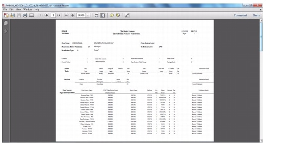
Installation Plan
1.
2.
3.
4.
5.
6.
7.
8.
9.
10.
11.
12.
13.
14.
15.
16.
17.
18.
19.
20.
21.
22.
23.
24.
25.
26.
27.
28.
29.
30.
31.
32.
Installation planner validation finished successfully.
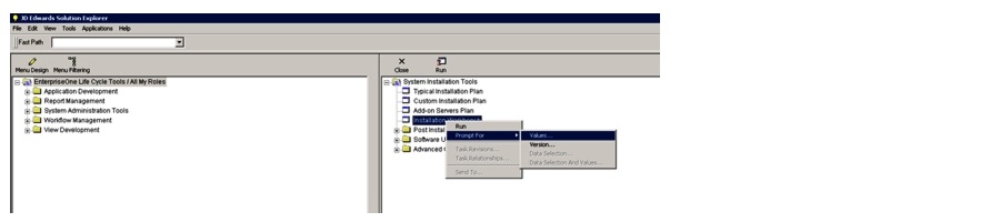
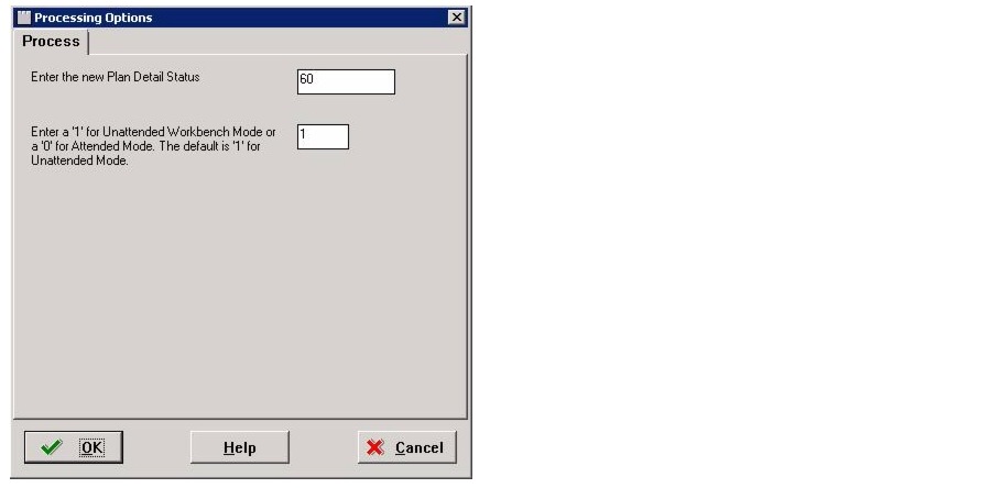
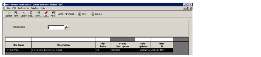
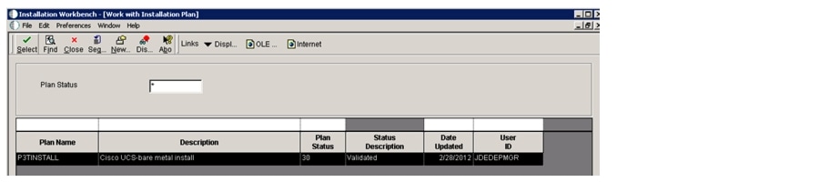
Installation Workbench
1.
2.
3.
4.
5.
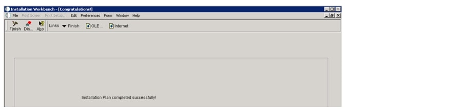
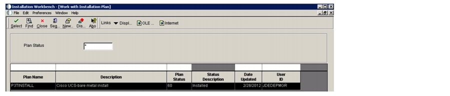
The plan status has changed from validated to installed.
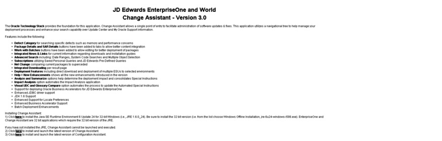
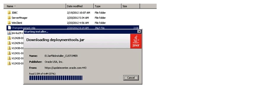
Change Assistant
Download the Change Assistant from Oracle updateCenter onto the Deployment Server.
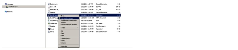
Installing the Change Assistant
Install the change assistant on the deployment server.
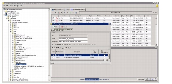
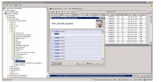
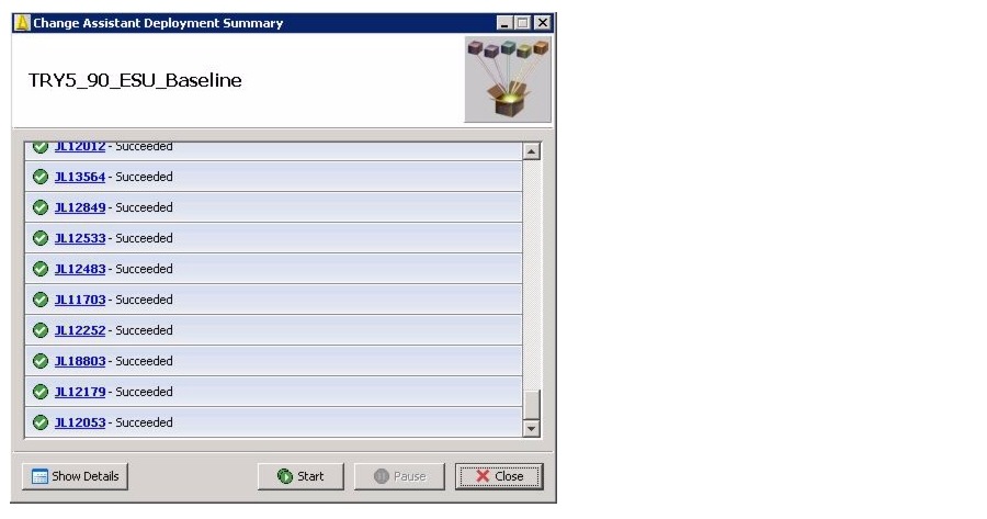
Installing the Baseline ESU
1.
2.
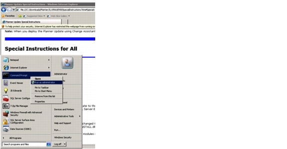
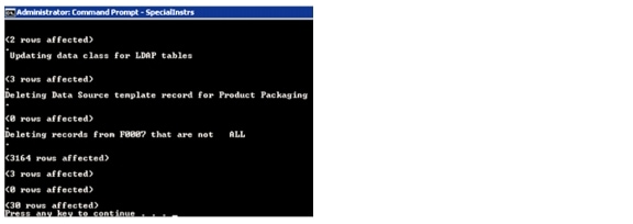
The baseline ESU application finished successfully. Apply the special instructions for the baseline ESUs. Some special instructions pertaining to localizations for specific countries might not be needed for your install, so it is essential to read through the special instructions.
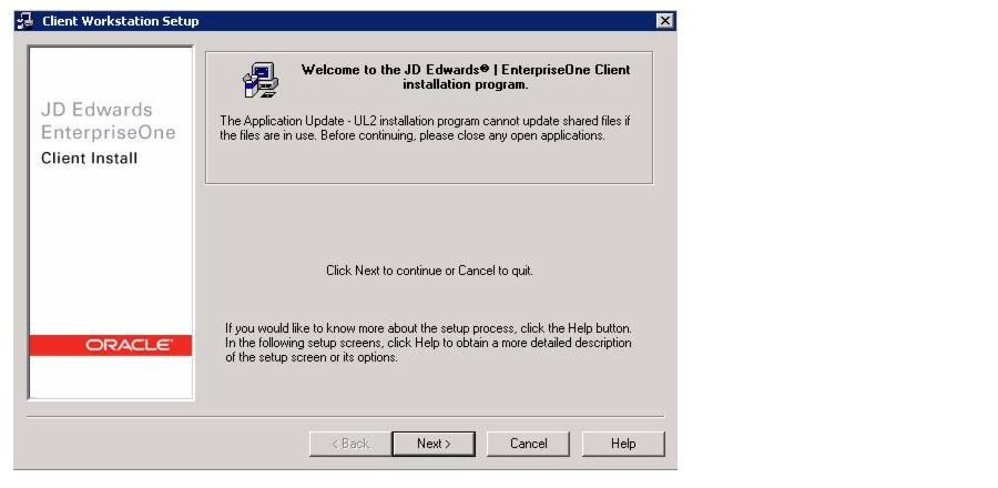
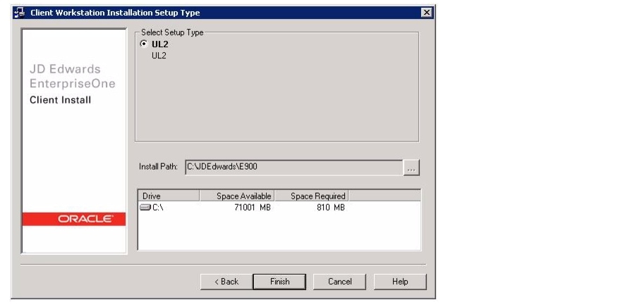
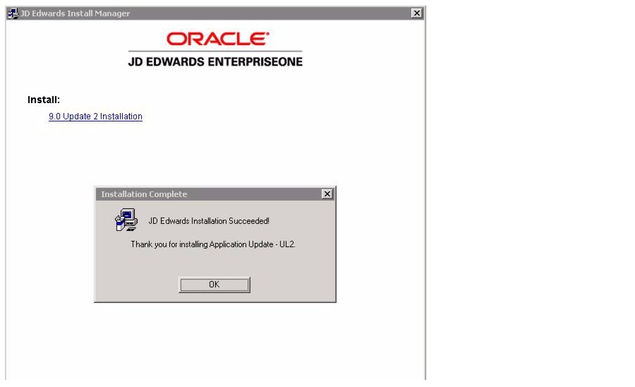
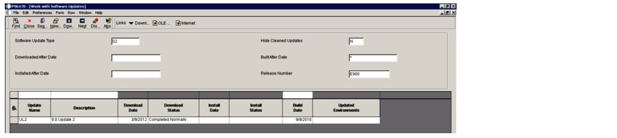
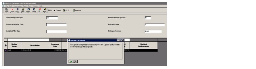
UL2 Install
The Oracle-JDE DIL kit requires the JDE application level to be set at 9.0 update level 2, so UL2 is applied to the installed base application. The UL2 file was downloaded from eDelivery and extracted through winzip. The RunInstall.exe is opened using run as admin.
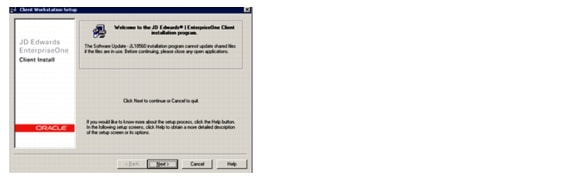
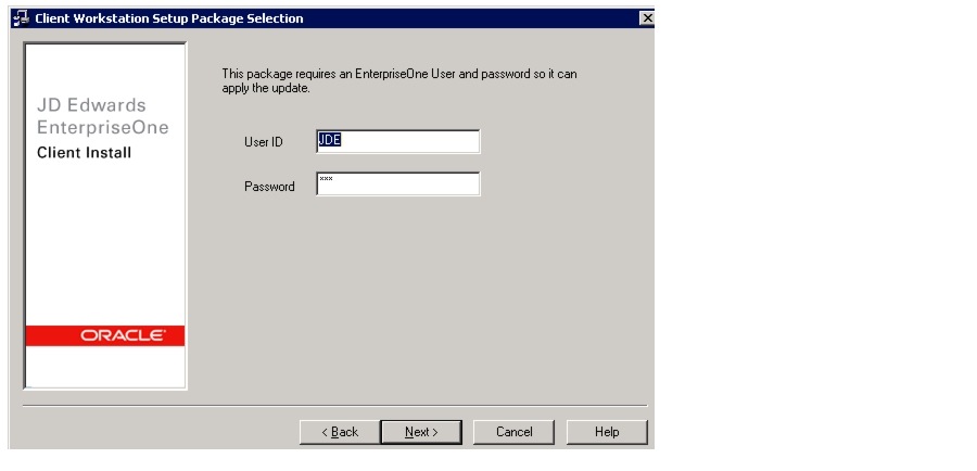
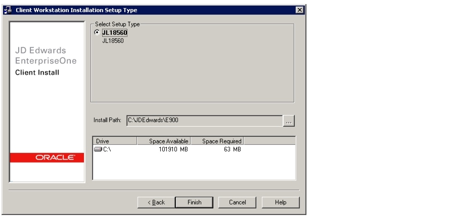
1.
2.
3.
UL2 is installed.
4.
Installing the Server Manager
1.
2.
3.
4.
5.
6.
The Server Manager is installed.
Installing the HTML Server
The Weblogic (WLS) 10.3.5 binaries were downloaded from Oracle eDelivery and the Weblogic Sever was installed on the HTML server. Please refer to the link below to install Oracle Weblogic Server 10.3.5
http://docs.oracle.com/cd/E21764_01/doc.1111/e14142.pdf
After installing the WLS, the following steps were performed to create a cluster on WLS and deploy JDE HTML server on it.
A domain was created. The admin server port was configured to be 7501 (default).
Configuring the Cluster
1.
2.
3.
4.
5.
6.
7.
The JDV900 environment was entered.
8.
Oracle HTTP Server Installation
The Oracle HTTP server is installed on the JDE HTML server.
Please refer to the links below to install Oracle JRF and Oracle HTTP server:
ADF/JRF: http://www.oracle.com/technetwork/developer-tools/adf/documentation/index.html
Oracle HTTP Server: http://docs.oracle.com/cd/E23943_01/doc.1111/e14260/overview.htm
Creating a JDE User
1.
2.
3.
4.
Oneworld user JDE is created.
5.
6.
7.
Installing the OneWorld Client
Use the shared location for client installation binaries on deployment server to install client on another machine.
1.
2.
The DV900FA package is chosen.
The client installation completed successfully.
Full Package Build
1.
2.
3.
4.
5.
6.
7.
8.
9.
10.
11.
12.
13.
14.
15.
The full package build usually takes between four to six hours to finish. Deploy the successfully built package on the enterprise server.
Summary
The previous sections detailed the approach taken for installing JD Edwards 9.0.2 on a physical N Tier Microsoft Windows environment. The benchmarking effort required the use of a weblogic cluster with an Oracle HTTP server front-end to load balance the users among the various cluster nodes. It is very important to check the Oracle support documents for information regarding the latest support statements in the various JDE MTRs as well as to check for recently released patches.
Oracle JD Edwards Performance and Scalability
Workload Description
The Oracle JD Edwards (JDE) Day in the life (DIL) kit is an attempt to capture how a typical customer interacts with the JDE system during the course of a typical day. The DIL kit accomplishes this with a set of scripts for 17 interactive applications as well as a set of JDE reports (UBEs) which processes a specific set of data which is part of the DIL database. Due to the availability of this standard set of scripts and UBEs, various hardware vendors, including Cisco have endeavored to characterize JDE implementations on their hardware platform to deliver a value proposition for prospective customers.
The DIL kit interactive application workload skews more towards SRM applications which feature prominently in the application workloads used by the large JDE customer base in the mid-scale manufacturing industry segment. The UBE workload is also representative of the type of reports that would be run by customers in this segment, though it does incorporate reports that cater to a larger audience of customers.
The DIL workload incorporates a good mix of applications ranging from multiple line item Sales Order and Purchase Order entries, coupled with light weight applications like supplier ledger enquiry. Similarly, the UBEs range from long running MRP processing and General Ledger Post reports to the short running Company constants and Business unit reports.
The LoadRunner scripts for the JDE interactive applications that the DIL kit incorporates measure the response times for certain key, representative transactions and these are incorporated in this whitepaper. The UBE performance is measured in terms of the total time taken to generate the report, as measured by timings within the JDE logs for those UBEs.
Test Methodology
The interactive and batch version of the JDE E1 DIL kit was run to capture the end-user response time variation and Batch execution rate with important system characteristics such as CPU, memory, and I/O across the test system. All four components of the JDE E1 deployment-HTML server, Enterprise Server for interactive user, Enterprise Server for Batch and Microsoft SQL database server-were monitored through Microsoft Windows Performance Monitor (PerfMon), a Microsoft Windows monitoring tool. EMC NAR files were also generated and analyzed to measure the IOPs generated on VNX5300.
Test Scenarios
Cisco invested considerable time and effort to test and execute a broad range of JDE applications scenarios to ensures that running the JDE DIL kit against a hardware configuration, closely mimics how a potential customer would use such a scenario. The documented response times and the best practices to deploy Oracle JDE E1 server would give customers a good indication on how they could expect such a configuration to perform when deployed in their production environments
Cisco endeavored to truly stress the hardware configuration, as well as provide customers with scenarios which provide a mix of interactive and batch processes running concurrently. Cisco devised various scenarios to test and record the impact of running a mixed batch workload would have on the interactive performance of JDE applications, since batch processes are typically resource hungry, thereby impacting the responsiveness of JDE interactive applications.
The elaborate test scenarios executed for JDE deployment on Cisco Unified Computing System are as follows:
1.
2.
3.
4.
5.
Interactive Workload Mix
The JDE E1 DIL kit is a set of 17 scripts that include Oracle SCM, SRM, HCM, CRM, and Financials applications.
Table 2 shows the transaction mix used for the JD Edwards interactive test with the JDE E1 DIL kit.
Table 5 Workload Mix
Interactive with Batch Test Scenario
In this scenario, Multiple LoadRunner configurations were created wherein the formulation and submission for execution of various short running UBEs, as listed in Appendix A were configured. These scenarios differed in the number of concurrent submissions of these UBEs as well as the frequency with which they were submitted. The scenarios reported encompass three different workloads, represented herein by the rate of report creation per minute.
For interactive and batch on same server, the first test iteration had a distribution of 67 UBEs/minute which were executed and completed for the duration of the LoadRunner run. In the second test iteration the rate of report creation was bumped up to 161 UBEs/minute and finally scaled to 305 UBEs/minute.
For interactive and batch on a separate server, the first scenario had a distribution of 73 UBEs/minute and completed for the duration of the LoadRunner run. In the second scenario the rate of report creation was bumped up to 151 UBEs/minute and finally scaled to 361 UBEs/minute.
In addition to the short running UBEs, four long running UBEs were part of each of the three test scenarios. The long running UBE processes chosen to be a part of the scenarios provided a sustained, database intensive load, thereby providing a reliable way for the test to measure interactive application performance during a period of high resource utilization.
Interactive workload Scaling
The test scenario for Interactive Scaling was executed to determine the variation in end-user response time in the event of increasing interactive users from 500 to 7500 concurrent users. The system resource utilization such as CPU, memory and disk IO was captured across all the three tiers i.e. HTML Server, JDE E1 Server and SQL Database server. To successfully scale to 7500 concurrent users, the physical memory of HTML and JDE E1 server installed on Cisco UCS B200 M2 server, was scaled from 96 GB (12 X 8 GB DIMMs) to 192 GB (12 X 16 GB DIMMs).
Figure 43 shows the weighted averaged response time for 500 to 7500 interactive users.
Figure 43 Oracle's JDE E1 DIL Kit Illustrating Weighted Average Response Time for Interactive Users
As illustrated in Figure 43, JDE E1 deployment on a Cisco UCS blade server infrastructure scales exceptionally well, with an almost flat response time of less than 0.2 second while scaling from 500 to 5000 concurrent users. At around 7500 concurrent users, weighted average response time is around 0.23 seconds, but is below the required threshold of 0.5 seconds for a DIL Kit benchmark.
User Response Time
User response time was captured at the LoadRunner Controller for all 17 interactive JDE E1 DIL test scripts. The five important JD Edwards applications measured using the JDE E1 DIL Kit were:
•
•
•
•
•
The transaction mix for these applications is detailed in the Workload Mix section of this document.
Figure 44 shows the weighted average response time for all 17 JDE E1 DIL kit scripts and for the five JD Edwards applications.
Figure 44 Oracle's JDE E1 DIL Kit Weighted Average Response Time
As detailed in Figure 44, the total weighted average response time for interactive user tests was always below 0.25 seconds during the scalability from 500 to 7500 concurrent users.
CPU Utilization
The HTML server and Enterprise Server were deployed on two discrete Cisco UCS B200 M2 Blade Servers and Microsoft SQL database server was deployed on a Cisco UCS B250 M2 Blade Server.
Figure 45 illustrates the average CPU utilization across the 3-Tier JD Edwards Technology Stack.
Figure 45 JDE E1 CPU Utilization
Observations
The maximum CPU utilization for JDE Enterprise Server was around 53 percent for 7500 interactive users.
CPU utilization was observed to be higher on the application tier than on the database tier. The database tier was around 18 percent for 7500 Interactive users which was relatively low as compared to HTML and JDE E1 Server.
The maximum CPU utilization recorded on HTML server was around 45%. This was on the expected line as multiple JVM instances configured with Oracle Weblogic Server and clustered through Oracle HTTP Server were running on a single Cisco UCS B200 M2 Server.
CPU utilization across all tiers gradually increased, as presented reflecting the linear scalability of the workload.
Memory Utilization
Memory utilization for the test with 500 to 7500 Interactive users across the 3-Tier JD Edwards technology stack is illustrated Figure 46.
The physical memory of JDE E1 and HTML servers deployed on Cisco UCS B200 M2 server, was increased from 96 GB memory to 192 GB memory to successfully run 7500 concurrent interactive users. Memory utilization on the Enterprise Server ranged from 13 to 91 GB, and on the HTML server memory utilization was approximately 12 to 145 GB. The Microsoft SQL database server deployed on the Cisco UCS B250 M2 Blade Server with 384 GB of memory was utilized ranging from 21 to 96 GB for a user workload of 500 to 7500 concurrent Interactive users.
Figure 46 JDE E1 Memory Utiliaztion
Observations
•
•
I/O Performance
The EMC VNX5300 was configured as the storage system for each of the three components of the JDE E1 deployment: HTML server, JDE E1 server, and Microsoft SQL database server. The Cisco UCS servers were booted from the SAN (EMC VNX5300), which allows unleashing of the full capabilities of Cisco UCS statelessness. Cisco UCS stateless configuration allows migration of Cisco UCS service profiles from a failed physical server to a standby server.
The Cisco UCS service profiles are logical representations of server configurations and infrastructure policies. Service profiles include all the firmware, firmware settings, and BIOS settings for server deployments (for example, definition of server connectivity, configuration, and server identity). Using service profiles, administrators can automate provisioning and increase business agility, enabling provisioning of server, network, and storage resources in minutes instead of days.
The Cisco UCS Manager, with its API, can also be configured for automated service profile migration during physical server hardware failure.
Figure 47 illustrates total disk I/O performance captured with the help of EMC NAR files, during the scalability test for 500 to 7500 JDE E1 interactive users.
Figure 47 JDE E1 Average IOPs on VNX5300
Observations
•
•
•
•
Individual UBEs
Batch processing is another critical activity in Oracle JD Edwards environment and it was important to test and determine the execution time for long running UBE processes. In real-world JD Edwards deployments, several long running UBEs are run after business hours, and they must complete within a fixed duration of time since they are end of day reports and should not spill over to the following day affecting interactive users. The performance characteristics of these UBEs are summarized in Table 6, with a brief description of what the reports do and what dataset they operate on. These long running reports ran on a fixed set of data with a standard set of processing options against the JDE DIL database, as described below.
Table 6 Long Running UBE Execution Time
Only Batch Execution
There are customers who run only JDE Batch processing for many business functions and it was imperative on Cisco to test and provide enough information for such customers to make an informed decision regarding their deployment of JDE on Cisco UCS. For such customers a test scenario was configured wherein, high volume of short running UBEs as well as four long running UBEs were executed, and the impact of running this test scenario was measured in terms of CPU and memory consumed on the Enterprise and Database server. This test scenario revealed that in the absence of a large number of concurrent interactive user loads, the JDE system can handle a lot more throughput in terms of UBE completions/minute.
The test successfully achieved 546 UBEs per minute. The average IOPS measure on the EMC VNX5300 was around 3800. It would be a good strategy for real-world JD Edwards customers, to schedule very high volume of UBEs during those non-peak hours when minimal interactive users are logged in to the JDE system.
Figure 48 illustrates the CPU and memory utilization on JDE Enterprise Server and SQL Database during the execution of Only Batch Processes.
Figure 48 Resource Utilization for Only Batch Execution
Interactive with Batch on same Physical Server
This scenario was executed to determine the effect on interactive user response time when a mix of short and four long running UBEs are executed in parallel, on the same JDE Enterprise Server.
The number of interactive applications users was fixed at 1000 users and various batch loads, ranging from low, medium and high were executed to measure the impact on Interactive application response times. The list of short and long running UBEs executed are detailed in Appendix A
User Response Time
As shown in Figure 49 the weighted average response time for 1000 concurrent interactive users was below 0.2 seconds for a batch load ranging from 67 UBEs per minute to 161 UBEs/min. No degradation of response time for UBE concurrent load of up to161 UBE per minute was noted. Response time increased marginally to 0.193 seconds for high UBE load of 305 UBEs/min, thus demonstrating the high performance capability of Cisco UCS B200 M2 server making it one of the best fits for JDE Enterprise Server deployment.
Figure 49 Weighted Average Response Time for 1000 User Interactive and Batch on Cisco UCS B200 M2 Server
CPU Utilization
Similar to previous test results, the HTML server and Enterprise Server were deployed on two discrete Cisco UCS B200 M2 Blade Servers. The Microsoft SQL database server was deployed on a Cisco UCS B250 M2 Blade Server.
Figure 50 illustrates the average CPU utilization across all the 3-Tier JD Edwards Technology Stack.
Figure 50 JDE E1 CPU Utilization for Batch and Interactive on the Same Server
Observations
The maximum average CPU utilization for JDE Enterprise Server was around 30% for 1000 users with high batch execution rate of 305 UBEs per minute.
The average CPU utilization on the database tier for low and medium UBE load was almost similar to previous test results at around seven to eight percent. Though it increased marginally to around 10.5percent for high batch workloads.
I/O Performance
Figure 51, illustrates the average IOPs recorded on EMC VNX5300. As mentioned earlier, EMC NAR files were analyzed to record the average IOPs for JDE deployment. There was minimal IO activity for HTML and Enterprise Server and SQL Server LDF and MDF files were the major contributor to the total IOPs.
Figure 51 Average IOPs on EMC VNX5300 for Batch and Interactive on the Same Server
Observations
The average IOPS generated on EMC VNX5300 for 1000 interactive users with no batch load was around 258 IOPS and it scaled to a maximum average of 2860 IOPS for 1000 users at a batch load of 305 UBEs per minute. This demonstrates that significant I/O activity was generated during concurrent batch and interactive user execution.
The response time observed from the EMC generated NAR files was less than five minutes for the duration of the test.
Interactive with Batch on Separate Physical Server
As a best practice, Cisco decided to execute a test scenario which would determine the effect of interactive user response time when executed with a mix of short and four long running UBEs, with JDE interactive server and JDE Batch Server deployed on two separate UCS B200 M2 Servers. The SQL Database was deployed on Cisco UCS B250 M2 server, was common to both JDE interactive and batch servers, thus maintaining same database schema for interactive and batch processes.
The number of interactive applications users was fixed at 5000 users and various batch loads, ranging from low, medium and high were run to measure impact on Interactive application response times.
Details on workload mix are elaborated under the section titled Interactive with Batch test Scenario.
User Response Time
As shown in Figure 52, the weighted average response time for 5000 concurrent interactive users was below 0.2 seconds for a batch load ranging from 73 UBEs/min to 151 UBEs per minute. There was minimal degradation observed in response time for UBE concurrent load of up to 151 UBE/minute. The high UBE load of 361 UBEs/min did have some effect on 5000 interactive user response time, which increased to 0.257 second. This is attributed to the fact that we have a common Database server for JDE interactive and batch server.
Figure 52 Response Time for 5000 Users With Batch on Separate Cisco UCS B200 M2 Servers
CPU Utilization
The HTML server, JDE Enterprise Server for interactive apps and JDE Enterprise Server for batch were deployed on separate Cisco UCS B200 M2 Blade Servers configured with two Intel Xeon X5690 processors. The Microsoft SQL database server was deployed on a Cisco UCS B250 M2 Blade Server configured with two Intel Xeon X5680 processors.
Figure 53 illustrates the average CPU utilization across all four JD Edwards tiers.
Figure 53 JDE E1 CPU Utilization for Interactive With Batch on Separate Cisco UCS B200 M2 Servers
Observations
Average CPU utilization on HTML Server and JDE Enterprise Server for interactive, remained almost steady throughout the test. This was expected, as the workload on the UBE batch server was the only one that was increased.
CPU utilization on SQL Database server increased from 12 percent with 5000 interactive users and no UBE load to around 35 percent with the same 5000 interactive users and a high UBE load of 361 UBEs per minute.
For low to medium batch load, the CPU utilization on JDE Batch Server varied from 10 percent to 20 percent, but at high UBE load of 361 UBEs/min the batch server was stressed with average CPU utilization at almost 50 percent.
Memory Utilization
In this test scenario, the batch server was deployed on a separate Cisco UCS B200 M2 which had the same physical memory configuration of 96 GB as used for the JDE Enterprise server for interactive and batch Server. Figure , illustrates the memory utilization for batch load with 5000 interactive users.
Figure 54 Memory Utilization for Interactive With Batch on Separate Physical Servers
Observations
As the batch server was deployed on a separate server and the interactive load was constant at 5000 users, it was an expected behavior that memory utilization of HTML Server and JDE Enterprise Server for interactive was almost same as that of 5000 users without UBE load.
Memory utilization on the SQL Database server increased to around 96 GB with low batch load of 73 UBEs/min and remained almost same for low to high batch load.
All through the various batch loads, the memory utilization on the batch server was just 10 percent to 14 percent of the total physical memory assigned.
I/O Performance
Figure 55, illustrates the total average IOPs measured on the EMC VNX5300 with the help of EMC NAR files.
Figure 55 Average IOPs on VNX5300 for Interactive With Batch on Separate Physical Servers
Observations
The number of I/O operations per second (IOPS) generated on the EMC VNX5300 increased from around 800 IOPs to 5600 IOPs for 5000 users with no batch to 5000 users with high batch load of 361 UBEs/min..
90-95 percent of total IOPs were generated from SQL Database Server. This is an expected behavior as the executed UBEs significantly stressed the LDF and MDF files of the database server.
The response time observed from the EMC generated NAR files was less than 5 ms for the duration of the test.
Best Practices and Tuning Recommendations
Oracle JD Edwards deployed on Cisco UCS with EMC Storage system was configured for medium to large scale ERP deployment. The benchmark of JDE DIL Kit demonstrated exceptional performance for JDE interactive users and JDE Batch processes both when executed in isolation as well as when run concurrently. The subsequent sections elaborate on the tuning parameters and best practices incorporated across hardware and software stack.
System Configuration
All the tests were executed using Cisco UCS B250 M2 as the Database server whereas the Enterprise and HTML servers were deployed on Cisco UCS B200 M2 servers.
Interactive and batch loads were split into two separate Cisco UCS B200 M2 machines for the scenario which had 5000 interactive users running concurrently with the batch process mix. For a lower load of Interactive users, both batch and interactive users were run on the same Cisco UCS B200M2 machine which hosted the JDE Enterprise server.
The memory on the Cisco UCS B200 M2 machines hosting the Enterprise and HTML servers was upgraded to 192 GB (12 * 16 GB DIMMs) for the high watermark 7500 Interactive user test. The memory operating speed remain to the maximum at 1333 MHz.
As the JDE Enterprise server running with high interactive users involves very high context switching, the CPU frequency of the JDE Application server and HTML Server was set to maximum. This can be achieved by setting the power plan on Microsoft Windows 2008 R2 to High Performance.
All the Cisco UCS Blade Servers were attached to a BIOS policy. BIOS policy is one of the features of Cisco UCS Service Profiles which enable users to incorporate similar BIOS settings all across the deployed servers. This helps a consistent configuration and the Administrators do not need to interrupt the boot process on each server to alter the BIOS setting. The BIOS policy configured for JDE deployment is elaborated below.
Figure 56
BIOS Setting s for CPU Performance
Figure 57 BIOS Settings for Physical Memory Performance
Microsoft SQL Server 2008 R2 Configuration
Several Settings were changed on SQLServer 2008 R2 to reflect the high load that the RDBMS was handling. Some of the important tuning parameters are elaborated below:
•
•
•
•
•
•
•
For more details on Disk layout and LUN layout for the SQL Server deployment, please refer Table 2. LUN Configuration for JD Edwards deployment & Figure 6. JD Edwards Disk Layout on EMC VNX5300.
WebLogic Server Configuration
The JRockit Java Virtual Machine (JVM) was used along with WebLogic 10.3.5. A vertical cluster of up to 40 JVMs was created and Oracle HTTP Server was used to load balance the load among the various nodes of the vertical cluster
Some of the important configuration details for the WebLogic Server are listed below:
•
•
•
•
•
JD Edwards Enterprise Server Configuration
The JD Edwards tools release 8.98.4.6 was used with JD Edwards application release 9.0.2. The number of interactive users per callobject peaked at around 18/callobject kernel.
Some of the important configuration settings for JDE initialization files are detailed below
•
–
–
–
–
–
•
–
–
–
–
–
–
–
–
–
•
–
–
–
–
–
–
–
–
–
–
•
–
–
–
–
–
–
•
–
–
–
–
–
Conclusion
This Cisco Validated Design demonstrates how Cisco UCS servers along with the latest EMC VNX storage technologies, form a highly reliable, robust solution for Oracle JDE Edwards implementation.
Enterprise Resource Planning (ERP) has been around for many decades and has provided agile IT practices to the Business. Organizations that have used the ERP Packages have immensely benefitted by streamlining their back end processes to improve management and improve ROI.
ERP being a business critical Application, takes a long time to implement and test; there is always a concern to move to newer technologies or experiment with the advanced features that are available today. Since this is a Business Critical Application, one of the most important concerns is predictability. Will it work for us, how it will work and at what cost?
Cisco has invested considerable time and effort to test, validate and characterize Oracle JD Edwards on Cisco UCS Platform using EMC VNX Storage, thus providing comprehensive scalable architecture and best practices. By leveraging the best practices and lessons learned in our extensive JDE benchmark activity, customers can confidently deploy JDE on Cisco UCS platform with EMC VNX storage and reduce risk.
Cisco Oracle Competency Center has provided considerable information in this document by testing and characterizing the Cisco UCS environment using the Oracle JD Edwards software stack. With the scalability demonstrated by the test results, Cisco is confident that these astounding results will prove that Cisco UCS and EMC VNX storage is a solid fit for any customer considering Oracle JD Edwards as their ERP platform
Bill of Materials
The Table 7 and Table 8 give details of all the hardware and software components used in this Cisco Validated Design.
Table 7 Component Description
Table 8 Software Details
Appendix A—Workload Mix for Batch and Interactive Test
Table 9 Batch Workload Mix
Table 10 JD Edwards Enterprise One Interactive Transactions
Appendix B—Reference Documents
•
•
•
•
•
Appendix C—Reference Links
The racking, power and installation of the chassis are described in the install guide: http://www.cisco.com/en/US/docs/unified_computing/ucs/hw/chassis/install/ucs5108_install.html
Cisco Unified Computing System CLI Configuration Guide: http://www.cisco.com/en/US/docs/unified_computing/ucs/sw/cli/config/guide/1.4/b_UCSM_CLI_Configuration_Guide_1_4.html
Cisco UCS Manager GUI configuration Guide: http://www.cisco.com/en/US/docs/unified_computing/ucs/sw/gui/config/guide/1.4/b_UCSM_GUI_Configuration_Guide_1_4.html
VP for Unified Storage System—A Detailed Review which is available at: http://www.emc.com/collateral/software/white-papers/h8058-fast-vp-unified-storage-wp.pdf
EMC FAST Cache—A Detailed Review which is available at: http://www.emc.com/collateral/software/white-papers/h8046-clariion-celerra-unified-fast-cache-wp.pdf
EMC FAST VP for Unified Storage System —A Detailed Review which is available at: http://www.emc.com/collateral/software/white-papers/h8058-fast-vp-unified-storage-wp.pdf
Additional information on EMC PowerPath/VE is available at: http://www.emc.com/collateral/software/data-sheet/l751-powerpath-ve-multipathing-ds.pdf
Additional information on the VNX Series is available at: http://www.emc.com/collateral/hardware/data-sheets/h8520-vnx-family-ds.pdf
Disclaimer
ALL DESIGNS, SPECIFICATIONS, STATEMENTS, INFORMATION, AND RECOMMENDATIONS (COLLECTIVELY, "DESIGNS") IN THIS MANUAL ARE PRESENTED "AS IS," WITH ALL FAULTS. CISCO AND ITS SUPPLIERS DISCLAIM ALL WARRANTIES, INCLUDING, WITHOUT LIMITATION, THE WARRANTY OF MERCHANTABILITY, FITNESS FOR A PARTICULAR PURPOSE AND NONINFRINGEMENT OR ARISING FROM A COURSE OF DEALING, USAGE, OR TRADE PRACTICE. IN NO EVENT SHALL CISCO OR ITS SUPPLIERS BE LIABLE FOR ANY INDIRECT, SPECIAL, CONSEQUENTIAL, OR INCIDENTAL DAMAGES, INCLUDING, WITHOUT LIMITATION, LOST PROFITS OR LOSS OR DAMAGE TO DATA ARISING OUT OF THE USE OR INABILITY TO USE THE DESIGNS, EVEN IF CISCO OR ITS SUPPLIERS HAVE BEEN ADVISED OF THE POSSIBILITY OF SUCH DAMAGES.
THE DESIGNS ARE SUBJECT TO CHANGE WITHOUT NOTICE. USERS ARE SOLELY RESPONSIBLE FOR THEIR APPLICATION OF THE DESIGNS. THE DESIGNS DO NOT CONSTITUTE THE TECHNICAL OR OTHER PROFESSIONAL ADVICE OF CISCO, ITS SUPPLIERS OR PARTNERS. USERS SHOULD CONSULT THEIR OWN TECHNICAL ADVISORS BEFORE IMPLEMENTING THE DESIGNS. RESULTS MAY VARY DEPENDING ON FACTORS NOT TESTED BY CISCO.
CCDE, CCENT, Cisco Eos, Cisco Lumin, Cisco Nexus, Cisco StadiumVision, Cisco TelePresence, Cisco WebEx, the Cisco logo, DCE, and Welcome to the Human Network are trademarks; Changing the Way We Work, Live, Play, and Learn and Cisco Store are service marks; and Access Registrar, Aironet, AsyncOS, Bringing the Meeting To You, Catalyst, CCDA, CCDP, CCIE, CCIP, CCNA, CCNP, CCSP, CCVP, Cisco, the Cisco Certified Internetwork Expert logo, Cisco IOS, Cisco Press, Cisco Systems, Cisco Systems Capital, the Cisco Systems logo, Cisco Unity, Collaboration Without Limitation, EtherFast, EtherSwitch, Event Center, Fast Step, Follow Me Browsing, FormShare, GigaDrive, HomeLink, Internet Quotient, IOS, iPhone, iQuick Study, IronPort, the IronPort logo, LightStream, Linksys, MediaTone, MeetingPlace, MeetingPlace Chime Sound, MGX, Networkers, Networking Academy, Network Registrar, PCNow, PIX, PowerPanels, ProConnect, ScriptShare, SenderBase, SMARTnet, Spectrum Expert, StackWise, The Fastest Way to Increase Your Internet Quotient, TransPath, WebEx, and the WebEx logo are registered trademarks of Cisco Systems, Inc. and/or its affiliates in the United States and certain other countries.
Building Architectures to Solve Business Problems
Oracle JD Edwards on Cisco Unified Computing
System with EMC VNX StorageLast Updated: April 20, 2013About Cisco Validated Design (CVD) Program
The CVD program consists of systems and solutions designed, tested, and documented to facilitate faster, more reliable, and more predictable customer deployments. For more information visit www.cisco.com/go/designzone.
ALL DESIGNS, SPECIFICATIONS, STATEMENTS, INFORMATION, AND RECOMMENDATIONS (COLLECTIVELY, "DESIGNS") IN THIS MANUAL ARE PRESENTED "AS IS," WITH ALL FAULTS. CISCO AND ITS SUPPLIERS DISCLAIM ALL WARRANTIES, INCLUDING, WITHOUT LIMITATION, THE WARRANTY OF MERCHANTABILITY, FITNESS FOR A PARTICULAR PURPOSE AND NONINFRINGEMENT OR ARISING FROM A COURSE OF DEALING, USAGE, OR TRADE PRACTICE. IN NO EVENT SHALL CISCO OR ITS SUPPLIERS BE LIABLE FOR ANY INDIRECT, SPECIAL, CONSEQUENTIAL, OR INCIDENTAL DAMAGES, INCLUDING, WITHOUT LIMITATION, LOST PROFITS OR LOSS OR DAMAGE TO DATA ARISING OUT OF THE USE OR INABILITY TO USE THE DESIGNS, EVEN IF CISCO OR ITS SUPPLIERS HAVE BEEN ADVISED OF THE POSSIBILITY OF SUCH DAMAGES.
THE DESIGNS ARE SUBJECT TO CHANGE WITHOUT NOTICE. USERS ARE SOLELY RESPONSIBLE FOR THEIR APPLICATION OF THE DESIGNS. THE DESIGNS DO NOT CONSTITUTE THE TECHNICAL OR OTHER PROFESSIONAL ADVICE OF CISCO, ITS SUPPLIERS OR PARTNERS. USERS SHOULD CONSULT THEIR OWN TECHNICAL ADVISORS BEFORE IMPLEMENTING THE DESIGNS. RESULTS MAY VARY DEPENDING ON FACTORS NOT TESTED BY CISCO.
CCDE, CCENT, Cisco Eos, Cisco Lumin, Cisco Nexus, Cisco StadiumVision, Cisco TelePresence, Cisco WebEx, the Cisco logo, DCE, and Welcome to the Human Network are trademarks; Changing the Way We Work, Live, Play, and Learn and Cisco Store are service marks; and Access Registrar, Aironet, AsyncOS, Bringing the Meeting To You, Catalyst, CCDA, CCDP, CCIE, CCIP, CCNA, CCNP, CCSP, CCVP, Cisco, the Cisco Certified Internetwork Expert logo, Cisco IOS, Cisco Press, Cisco Systems, Cisco Systems Capital, the Cisco Systems logo, Cisco Unity, Collaboration Without Limitation, EtherFast, EtherSwitch, Event Center, Fast Step, Follow Me Browsing, FormShare, GigaDrive, HomeLink, Internet Quotient, IOS, iPhone, iQuick Study, IronPort, the IronPort logo, LightStream, Linksys, MediaTone, MeetingPlace, MeetingPlace Chime Sound, MGX, Networkers, Networking Academy, Network Registrar, PCNow, PIX, PowerPanels, ProConnect, ScriptShare, SenderBase, SMARTnet, Spectrum Expert, StackWise, The Fastest Way to Increase Your Internet Quotient, TransPath, WebEx, and the WebEx logo are registered trademarks of Cisco Systems, Inc. and/or its affiliates in the United States and certain other countries.
All other trademarks mentioned in this document or website are the property of their respective owners. The use of the word partner does not imply a partnership relationship between Cisco and any other company. (0809R)
© 2012 Cisco Systems, Inc. All rights reserved
About the Authors
Anil Dhiman, Technical Marketing Engineer, Server Access Virtualization Business Unit, Cisco Systems, Inc.
Anil has over 12 years of experience in benchmarking and performance analysis of large multi-tier systems such as Foreign Exchange products. Anil specializes in optimizing and tuning of applications deployed on J2EE application servers and has delivered world record numbers for SPECjbb2005 benchmarks on Cisco Unified Computing Systems. Anil has worked as a performance engineer for Oracle IAS team. Prior to joining Cisco, Anil worked as a performance engineering architect with Symphony Services.
Shankar Govindan, Technical Marketing Engineer, Server Access Virtualization Business Unit, Cisco Systems, Inc.
Shankar has over 20 years of experience in IT and over 15 years in the Oracle Consulting space working on projects for large corporations such as , Syntel; Daimler Chrysler; Humana; Conway; Mastech London; SBC Plc, London; BPL India; Enron; Xerox; Jubitz; ACTA; Portland General Electric; CNF; LSI; and Dell. Before joining Cisco, Shankar worked for the Dell Solutions Engineering team as reference architecture and sizing expert.
Acknowledgements
For their support and contribution to the design, validation, and creation of this Cisco Validated Design, we would like to thank:
Vadiraja Bhatt—Cisco
Amar Venkatesh—Cisco
Ramesh Chitor—Cisco
John McCabel—Cisco
Kathy Sharp—EMC
Radhakrishnan Manga—EMC