Feedback
Table Of Contents
Configuration Rules for Populating Cards in the MGX 8230
Changing a Single-Height Card Slot to a Double-Height Card Slot
AC Power Cords Available for Different Regions
Power Consumption of the Different MGX 8230 Modules
MGX 8230 System Current Requirement
Heat Dissipation for a Fully Loaded MGX 8230
Card Cage and Midplane Architecture
Midplane Functional Description
Mechanical
This section describes the mechanical design of the MGX 8230, including chassis, power options, midplane, cabling, and EMI.
Chassis
The MGX 8230 is a 14-slot chassis with horizontally mounted processor modules, service modules, and back cards:
•
Two double-height slots are dedicated for the PXM1 modules.
•
•
Slots are numbered 1 to 7 on the left half of the chassis, and 8 to 14 on the right side of the chassis.
Note
Since front slots 1 and 2 are always double-height for PXM1 processor modules, slots 8 and 9 refer only to the back card slots that correspond to the two lower single-height slots on the left side of the chassis as seen from the rear.
When a double-height front card is installed, the left slot number is used. The back cards are numbered according to the front card numbering scheme, with the exception of slots 8 and 9 as noted above.
•
•
•
For information on converting single-height slots, see the "Changing a Single-Height Card Slot to a Double-Height Card Slot" section.
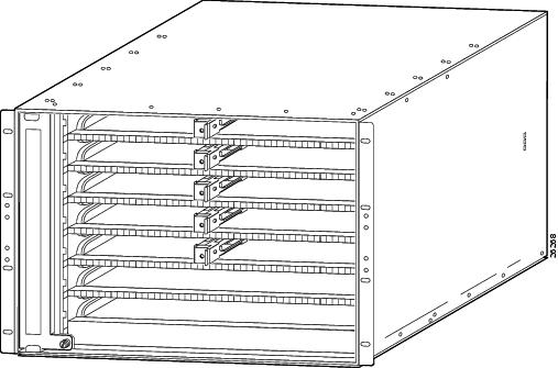
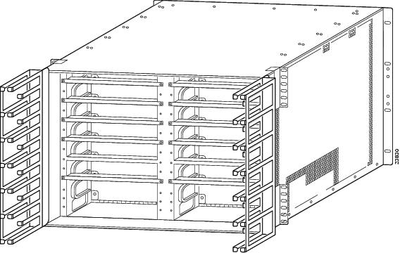
The MGX 8230 chassis is 17.72 inches wide, 12.25 inches high (14.00 inches high with optional AC Power Tray), and 23.5 inches deep. The chassis can be mounted in either a 19-inch or a 23-inch EIA/RETMA and ETSI racks. Figure 2-3 illustrates the different sections of the MGX 8230 chassis.
Figure 2-1 MGX 8230 Card Cage—Front View
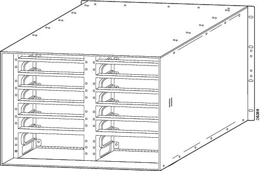
Figure 2-2 MGX 8230 Card Cage—Rear View
Configuration Rules for Populating Cards in the MGX 8230
The following rules and guidelines are to assist the user in installing single-height and double-height service modules in an MGX 8230 chassis. Rules must be followed while guidelines are instituted for better performance.
Changing a Single-Height Card Slot to a Double-Height Card Slot
The MGX 8230 is typically configured at the factory as you ordered it. Unused card slots are configured for single-height modules and covered with blank faceplates.
Single-height service module slots 3-7 and 10-14 can be converted into double-height slots by removing the center divider module.
Note
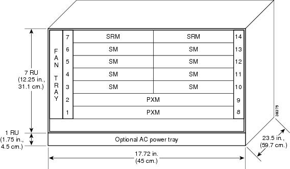
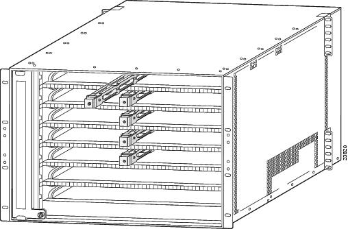
Figure 2-3 illustrates the slot numbering of an MGX 8230 with slot 3 configured for a double-height module.
Figure 2-3 MGX 8230 Slot Configuration
Note
•
•
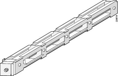
Figure 2-4 Center Guide Module—Slot Divider
Figure 2-5 Front View of an MGX 8230 Card Cage
Card Dimensions
Table 2-1 shows the physical characteristics for modules supported on the MGX 8230.
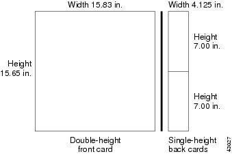
Figure 2-6 is an illustration of the Double-Height Card Dimensions.
Figure 2-6 Double-Height Card Dimensions
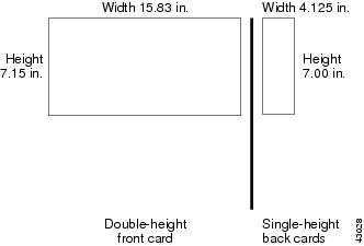
Figure 2-7 is an illustration of the Single-Height Card Dimensions.
Figure 2-7 Single-Height Card Dimensions
Optical Specifications
Table 2-2 provides the optical specifications for the different interfaces.
As the optical transceivers in the PXM1 interfaces are compliant with ITU-T G.957, the dispersion tolerance according to G.957 are:
•
•
•
•
The modulation used in all PXM1 optics is direct build-in electroabsortion modulator in standard temperature range (0 - 70°C).
The type of laser sources for the different PXM1 interfaces are
•
•
•
•
All MGX single mode optical interfaces (OC-3, OC-12, and OC-48) are terminated with the UPC (Ultra Physical Contact) polish type. Note that this does not apply to multimode fiber. The UPC polish includes an extended polishing cycle at the end-face surface for a better surface finish, resulting in back reflection as low as -55 dB.
Interface Ranges
The supported cable distance ranges are shown in the following list.
1.
2.
3.
4.
MGX 8230 Power
The MGX 8230 power system is designed with distributed power architecture centered around a -48 VDC bus on the system backplane. The -48 VDC bus accepts redundant DC power from either a -42 to -56 VDC source via optional DC power entry modules (PEMs) or from a 100 to 120, or a 200 to 240, VAC source via the optional AC Power Supply Tray. The MGX 8230 backplane distributes power via connectors on the -48 VDC bus to each hot-pluggable processor or service module. Each card incorporates on-board DC-DC converters to convert the -48 VDC from the distribution bus voltage to the voltages required on the card.
Optional AC Power Supply
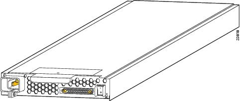
For an AC-powered MGX 8230, an optional AC power supply tray is attached to the bottom of the 8230 card cage at the factory. The AC power supply tray is 1 rack-unit high, and can hold up to two AC Power Supply modules. Each AC Power Supply module can provide up to 1200W at 48VDC and has its own AC power cord and power switch. Figure 9 shows the rear view of an optional AC Power Supply module. The power supplies can be configured as 1+1 redundant. If no redundancy is desired, an AC tray with one AC power supply and one AC power cord can also be ordered.
Figure 2-8 AC Power Supply Module—Rear View
Each AC Power Supply Module incorporates the following features:
•
•
•
•
•
•
•
DC-Power
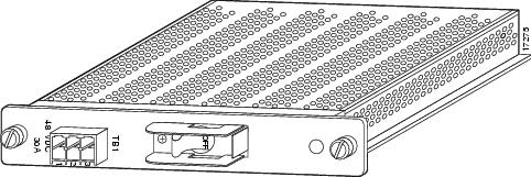
For DC systems, a DC Power Entry Module (PEM) is required for each DC source of central office power -42 to -56 VDC. The MGX 8230 can support two DC power sources and has rear panel slots for two DC PEMS. Figure 2-9 illustrates a DC PEM.
The DC PEMs incorporate the following features:
•
•
•
Figure 2-9 MGX 8230 DC Power Entry Module
AC Power Cords Available for Different Regions
The following chart details the AC power cords available by regions.
Power Consumption of the Different MGX 8230 Modules
The power consumption of the different modules is defined in Table 2-4.
MGX 8230 System Current Requirement
The current requirements are configuration-dependent. For general planning purposes use
48VDC, Current rating: 25 AMP
Note
Heat Dissipation for a Fully Loaded MGX 8230
A fully loaded, AC powered MGX 8230 dissipates up to 4800 Btus. A DC powered MGX 8230 dissipates up to 4100 Btus.
Safety Switches
The MGX 8230 does not use circuit breakers instead of switches or magnetic conductors. These circuit breakers are compliant with VDE and IEC 950 specifications.
Circuit Breakers
For an AC-powered MGX 8230, verify that the shelf's power comes from dedicated AC branch circuits. The circuits must be protected by a dedicated, 15 amp circuit breaker. Cisco Systems recommends that the site has a 15 amp AC circuit breaker with a long trip-delay at each branch circuit.
For a DC-powered MGX 8230, verify that its power comes from a dedicated DC branch circuit. This branch circuit must be protected by a dedicated circuit breaker. Cisco Systems recommends that the site has a dedicated 30 amp circuit breaker with a medium trip delay at each branch circuit. A DC-powered MGX 8230 uses a 30 amp circuit breaker with a short trip delay on each -48V input.
Cooling
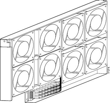
The MGX 8230 incorporates a fan tray assembly (with eight fans) located on the left side of the card cage to pull ambient cooling air into the system through openings between front card faceplates, over the boards in the card cage, and out through air exhaust openings on the left side of unit.
Figure 2-10 is an illustration of the MGX 8230 fan tray assembly.
The cooling system incorporates the following design features:
•
•
•
•
The PXMs provide a variety of system environmental monitoring and logging functions. The PXM is capable of reading the speed of these fans to determine if they are operating below the configured threshold. Upon failure of any of the fans, an alarm is generated. The temperature monitor circuit monitors the MGX 8230 shelf air-intake temperature in units of one degree Celsius.
Figure 2-10 MGX 8230 Fan Tray Assembly
Environmental
MGX 8230 environmental specifications are listed as follows.
•
–
–
–
•
–
•
–
•
–
•
–
•
–
•
–
Electromagnetic Interference
To maintain correct airflow and to reduce Radio Frequency Interference (RFI) and Electromagnetic Interference (EMI), all unused back card slots must be covered with the blank faceplates provided by Cisco Systems. If a front door option is ordered, there is no need to order or install blank front faceplates.
Front side EMI is obtained by either installing Cisco provided blank cards or by installing an EMI-tight front door, which can be ordered as an option. There will be different faceplates to accommodate double-height and single-height slots.
Card Cage and Midplane Architecture
The MGX 8230 chassis has two dedicated slots for the PXM1, eight single-height slots (four double-height slots) for service modules, and two single-height slots for SRMs.
Midplane Functional Description
The MGX 8230 has a midplane design that increases flexibility and minimizes service disruptions by allowing front cards to be replaced without disrupting cabling at the rear of the chassis. In backplane architectures, the design reduces the flexibility to change interfaces and increases the risk of causing accidental operational outages due to cables coming loose when cards are being swapped.
Midplane Key Benefits
The benefits of the midplane design are as follows.
•
•
Backplane Components
Components of the backplane include:
•
•
•
•
•
Cell Buse Artchitecture
The MGX 8230 architecture is built around the switching fabric on the processor switching module, the backplane, and the service modules.
The main function of the MGX 8230 backplane is to connect cards together, terminate critical signals properly, provide -48 VDC power to all cards, and set ID numbers for each slot. In addition, the
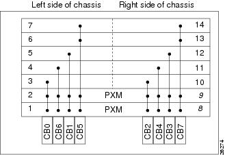
MGX 8230 backplane interconnects both front cards and back cards together via pass-through connectors.The cell bus provides high-speed interface between the switch fabric and the service modules. Figure 2-11 shows the overall cell bus distribution of the backplane.
Each PXM supports eight master cell buses and one slave cell bus connected to the backplane. The service modules have two slave cell bus ports, one from each PXM.
A cell bus is comprised of a group of signals used to transfer data between the PXM and a service module. CB 0, 6, 1, 2, 4, and 3 are dedicated to physical slots 3, 4, 5, and 10, 11, and 12 respectively, which support high-speed service modules. CB5 supports physical slots 6 and 7, and CB7 supports physical slots 13 and 14, as well as the alternate PXM's slave port.
There is a connection on cell bus 7 to the alternate PXM. A PXM is able to communicate with the other PXM using the slave cell bus port on that card. Slots 8 and 9 only refer to back card slots.
Figure 2-11 shows the interconnection of the cell bus lanes on the midplane.
Figure 2-11 MGX 8230 Cell Bus Lane Interconnection
Distribution Bus
The MGX 8230 backplane supports the same distribution bus employed in the MGX 8220. This is used in conjunction with the SRM-3T3 to provide M13 circuit breakout and distribution capability as well as T1/E1 1:N service module redundancy (in bulk mode the service modules have 1:N redundancy without using the separate T1 redundancy bus). The distribution system is also augmented with a T3 distribution mechanism, so that a future SRM could break out an OC-12 into DS3 streams, which in turn could be routed to individual DS3 speed service modules. The TDM distribution buses for the upper and lower service bays are independent. In the future, the SRM may also be required to break out traffic to the DS0 level in order to provide more advanced grooming/pooling capabilities.
Service Redundancy Bus
A redundancy bus supports T1/E1 service module redundancy. The service modules have access to the redundant bus, and the service redundant logic on the SRM is responsible for sending control signals to each service modules to use the redundant bus. This redundancy bus carries traffic from the back card of a failed service module to the front card of an active secondary card module.
Local Bus
The local bus is the core card bus that connects the PXM and SRM cards.
BERT Bus
The BERT bus is used by the SRM-3T3/C to distribute T1 signals to the service modules. The SRM can support BERT on only one line or port at a time. BERT is capable of generating a variety of test patterns, including all ones, all zeros, alternate one zero, double alternate one zero, 223-1, 220-1, 215-1, 211-1, 29-1, 1 in 8, 1 in 24, DDS1, DDS2, DDS3, DDS4, and DDS5.
The BERT bus is used to provide the BERT operation to the individual service modules. This bus is also used to drive special codes such as fractional T1 loopback codes, and so on, onto the T1 line. The BERT function is initiated on ONLY one logical T1/E1 Nx64K port per MGX 8230 at any given time and this is controlled by the PXM. The SRM-3T3 ensures that the BERT patterns are generated and monitored (if applicable) at the appropriate time slots.
The data path then for that particular port (n x 64K) is from the service module to the SRM-3T3/C (via the BERT bus) and back to the service module (via the BERT bus). On the service module, the data that is transmitted is switched between the regular data and the BERT data at the appropriate timeslots as needed. Similarly in the receive direction, the received data is diverted to the BERT logic for comparison during appropriate time slots.
The BERT logic is self synchronizing to the expected data. It also reports the number of errors for bit error rate calculation purposes.
Caution
Cable Management
The following cables are required for minimum configuration of one MGX 8230 shelf:
•
•
For systems sold in the United States, the AC power is supplied through standard IEC power cord. Power cords for different countries can be ordered through Cisco.
Additionally, the system also requires the following cables under different configurations.
•
•
MGX 8230 Cable Management
A fully loaded MGX 8230 may have many cables attached to the rack's modules. Cable management kits are available for installation on the rear of rack modules. These kits provide the means to route the power and data cables in a neat and orderly fashion to and from the modules in the shelf. The cable-management system is shipped with attaching hardware along with your MGX 8230. Install the cable-management brackets after a rack-mounted unit has been installed in a rack, or a standalone MGX 8230 has been positioned.
Figure 2-12 illustrates an installed cable management system. When installing the cable-management system on a rack-mount MGX 8230, the screws securing cable guides to the shelf chassis are inserted from the outside into the captive nuts in the chassis. When installing the cable-management system in a standalone MGX 8230, the screws securing cable guides to the shelf chassis are inserted from the outside to the captive nuts in the chassis.
Figure 2-12 Cable Management Assembly at Back Enclosure
The cable-management system provides the following features:
•
•
•