Feedback
Table Of Contents
Preparing for Network Connections
Connecting the Console Port to a PC
Connecting the 10/100 Ethernet Management Port
Connecting to the MGMT 10/100/1000 Ethernet Port
Using the Switch Setup Utility
Initial Switch Configuration
This chapter provides instructions for setting up the hardware, connecting to the console port, and initially configuring the switch.
This chapter includes the following sections:
•
Preparing for Network Connections
•
•
•
Preparing for Network Connections
When preparing your site for network connections to the Andiamo 9500 switch, consider the following for each type of interface:
•
•
•
Before installing the device, have all additional external equipment and cables available.
Configuration Prerequisites
Before you configure a switch in the Cisco MDS 9000 Family for the first time, make sure you have the following information:
•
•
•
•
•
Connecting the Console Port
This section describes how to connect the RS-232 console port to a PC. The console port allows you to perform the following functions:
•
•
•
•
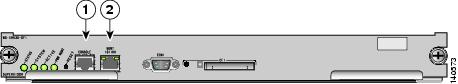
Figure 2-1, Figure 2-3, Figure 2-4, and Figure 2-4 show the console port and the management port, located on a Cisco MDS 9500 series supervisor-1 module, Cisco MDS 9500 series supervisor-2 module, a Cisco MDS 9200 Series supervisor module, and Cisco MDS 9100 Series supervisor module.
Figure 2-1 Cisco MDS 9500 Series Supervisor-1 Module
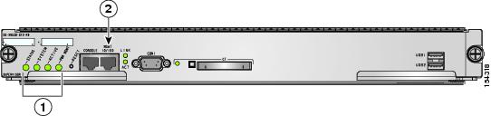
Figure 2-2 Cisco MDS 9500 Series Supervisor-2 Module
Status, System, Active, and Pwr Mgmt LEDs
MGMT 10/100/1000 Ethernet port (with integrated Link and Activity LEDs)
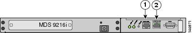
Figure 2-3 Connecting the Console Cable to a Cisco MDS 9200 Series Switch
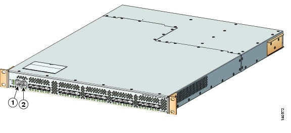
Figure 2-4 Connecting the Console Cable to a Cisco MDS 9100 Series Switch
Connecting the Console Port to a PC
You can connect the console port to a PC serial port for local administrative access to the Andiamo 9500 switch.
Note
To connect the console port to a PC, follow these steps:
Step 1
•
•
•
•
Note
switch# config t
switch(config)# no flush-at-activation
switch(config)# exit
switch# copy running-config startup-config
This configuration ensures that the MDS switch does not receive random characters that might cause it to hang.Step 2
Step 3
Note
Connecting the 10/100 Ethernet Management Port
The autosensing 10/100 Ethernet management port is located on the left side of the front panel (labeled 10/100 MGMT), to the right of the Console port (see Figure 2-1, Figure 2-4, and Figure 2-4). This port is used for out-of-band management of the Cisco MDS 9000 Family switches.
Make sure to connect the Ethernet management ports of both supervisor modules on an MDS 9500 Series switch. Even though there are two Ethernet connections, only one management IP address is required for a switch with dual supervisors.
Tip
If only the active supervisor module is connected to the LAN and an event occurs that causes a system switchover (such as a software upgrade), the switch becomes unmanageable through the Ethernet port after the active supervisor reboots and the standby supervisor becomes the active supervisor.
Use modular, RJ-45 cables to connect the 10/100 Ethernet management port to external hubs and switches.
Connecting to the MGMT 10/100/1000 Ethernet Port
The Supervisor-2 module supports an autosensing MGMT 10/100/1000 Ethernet port (labeled "MGMT 10/100/1000") and has an RJ-45 interface. You can use this port to access and manage the switch by IP address, such as through Cisco Fabric Manager.
Use a modular, RJ-45, straight-through UTP cable to connect the MGMT 10/100/1000 Ethernet port to an Ethernet switch port or hub.
Using the Switch Setup Utility
The switch setup utility helps you configure the switch. To configure the switch, follow these steps:
Step 1
•
•
Refer to the hardware installation guide for your specific product.
Tip
Step 2
Step 3
Note
After powering on the switch, you see the following output:
General Software Firmbase[r] SMM Kernel 1.1.1002 Aug  6 2003 22:19:14 Copyright (C) 2002
General Software, Inc.
Firmbase initialized.00000589K Low Memory Passed01042304K Ext Memory PassedWait.....General Software Pentium III Embedded BIOS 2000 (tm) Revision 1.1.(0)(C) 2002 General Software, Inc.ware, Inc.Pentium III-1.1-6E69-AA6E+------------------------------------------------------------------------------+| System BIOS Configuration, (C) 2002 General Software, Inc. |+---------------------------------------+--------------------------------------+| System CPU : Pentium III | Low Memory : 630KB || Coprocessor : Enabled | Extended Memory : 1018MB || Embedded BIOS Date : 10/24/03 | ROM Shadowing : Enabled |+---------------------------------------+--------------------------------------+Loader Loading stage1.5.Loader loading, please wait...Auto booting bootflash:/m9500-sf1ek9-kickstart-mz.2.1.1a.bin bootflash:/m9500-s f1ek9-mz.2.1.1a.bin...Booting kickstart image: bootflash:/m9500-sf1ek9-kickstart-mz.2.1.1a.bin...................Image verification OKStarting kernel...INIT: version 2.78 bootingChecking all filesystems..... done.Loading system softwareUncompressing system image: bootflash:/m9500-sf1ek9-mz.2.1.1a.binCCCCCCCCCCCCCCCCCCCCCCCCCCCCCCCCCCCCCCCCCCCCCCCCCCCCCCCCCCCCCCCCCCCCCCCCCCCCCCCCCCCCCCCCCCINIT: Entering runlevel: 3Step 4
---- System Admin Account Setup ----Enter the password for "admin":
Tip
Note
Note
Step 5
This setup utility will guide you through the basic configuration of the system. Setup
configures only enough connectivity for management of the system.
*Note: setup is mainly used for configuring the system initially,when no configuration is present. So setup always assumes systemdefaults and not the current system configuration values.Press Enter at anytime to skip a dialog. Use ctrl-c at anytimeto skip the remaining dialogs.Would you like to enter the basic configuration dialog (yes/no): yesThe switch setup utility guides you through the basic configuration process. Press Ctrl-C at any prompt to end the configuration process.
Step 6
Create another login account (yes/no) [n]: noStep 7
Configure read-only SNMP community string (yes/no) [n]: noStep 8
Configure read-write SNMP community string (yes/no) [n]: noStep 9
Note
Enter the switch name: switch_nameStep 10
Continue with Out-of-band (mgmt0) management configuration? (yes/no) [y]: yesa.
Mgmt0 IP address : mgmt_IP_addressb.
Mgmt0 IP netmask : xxx.xxx.xxx.xxxStep 11
Configure the default-gateway: (yes/no) [y]: yesa.
IP address of the default-gateway: default_gatewayStep 12
Configure Advanced IP options (yes/no)? [n]: noStep 13
Enable the telnet service? (yes/no) [y]: yesStep 14
Enable the ssh service? (yes/no) [n]: noStep 15
Configure the ntp server? (yes/no) [n]: noStep 16
Configure default switchport interface state (shut/noshut) [shut]: noshutStep 17
Configure default switchport trunk mode (on/off/auto) [on]: onStep 18
Configure default zone policy (permit/deny) [deny]: denyDenies the traffic to flow for all members of the default zone.
Step 19
Enable full zoneset distribution (yes/no) [n]: yesYou see the new configuration. Review and edit the configuration that you have just entered.
Step 20
The following configuration will be applied:switchname switch_nameinterface mgmt0ip address mgmt_IP_addresssubnetmask mgmt0_ip_netmaskno shutdownip default-gateway default_gatewaytelnet server enableno ssh server enableno system default switchport shutdownsystem default switchport trunk mode onno zone default-zone permit vsan 1-4093zoneset distribute full vsan 1-4093Would you like to edit the configuration? (yes/no) [n]: noStep 21
Use this configuration and save it? (yes/no) [y]: yes
Caution
Verifying the Module Status
Before you proceed with any further configuration of the switch, you need to ensure that the modules in the chassis are functioning as designed. To verify the status of a module at any time, issue the show module command. All the hardware that was physically installed should be displayed.
A sample output of the show module command follows:
switch# show moduleMod Ports Module-Type Model Status--- ----- -------------------------------- ------------------ ------------2 32 1/2 Gbps FC Module DS-X9032 ok3 16 1/2 Gbps FC Module DS-X9016 ok4 8 IP Storage Services Module DS-X9308-SMIP ok5 0 Supervisor/Fabric-1 DS-X9530-SF1-K9 active *6 0 Supervisor/Fabric-1 DS-X9530-SF1-K9 ha-standby7 0 Caching Services Module DS-X9560-SMAP ok9 32 Advanced Services Module DS-X9032-SMV okMod Sw Hw World-Wide-Name(s) (WWN)--- ----------- ------ --------------------------------------------------2 2.1(1a) 1.1 20:41:00:05:30:00:86:9e to 20:60:00:05:30:00:86:9e3 2.1(1a) 3.0 20:81:00:05:30:00:86:9e to 20:90:00:05:30:00:86:9e4 2.1(1a) 4.0 20:c1:00:05:30:00:86:9e to 20:c8:00:05:30:00:86:9e5 2.1(1a) 4.0 --6 2.1(1a) 4.0 --7 2.1(1a) 0.702 --9 2.1(1a) 0.502 22:01:00:05:30:00:86:9e to 22:20:00:05:30:00:86:9eMod Application Image Description Application Image Version-------- ----------------------------- -------------------------7 svc-node1 1.3(5m)7 svc-node2 1.3(5m)9 SSI linecard image 2.1(1)Mod MAC-Address(es) Serial-Num--- -------------------------------------- ----------2 00-0c-30-d9-eb-60 to 00-0c-30-d9-eb-64 JAB074704EJ3 00-0c-30-0d-27-54 to 00-0c-30-0d-27-58 JAB074004RR4 00-0c-30-da-92-88 to 00-0c-30-da-92-94 JAB075204ZN5 00-0c-30-d9-dc-d0 to 00-0c-30-d9-dc-d4 JAB074504RC6 00-0c-30-d9-ef-80 to 00-0c-30-d9-ef-84 JAB0747055Y7 00-0d-bc-2f-bc-b8 to 00-0d-bc-2f-bd-3c JAB073907DK9 00-05-30-00-ad-4e to 00-05-30-00-ad-52 JAB070605QV* this terminal session
Note