-
Cisco MDS 9000 Family Configuration Guide, Release 1.0(3a)
-
Index
-
Preface
-
Product Overview
-
Before You Begin
-
Initial Configuration
-
Configuring High Availability
-
Software Images
-
Managing Modules
-
Managing System Hardware
-
Configuring and Managing VSANs
-
Configuring Interfaces
-
Configuring Trunking
-
Configuring PortChannels
-
Configuring and Managing Zones
-
Managing FLOGI, Name Server, and RSCN Databases
-
Configuring System Security and AAA Services
-
Configuring Fibre Channel Routing Services and Protocols
-
Configuring IP Services
-
Configuring Call Home
-
Configuring Domain Parameters
-
Configuring Traffic Management
-
Configuring System Message Logging
-
Discovering SCSI Targets
-
Monitoring Network Traffic Using SPAN
-
Advanced Features and Concepts
-
Configuring Fabric Configuration Servers
-
Monitoring System Processes and Logs
-
 Feedback
Table Of Contents
Starting a Switch in the Cisco MDS 9000 Family
Preparing to Configure the Switch
Configuring Out-of-Band Management
In-Band Management Configuration
Assigning SNMP Switch Contact Information
Setting the Daylight Saving Time Adjustment
Configuring the Management Port
Formatting Flash Disks and File Systems
Working with Configuration Files
Guidelines for Creating and Using Configuration Files
Downloading Configuration Files to the Switch
From an External Flash (slot0:)
To an External CompactFlash Disk
Backing up the Current Configuration
Rolling Back to a Previous Configuration
Configuring Line Console Settings
Initial Configuration
This chapter describes how to initially configure switches so they can be accessed by other devices. This chapter includes the following sections:
•
Starting a Switch in the Cisco MDS 9000 Family
•
•
•
•
Starting a Switch in the Cisco MDS 9000 Family
The following procedure is a review of the tasks you should have completed during hardware installation, including starting up the switch. These tasks must be completed before you can configure the switch.
Step 1
Refer to either the Cisco MDS 9200 Series Hardware Installation Guide or the Cisco MDS 9500 Series Hardware Installation Guide for correct power voltages.
Step 2
Step 3
Note
Before connecting the console port, check the terminal documentation to determine the baud rate. The baud rate of the terminal must match the default baud rate (9600 baud) of the console port. Set up the terminal as follows (see the "Configuring Line Console Settings" section):
•
•
•
•
Step 4
Initial Setup Routine
The first time that you access a switch in the Cisco MDS 9000 Family, it runs a setup program that prompts you for the IP address and other configuration information necessary for the switch to communicate over the supervisor module Ethernet interface. This information is also required if you plan to configure and manage the switch.
Note
Preparing to Configure the Switch
Before you configure a switch in the Cisco MDS 9000 Family for the first time, you need the following information:
•
•
•
•
•
•
•
–
–
•
•
•
•
Note
Default Login
All Cisco MDS 9000 family switches have the network administrator as a default user (admin) and a default password (admin). You can change the default password, if required, during the initial setup process. You cannot change the default user at any time.
During the initial setup process, you have the option to configure one additional user in the network administrator role. See the "Role-Based Authorization" section for information of default roles and permissions.
If you change the administrator password during the initial setup process and subsequently forget this new password, you have the option to recover this password (see the "Recovering Administrator Password" section).
Setup Options
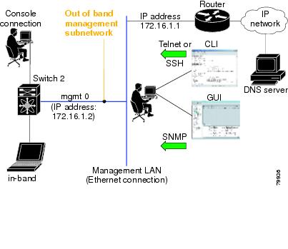
The setup scenario differs based on the subnet to which you are adding the new switch. You must configure a switch in the Cisco MDS 9000 Family with an IP address to enable management connections from outside of the switch.
Note
•
•
Figure 3-1 Management Access to Switches
Assigning Setup Information
This section describes how to initially configure the switch for both out-of-band and in-band management.
Note
Tip
Configuring Out-of-Band Management
Note
To configure the switch for first time out-of-band access, follow these steps:
Step 1
Step 2
This setup utility will guide you through the basic configuration ofthe system. Setup configures only enough connectivity for managementof the system.Press Enter incase you want to skip any dialog. Use ctrl-c at anytimeto skip away remaining dialogs.Would you like to enter the basic configuration dialog (yes/no): yesThe setup utility guides you through the basic configuration process. Type Ctrl-c at any prompt, to end the configuration process.
Step 3
Enter the password for admin: adminStep 4
Create another login account (yes/no) [n]: yesWhile configuring your initial setup, you can create an additional user account (in the network-admin role) besides the administrator's account. See the "Role-Based Authorization" section for information of default roles and permissions.
a.
Enter the user login ID: user_nameb.
Enter the password for user_name: user-passwordStep 5
Configure SNMPv3 Management parameters (yes/no) [y]: yesa.
SNMPv3 user name [admin]: adminb.
SNMPv3 user authentication password : admin_pass
Note
By default if the admin password is at least 8 characters, then the SNMP authentication password will be same as admin password (at least 8 characters). If the admin password is less than 8 characters, then you need to provide a new password for SNMP.
The admin password can have a minimum of 1 character, but the SNMP authentication password must have a minimum of 8 characters.Step 6
Configure read-only SNMP community string (yes/no) [n]: yesa.
SNMP community string: snmp_communityStep 7
Note
Enter the switch name: switch_nameStep 8
Continue with Out-of-band (mgmt0) management configuration? [yes/no]: yesa.
Mgmt0 IP address: ip_addressb.
Mgmt0 IP netmask: subnet_maskStep 9
Continue with in-band (VSAN1) management configuration? (yes/no) [no]: noStep 10
Enable the ip routing capabilities? (yes/no) [y]: yesa.
Configure static route: (yes/no) [y]: yesa.
Destination prefix: dest_prefixb.
Destination prefix mask: dest_maskc.
Next hop ip address: next_hop_address
Note
b.
Configure the default-network: (yes/no) [y]: yesa.
Note
Default network IP address: dest_prefixc.
Configure the default-gateway: (yes/no) [y]: yesa.
IP address of the default-gateway: default_gatewayStep 11
Configure the DNS IP address? (yes/no) [y]: yesa.
DNS IP address: name_serverStep 12
Configure the default domain name? (yes/no) [n]: yesa.
Default domain name: domain_nameStep 13
Enable the telnet service? (yes/no) [y]: yesStep 14
Enabled SSH service? (yes/no) [n]: yesStep 15
Type the SSH key you would like to generate (dsa/rsa/rsa1)? dsaStep 16
Enter the number of key bits? (512 to 2048): 768Step 17
Configure NTP server? (yes/no) [n]: yesa.
NTP server IP address: ntp_server_IP_addressStep 18
Configure default switchport interface state (shut/noshut) [shut]: shutStep 19
Configure default switchport trunk mode (on/off/auto) [on]: onStep 20
Configure default zone policy (permit/deny) [deny]: permitPermits traffic to flow to all members of the default zone.
Step 21
Step 22
The following configuration will be applied:username admin password admin_pass role network-adminusername user_name password user_pass role network-adminsnmp-server user admin network-admin auth md5 admin_pass priv admin_passsnmp-server community snmp_community roswitchname switchinterface mgmt0ip address ip_address subnet_maskno shutdownip routingip route dest_prefix dest_mask dest_addressip default-network dest_prefixip default-gateway default_gatewayip name-server name_serverip domain-name domain_nametelnet server enablessh key dsa 768 forcessh server enablentp server ntp_serversystem default switchport shutdownsystem default switchport trunk mode onno zone default-zone permit vsan 1-4093Would you like to edit the configuration? (yes/no): noStep 23
Use this configuration and save it? (yes/no):yes
Caution
In-Band Management Configuration
The in-band management logical interface is VSAN 1. This management interface uses the Fibre Channel infrastructure to transport IP traffic. An interface for VSAN 1 is created on every switch in the fabric. Each switch should have it's VSAN 1 interface configured with an IP address in the same subnetwork. A default route, pointing to the switch that provides access to the IP network should be configured on every switch in the Fibre Channel fabric (see "Configuring and Managing VSANs").
Note
To configure a switch for first time in-band access, follow these steps:
Step 1
Step 2
---- Basic System Configuration Dialog ----This setup utility will guide you through the basic configuration ofthe system. Setup configures only enough connectivity for managementof the system.Press Enter incase you want to skip any dialog. Use ctrl-c at anytimeto skip away remaining dialogs.Would you like to enter the basic configuration dialog (yes/no): yesThe setup utility guides you through the basic configuration process. Type Ctrl-c from any prompt, to abort the configuration process.
Step 3
Enter the password for admin: adminStep 4
Create another login account (yes/no) [no]: noStep 5
Configure SNMPv3 Management parameters (yes/no) [y]: yesa.
SNMPv3 user name [admin]: user_nameBy default, the SNMP user name is admin.
b.
SNMPv3 user authentication password [admin_pass]: admin_pass
Note
By default if the admin password is at least 8 characters, then the SNMP authentication password will be same as admin password (at least 8 characters). If the admin password is less than 8 characters, then you need to provide a new password for SNMP.
The admin password can have a minimum of 1 character, but the SNMP authentication password must have a minimum of 8 characters.Step 6
a.
Configure read-only SNMP community string (yes/no) [n]: nob.
Configure read-only SNMP community string (yes/no) [n]: yesc.
SNMP community string: snmp_communityStep 7
Note
Enter the switch name: switch_nameStep 8
Continue with Out-of-band (mgmt0) management configuration? [yes/no]: noStep 9
Continue with in-band (VSAN1) management configuration? (yes/no) [no]: yesa.
VSAN1 IP address: ip_addressb.
VSAN1 IP net mask: subnet_maskStep 10
Enable ip routing capabilities? (yes/no) [y]: yesa.
Configure static route: (yes/no) [y]: nob.
Configure the default-network: (yes/no) [y]: noc.
Configure the default-gateway: (yes/no) [y]: yesa.
IP address of the default-gateway: default_gatewayStep 11
Configure the DNS IP address? (yes/no) [y]: noStep 12
Configure the default domain name? (yes/no) [n]: noStep 13
Enable the telnet service? (yes/no) [y]: noStep 14
Enabled SSH service? (yes/no) [n]: yesStep 15
Type the SSH key you would like to generate (dsa/rsa/rsa1)? rsaStep 16
Enter the number of key bits? (512 to 1024): 1024Step 17
Configure NTP server? (yes/no) [n]: noStep 18
Configure default switchport interface state (shut/noshut) [shut]: noshutStep 19
Configure default switchport trunk mode (on/off/auto) [on]: autoStep 20
Configure default zone policy (permit/deny) [deny]: denyStep 21
Step 22
The following configuration will be applied:username admin password admin_pass role network-adminsnmp-server user snmp_user network-admin auth md5 snmp_pass priv snmp_passsnmp-server community snmp_community rwswitchname switchinterface vsan1ip address ip_address subnet_maskno shutdownip default-gateway default_gatewayno telnet server enablessh key rsa 1024 forcessh server enableno system default switchport shutdownsystem default switchport trunk mode autono zone default-zone deny vsan 1-4093Would you like to edit the configuration? (yes/no): noStep 23
Use this configuration and save it? (yes/no):yes
Caution
Using the setup Command
If you wish to make changes to the initial configuration at a later time, you can issue the setup command in EXEC mode.
switch# setup---- Basic System Configuration Dialog ----This setup utility will guide you through the basic configuration ofthe system. Setup configures only enough connectivity for managementof the system.*Note: setup always assumes a predefined defaults irrespectiveof the current system configuration when invoked from CLI.Press Enter incase you want to skip any dialog. Use ctrl-c at anytimeto skip away remaining dialogs.Would you like to enter the basic configuration dialog (yes/no): yesThe setup utility guides you through the basic configuration process.
Assigning a Switch Name
Each switch in the fabric requires a unique name. You can assign names to easily identify the switch by its physical location, its SAN association, or the organization to which it is deployed. The assigned name is displayed in the command-line prompt.
Note
This guide refers to a switch in the Cisco MDS 9000 Family as switch, and uses the switch# prompt.
To change the name of the switch, follow these steps:
Assigning SNMP Switch Contact Information
Use the snmp-server command to set the contact information, switch location, and switch name. They are each limited to 32 characters (without spaces). Use the no form of the command to remove the system contact information. For more information on other snmp-server commands see the "SNMP Security" section
To configure contact information, follow these steps:
Accessing the Switch
After initial configuration, you can access the switch in one of three ways (see Figure 3-2):
•
•
Note
•
Figure 3-2 Switch Access Options
Where Do You Go Next?
After reviewing the default configuration, you can change it or perform other configuration or management tasks. The initial setup can only be performed at the CLI. However, you can continue to configure other software features, or access the switch after initial configuration by using either the CLI or the Element Manager and Fabric Manager GUIs.
To use the Cisco MDS 9000 Fabric Manager, refer to the Cisco MDS 9000 Family Fabric Manager User Guide.
Verifying the Module Status
Before you begin configuring the switch, you need to ensure that the modules in the chassis are functioning as designed. To verify the status of a module at any time, issue the show module command in EXEC mode. A sample output of the show module command follows:
switch# show moduleMod Ports Module-Type Model Status--- ----- ------------------------------- ------------------ ------------3 16 1/2 Gbps FC Module DS-X9016 ok5 0 Supervisor/Fabric-1 DS-X9530-SF1-K9 active *9 16 1/2 Gbps FC Module DS-X9016 okMod Sw Hw World-Wide-Name(s) (WWN)--- ----------- ------ --------------------------------------------------3 1.0(1.22) 0.0 20:81:00:05:30:00:12:5e to 20:90:00:05:30:00:12:5e5 1.0(1.22) 0.0 --9 1.0(1.22) 0.0 22:01:00:05:30:00:12:5e to 22:10:00:05:30:00:12:5eMod MAC-Address(es) Serial-Num--- -------------------------------------- ----------3 00-05-30-00-76-26 to 00-05-30-00-76-2a5 00-05-30-00-53-ae to 00-05-30-00-53-b29 00-05-30-00-64-b6 to 00-05-30-00-64-ba* this terminal sessionIf the status is OK or active, you can continue with your configuration (see "Managing Modules").
Configuring Time
Switches in the Cisco MDS 9000 Family use Coordinated Universal Time (UTC), which is the same as Greenwich Mean Time (GMT). To change the default time on the switch, issue the clock command from EXEC mode.
switch# clock set <HH:MM:SS> <DD> <Month in words> <YYYY>For example:
switch# clock set 12:07:50 23 September 2002Mon Sep 23 12:07:50 UTC 2002HH represents hours in military format (15 for 3 p.m.), MM is minutes (58), SS is seconds (09), DD is the date (02), Month is the month in words (August), and YYYY is the year (2002).
Note
Configuring the Time Zone
You can specify a time zone for the switch to display the time.
To specify the local time without the daylight savings feature, follow these steps:
Setting the Daylight Saving Time Adjustment
Following U.S. standards, you can have the switch advance the clock one hour at 2:00 a.m. on the first Sunday in April and move back the clock one hour at 2:00 a.m. on the last Sunday in October. You can also explicitly specify the start and end dates and times and whether or not the time adjustment recurs every year.
To enable the daylight saving time clock adjustment according to the U.S. rules, follow these steps:
NTP Configuration
A Network Time Protocol (NTP) server provides a precise time source (radio clock or atomic clock) to synchronize the system clocks of network devices. NTP is transported over User Datagram Protocol UDP/IP. All NTP communications use UTC. An NTP server receives its time from a reference time source, such as a radio clock or atomic clock, attached to the time. NTP distributes this time across the network.
In a large enterprise network, having one time standard for all network devices is critical for management reporting and event logging functions when trying to correlate interacting events logged across multiple devices. Many enterprise customers with extremely mission-critical networks maintain their own stratum-1 NTP source.
Time synchronization happens when several frames are exchanged between clients and servers. The switches in client mode know the address of one or more NTP servers. The servers act as the time source and receive client synchronization requests.
By configuring an IP address as a peer, the switch will obtain and provide time as required. The peer is capable of providing time on its own and is capable of having a server configured. If both these instances point to different time servers, your NTP service will be more reliable. Thus, even if the active server link is lost, you can still maintain the right time due to the presence of the peer.
Tip
If you only configure a peer, the most accurate peer takes on the role of the NTP server and the other peer(s) act as a peer(s). Both machines end at the right time if they have the right time source or if they point to the right NTP source.
To configure NTP in a server association, follow these steps:
NTP Configuration Guidelines
The following guidelines apply to all NTP configurations:
•
•
•
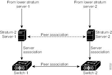
If the network is configured robustly, even a server down time will not affect well-configured switches in the network. Figure 3-3 displays a network with two NTP stratum 2 servers and two switches.
Figure 3-3 NTP Peer and Server Association
In this configuration, the switches were configured as explained below:
•
–
–
–
•
–
•
–
–
•
–
–
–
–
Configuring the Management Port
The management port on the switch allows multiple simultaneous Telnet or SNMP sessions.
You can remotely configure the switch through the management port, but first you must configure some IP parameters (IP address, subnet mask) so that the switch is reachable. You can manually configure the management port interface from the CLI.
Note
To obtain remote management access using Telnet (CLI) or SNMP (GUI), follow these steps:
In some cases, a switch interface might be administratively shut down. You can check the status of an interface at any time by using the show interface command.
The management port (mgmt0) is autosensing and operates as full duplex mode and 100 Mbps speed. The speed and mode cannot be configured.
Note
Configuring Default Gateways
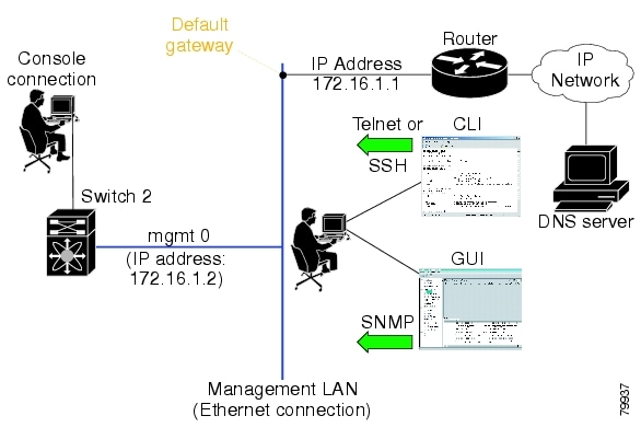
The supervisor module sends IP packets with unresolved destination IP addresses to the default gateway (see Figure 3-4).
Figure 3-4 Default Gateway
To configure the IP address of the default gateway, follow these steps:
Step 1
Enters configuration mode.
Step 2
Configures the 172.16.1.1 IP address.
Disabling a Telnet Server
The Telnet server is enabled by default on all switches in the Cisco MDS 9000 Family. If you require a secure SSH connection, you need to disable the default Telnet connection and then enable the SSH connection (see the "Enabling SSH Service" section).
Note
Make sure the terminal is connected to the switch and that the switch and terminal are on. To allow Telnet connections to the switch, follow these steps:
About Flash Devices
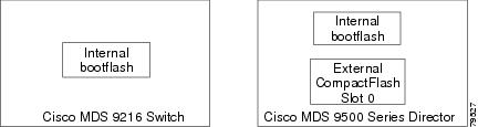
Every switch in the Cisco MDS 9000 Family contains one internal bootflash: that resides in the supervisor or switching module. Cisco MDS 9500 Series directors contain an additional external CompactFlash called slot0: (see Figure 3-5 and Figure 3-6).
Figure 3-5 Flash Devices in the Cisco MDS 9000 Supervisor Module
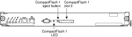
Figure 3-6 External CompactFlash in the Cisco MDS 9000 Supervisor Module
The external CompactFlash, an optional device for MDS 9500 series Directors, can be used for storing software images, logs and core dumps.
Formatting Flash Disks and File Systems
By formatting a flash disk or a file system, you are essentially clearing out the contents of the disk or the file system and restoring it to its factory-shipped state.
Initializing bootflash:
When a switch is shipped, the init system command is already performed and you do not need to issue it again. Initializing the switch resets the entire internal disk and erases all data in the bootflash: partition. The internal disk is composed of several file systems with bootflash: being one of them. All files in bootflash: are erased and you must download the system and kickstart images again. If you issue an init system command at any time, you don't have to format the bootflash: again since bootflash: is automatically formatted.
Note
If bootflash: is found corrupted during a boot sequence, you will see the following message:
ERROR:bootflash: has unrecoverable error; please do "format bootflash:"Use the format bootflash: command to only format the bootflash: filesystem. You can access the format bootflash: command from either the switch# or the switch(boot)# prompts.
If you issue the format bootflash: command, you need to download the kickstart and system images again.
Formatting Slot0:
Be sure to format an external CompactFlash device before using it to save files or images.
You can verify if the external CompactFlash device is formatted by inserting it into slot0: and issuing the dir slot0: command.
•
•
Device unavailableIn this case, you need to format the CompactFlash device using the format slot0: command.
Note
Working with Configuration Files
This section describes how to work with configuration files and has the following topics:
•
•
Guidelines for Creating and Using Configuration Files
Configuration files can contain some or all of the commands needed to configure one or more switches. For example, you might want to download the same configuration file to several switches that have the same hardware configuration so that they have identical module and port configurations.
Certain commands must be followed by a blank line in the configuration file. Without these blank lines, the commands might disconnect your Telnet session. Before disconnecting a session, the switch prompts you for confirmation. The blank line acts as a carriage return, which indicates a negative response to the prompt retaining the Telnet session.
Include a blank line after the following command in a configuration file:
interface mgmt0 disableViewing Configuration Files
To view the running configuration file, use the show running-config command:
switch# show running-configBuilding Configuration ...interface port-channel 98interface fc1/1interface fc1/2interface mgmt0ip address 172.22.95.112 255.255.255.0no shutdownvsan databasevsan 2clock summer-time Pacific 1 Sun Apr 02:00 5 Sun Oct 02:00 60switchname switch112To view the startup configuration file, use the show startup-config command:
switch# show startup-configinterface port-channel 98interface fc1/1channel-group 98 forceno shutdowninterface mgmt0ip address 172.22.95.112 255.255.255.0boot system system-237; ep-41boot kickstart boot-237 ep-41ip domain-name cisco.comDownloading Configuration Files to the Switch
You can configure a switch in the Cisco MDS 9000 Family by using configuration files you create or download from another switch. In addition, you can store configuration files on a bootflash device on the supervisor module and you can configure the switch using a configuration stored on an external CompactFlash disk.
Before you begin downloading a configuration file using a remote server, do the following:
•
•
•
Note
From a Remote Server
To configure a switch in the Cisco MDS 9000 Family using a configuration file downloaded from a remote server using TFTP, FTP, SCP, or SFTP, follow these steps:
Step 1
Step 2
copy <scheme> :// <server address> system: running-config command.The scheme is TFTP, FTP, SCP, or SFTP.
Step 3
The configuration file downloads and the commands are executed as the file is parsed line by line.
Use the following command to download a configuration file from a remote server to the running configuration.
switch# copy <scheme>://<url> system:running-configUse the following command to download a configuration file from a remote server to the startup configuration.
switch# copy <scheme>://<url> nvram:startup-configFrom an External Flash (slot0:)
Note
To configure a switch in the Cisco MDS 9000 Family using a configuration file stored on an external CompactFlash disk, follow these steps:
Step 1
Step 2
Step 3
The commands are executed as the file is parsed line by line.
Use the following command to download a configuration file from an external CompactFlash to the running configuration.
switch copy slot0:dns-config.cfg system:running-configUse the following command to download a configuration file from an external CompactFlash to the startup configuration.
switch copy slot0:dns-config.cfg nvram:startup-configTo a Remote Server
To save a configuration file to a remote server like TFTP, FTP, SCP, or SFTP, follow these steps:
Step 1
Step 2
Scheme can be TFTP, FTP, SCP, or SFTP.
Step 3
The configuration file is saved to the remote server.
Use the following command to save a running configuration file to a remote server:
switch# copy system:running-config <scheme>://<url>Use the following command to save a startup configuration file to a remote server
switch# copy nvram:startup-config <scheme>://<url>To an External CompactFlash Disk
To save a configuration file on an external CompactFlash disk, follow these steps:
Step 1
Step 2
Step 3
The configuration file is saved to the CompactFlash disk.
Use the following command to save a running configuration file to an external CompactFlash disk.
switch# copy system:running-config slot0:dns-config.cfgUse the following command to save a startup configuration file to an external CompactFlash disk.
switch# copy system:startup-config slot0:dns-config.cfgSaving the Configuration
After you have created a configuration, you save the configuration using the following copy command:
switch# copy system:running-config nvram:startup-configThe copy running-config startup-config command is an alias to the previous command and is used frequently throughout this guide.
Copying Files
The syntax for the copy command follows and is explained in Table 3-1.
switch# copy <scheme>://<username@><server>/<file name>
<scheme>://<username@><server>/<file name>
Table 3-1 copy Command Syntax
bootflash
active-sup
standby-supUser-specified
slot0
—
User-specified
volatile
—
User-specified
nvram
—
startup-config or snapshot-config
system
—
running-config
tftp1
IP address or DNS name
User-specified
ftp
scp (secure copy)
sftp
core
—
Process identifier number
1 When downloading and uploading files, a TFTP limitation restricts a TFTP client to a 32 MB file size and some TFTP servers to a 16 MB file size.
•
switch# copy bootflash:system_imgage bootflash://sup-2/system_image
Note
•
switch# copy nvram:snapshot-config nvram:startup-config
Warning: this command is going to overwrite your current startup-config.
Do you wish to continue? {y/n} [y] y
•
switch# copy system:running-config bootflash:my-config•
switch# copy tftp://172.16.10.100/system-237.img bootflash:system-237.img•
switch# copy sftp://172.16.10.100/myscript.txt volatile:myscript.txt
Note
Backing up the Current Configuration
Before installing or migrating to any software configuration, back up the startup configuration.
•
switch# copy nvram:startup-config nvram:snapshot-config•
switch# copy nvram:startup-config bootflash:my-config•
switch# copy nvram:startup-config copy tftp://172.16.10.100/my-config•
switch# copy system:running-config bootflash:my-configRolling Back to a Previous Configuration
All switch configurations reside in the internal bootflash: file system. If your internal bootflash: file system is corrupted, you could potentially lose your configuration. Save and back up your configuration file periodically.
•
switch# copy nvram:snapshot-config nvram:startup-config
Note
•
switch# copy bootflash:my-config nvram:startup-config•
switch# copy tftp://172.16.10.100/my-config nvram:startup-config
Note
Deleting Files
To delete files on a Flash device, follow these steps:
Step 1
Deletes files from a directory
Step 2
Verifies the files are deleted.
•
switch# delete dns_config.cfg•
switch# delete slot0:dns_config.cfg•
switch# delete slot0:test
Delete slot0:test? [confirm]
•
switch# delete bootflash:my-dirConfiguring Line Console Settings
Console ports on Cisco switches are set up for quick and easy access through any standard RS-232 data terminal equipment (DTE) device.
You can perform the configuration specified in this section only if you are connected to the serial console.
Note
Console Port Speed
The default console baud rate is 9600 baud. The valid range is between 110 and 115,200 bps—110, 150, 300, 600, 1200, 2400, 4800, 9600, 19200, 28800, 38400, 57600, 115200. Be sure to specify one of these exact values.
For the purposes of this document, the default console port speed of 9600 baud is assumed.
Caution
To configure console port speed, follow these steps:
If you specify an invalid speed, you will receive the following error message:
switch(config-console)# speed 111Error: 111 is not supported speedSupported speed are 110, 150, 300,2400, 4800, 9600, 19200, 28800, 38400, 57600 (56K), and 115200Device Control Parameters
Be sure to set the values for the device control parameters when setting up the terminal:
•
•
•
You can change these parameters to meet the requirements of the terminal or host to which you are attached.
To configure device control parameters, follow these steps: