Feedback
Table Of Contents
Installing the Cisco MDS 9216 Switch
Unpacking and Inspecting the Switch
Installing the Chassis in a Cabinet or Rack
Installing the Switch in a Cabinet with Insufficient Front Clearance
Installing Front rack-mount Brackets for Cabinets with 26 Inches or Greater of Rail Spacings
Installing Front rack-mount Brackets for Cabinets with Less Than 26 Inches of Rail Spacings
Installing the Cisco MDS 9216 Switch Rear-Facing into Cabinet
Removing and Installing Components
Removing and Installing Switching and Services Modules
Removing a Caching Services Module
Removing Other Switching or Services Modules
Installing a Switching or Services Module, Including Caching Services Modules
Verifying Installation of a Switching or Services Module
Maintaining a Caching Services Module
Maintaining the Batteries on the Caching Services Module
Maintaining the Disk Drives on the Caching Services Module
Removing and Installing Power Supplies
Removing and Installing the Fan Module
Removing the Cisco MDS 9216 Switch
Installing the Cisco MDS 9216 Switch
This chapter describes how to install the Cisco MDS 9216 Switch and its components, and it includes the following information:
•
Installing the Chassis in a Cabinet or Rack
•
•
Note
Warning
This warning symbol means danger. You are in a situation that could cause bodily injury. Before you work on any equipment, be aware of the hazards involved with electrical circuitry and be familiar with standard practices for preventing accidents. Use the statement number provided at the end of each warning to locate its translation in the translated safety warnings that accompanied this device. Statement 1071
SAVE THESE INSTRUCTIONS
Warning
Warning
Warning
Note
Pre-Installation
This section includes the following information:
•
Installation Options
The Cisco MDS 9216 Switch can be installed using the following methods:
•
–
–
•
–
–
•
–
For instructions on installing the switch using the rack-mount kit shipped with the switch, see the "Installing the Chassis in a Cabinet or Rack" section.
For instructions on installing the switch using the optional, separately purchased Telco and EIA Shelf Bracket Kit, see the "Cisco MDS 9000 Family Telco and EIA Shelf Bracket" section.
Note
Installation Guidelines
Follow these guidelines when installing the Cisco MDS 9216 Switch:
•
•
•
•
•
Note
•
•
Caution
•
If you are using a 200- or 240-VAC power source in North America, the circuit must be protected by a two-pole circuit breaker.
Caution
•
–
–
–
–
–
Required Equipment
Gather the following items before beginning the installation:
•
•
•
•
•
The following additional items (not found in the accessory kit) are required to ground the chassis:
•
•
•
Unpacking and Inspecting the Switch
Caution
Tip
Note
Note
To inspect the shipment, follow these steps:
Step 1
•
•
•
•
•
•
Step 2
•
•
•
•
Installing the Chassis in a Cabinet or Rack
This section describes how to use the rack-mount kit provided with the switch to install the Cisco MDS 9216 Switch into a cabinet or rack that meets the requirements described in "Cabinet and Rack Installation." All Cisco MDS 9216 Switch switches use the same installation procedure.
Caution
The rack-mount kit provided with the switch contains the items listed in Table 2-1. If you do not find all the parts listed in Table 2-1, you may have an older version of the rack-mount kit, which only included the front rack-mount brackets. If this is the case, you can either install the switch in the rack with just the front rack-mount brackets, or contact your customer service representative for a current version of the rack-mount kit.
Note
To install the switch in a cabinet or rack using the rack-mount kit provided with the switch, follow these steps:
Step 1
a.
b.
Figure 2-1 Attaching Front Rack-Mount Bracket to the Cisco MDS 9216 Switch
Step 2
a.
Note
b.
Figure 2-2 Installing C Brackets onto the Cisco MDS 9216 Switch
Figure 2-3 C Brackets for the Cisco MDS 9216 Switch (Close-Up View)
Step 3
If you are installing the optional cable guides, place the cable guides in front of the front rack-mount brackets, and then pass the screws through the cable guides, front rack-mount brackets, and mounting rail. You can install one or both cable guides; if installing a single cable guide, it can be installed on either side.
Figure 2-4 Installing the Cisco MDS 9216 Switch in the Rack
Step 4
Step 5
Figure 2-5 Inserting and Installing Slider Rails (Back View)
Figure 2-6 shows the Cisco MDS 9216 Switch completely installed in a rack.
Figure 2-6 Cisco MDS 9216 Switch Chassis Installed in the Rack
Installing the Switch in a Cabinet with Insufficient Front Clearance
This section describes how to use the rack-mount kit provided with the switch to install the Cisco MDS 9216 Switch into a cabinet with insufficient front-facing clearance. The Cisco MDS 9216 Switch is installed rear-facing to provide adequate clearance for the fiber optic cables. This cabinet meets the requirements described in "Cabinet and Rack Installation," except the cabinet has less than three inches of clearance between the inside of the front door or bezel panel and the front cabinet mounting rails. This rear-facing installation is necessary to ensure that the minimum bend radius for the fiber optic cables is maintained. In these cabinets, the Cisco MDS 9216 Switch is mounted backwards, with the fiber optic cables facing toward the rear of the cabinet and the power supplies facing the front of the cabinet.
Caution
The rack-mount kit provided with the switch contains the items listed in Table 2-1. If you do not find all of the parts listed in Table 2-1, you may have an older version of the rack-mount kit, which only included the front rack-mount brackets. If this is the case, you can either install the switch in the rack with just the front rack-mount brackets, or contact your customer service representative for a current version of the rack-mount kit.
Note
Installing Front rack-mount Brackets for Cabinets with 26 Inches or Greater of Rail Spacings
The front rack-mount brackets for the Cisco MDS 9216 Switch must be installed onto the switch prior to installing the switch into the cabinet. Follow these steps for cabinets with front-mounting rail to rear-mounting rail spacings greater or equal to 26 inches.
Step 1
a.
b.
Figure 2-7 Attaching Front Rack-Mount Bracket to the Cisco MDS 9216 Switch
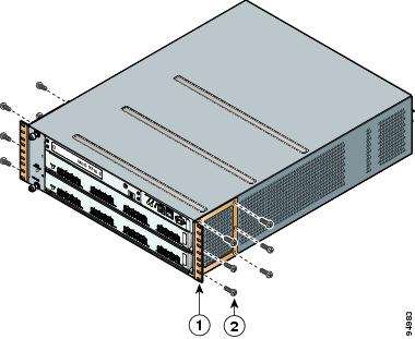
Step 2
a.
Figure 2-8 Installing C Brackets onto the Cisco MDS 9216 Switch
Figure 2-9 C Brackets for the Cisco MDS 9216 Switch (Close-Up View)
Note
b.
Installing Front rack-mount Brackets for Cabinets with Less Than 26 Inches of Rail Spacings
The front rack-mount brackets for the Cisco MDS 9216 Switch switch must be installed onto the switch prior to installing the switch into the cabinet. For cabinets with less than 26 inches of rail-to-rail spacing, the front rack-mount bracket must be installed 180 degrees from normal. Follow these steps for cabinets with front-mounting rail to rear-mounting rail spacings less than 26 inches that need to be mounted backwards to maintain adequate fiber optic clearances.
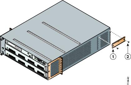
Step 1
a.
Figure 2-10 Front rack-mount Brackets (Rotated) Installed on the Cisco MDS 9216 Switch
b.
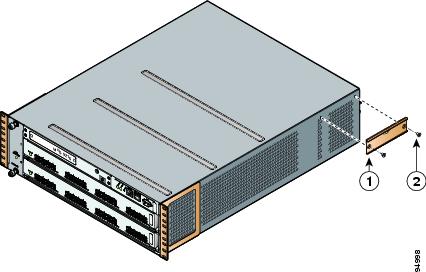
Step 2
a.
Figure 2-11 Installing C Brackets onto the Cisco MDS 9216 Switch
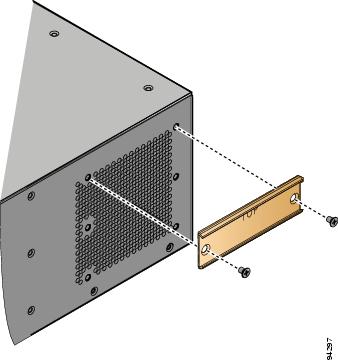
Figure 2-12 C Brackets for the Cisco MDS 9216 Switch (Close-Up View)
Note
b.
Installing the Cisco MDS 9216 Switch Rear-Facing into Cabinet
To install the switch rear-facing in a cabinet using the rack-mount kit provided with the switch, for cabinets with insufficient front-facing clearance, follow these steps:
Step 1
If you are installing the optional cable guides, place the cable guides in front of the front rack-mount brackets, and then pass the screws through the cable guides, front rack-mount brackets, and mounting rail. You can install one or both cable guides; if installing a single cable guide, it can be installed on either side.
Note
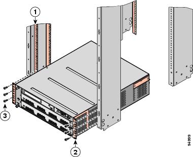
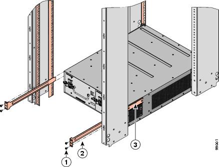
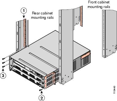
Figure 2-13 Installing the Cisco MDS 9216 Switch (Rear-Facing) in the Rack
Step 2
Step 3
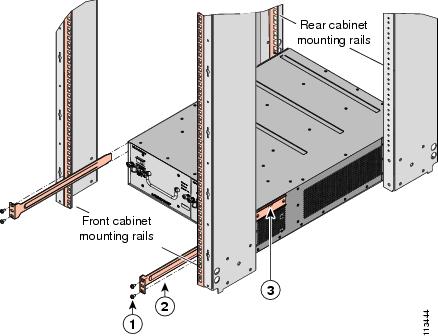
Figure 2-14 Inserting and Installing Slider Rails (Front View)
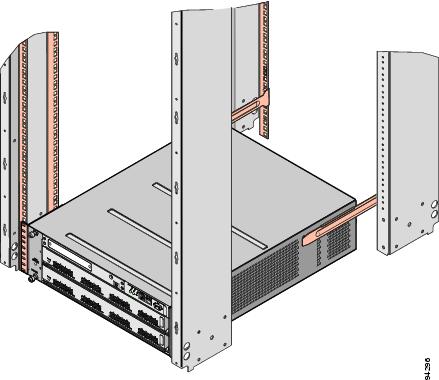
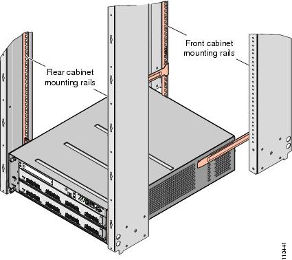
Figure 2-15 shows the Cisco MDS 9216 Switch completely installed in a rack.
Note
Figure 2-15 Cisco MDS 9216 Switch Installed in the Rack (Back View)
Grounding the Chassis
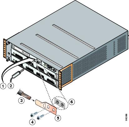
The chassis has a grounding pad with two threaded M4 holes for attaching a grounding lug. Figure 2-16 shows the system ground location on the Cisco MDS 9216 Switch.
Warning
Caution
Caution
Figure 2-16 Location of System Ground on the Cisco MDS 9216 Switch
ESD socket (on switch)
Screws, M4, with square cone washers
ESD plug
Grounding lug
Grounding cable
Close-up of grounding pad on switch
To attach the grounding lug and cable to the chassis, follow these steps:
Step 1
Step 2
Step 3
Step 4
Step 5
Step 6
Step 7
Starting Up the Switch
This section provides instructions for powering up the switch and verifying component installation.
Warning
Warning
Caution
Note
To power up the switch and verify hardware operation, follow these steps:
Step 1
Step 2
Step 3
Note
Step 4
Step 5
Step 6
Step 7
Caution
Step 8
•
•
–
–
–
•
–
–
•
Note
If any LEDs are orange (except on the CSM) or red after the initial boot processes are complete, see "Troubleshooting."
Step 9
Note
Step 10
Step 11
Note
Removing and Installing Components
This section provides the following information:
•
•
•
•
Warning
Caution
Removing and Installing Switching and Services Modules
Slot 1 is reserved for the supervisor module with its integrated multiport switching or IP services module. Slot 2 can contain an optional module. See Figure 1-1 for slot locations.
Warning
Warning
Warning
Caution
Note
This section includes the following information:
•
•
•
•
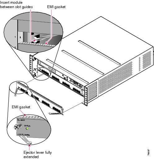
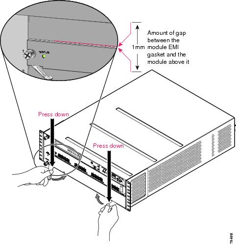
Figure 2-17 and Figure 2-18 show the positioning of a module in the chassis.
Figure 2-17 Positioning the Module in the Chassis
Figure 2-18 Clearing the EMI Gasket
Removing a Caching Services Module
Note
Warning
Warning
Caution
To remove a CSM module from the chassis, follow these steps:
Step 1
Step 2
Step 3
Step 4
a.
b.
Step 5
Step 6
Warning
Removing Other Switching or Services Modules
To remove a switching or services module from the chassis, follow these steps:
Step 1
Step 2
Step 3
a.
b.
Step 4
Step 5
Warning
Installing a Switching or Services Module, Including Caching Services Modules
The following warning applies only to the Caching Services Module:
Warning
Note
To install a module in slot 2 of the chassis, follow these steps:
Step 1
Step 2
Step 3
Step 4
a.
b.
c.
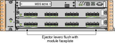
Figure 2-19 Closing the Ejector Levers
Caution
d.
Note
e.
Verifying Installation of a Switching or Services Module
To verify the module installation in slot 2, follow these steps:
Step 1
Step 2
Step 3
Step 4
Note
Maintaining a Caching Services Module
Caution
Note
This section provides the following information:
•
•
Maintaining the Batteries on the Caching Services Module
The CSM batteries last approximately three years. The following message displays in the system log when a battery fails:
Dec 5 17:14:36 sw-90.21 %SVC_BATTERY-SLOT8-4-BATTERY_CAPACITY_LOW:
Battery capacity is below the required threshold.A message also appears in the output of the show interface command.
If you see this message, contact your support provider for assistance. If a battery fails, the CSM must be replaced.
Caution
Warning
Warning
The batteries are automatically charged on a periodic basis with an SMBus compliant Level III smart charger located on the CSM. The smart charger measures the charge and recharges the battery to full if it is less than 90% of capacity.
The batteries are also automatically reconditioned on a periodic basis, one battery at a time. During reconditioning all power is drained from the battery and the battery is completely recharged, requiring approximately six hours. The Battery Status LED flashes green during the reconditioning.
Maintaining the Disk Drives on the Caching Services Module
A message displays in the system log when a disk drive requires replacement. If you see this message, contact your support provider for assistance.
If a disk drive fails, the CSM must be replaced. The other CSM(s) in the fabric contain the same data, and they can continue to provide caching services during the replacement period.
Removing and Installing Power Supplies
The Cisco MDS 9216 Switch supports dual 845-W AC power supplies that monitor output voltage and provide status to the supervisor module.
This section provides the following information:
A flat-blade or Phillips screwdriver is required to perform these procedures.
Warning
Warning
Note
Removing a Power Supply
To remove a power supply, follow these steps:
Step 1
Step 2
Step 3
Step 4
Step 5
Installing a Power Supply
To install a power supply, follow these steps:
Step 1
Step 2
Step 3
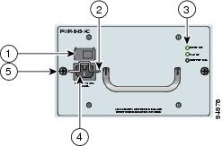
Figure 2-20 845-W AC Power Supply Front Panel
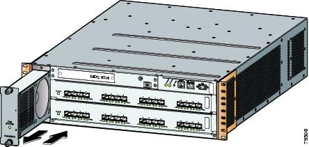
Step 4
Figure 2-21 Handling an 845-W AC Power Supply
Step 5
Step 6
Note
Step 7
Caution
Step 8
Step 9
•
•
•
If the LEDs indicate a power problem, see the "Troubleshooting the Power Supplies" section.
Removing and Installing the Fan Module
The fan module is designed to be removed and replaced while the system is operating without presenting an electrical hazard or damage to the system, provided the replacement is performed promptly.
This section provides the following information:
You will need a flat-blade or number 2 Phillips screwdriver to perform these procedures.
Caution
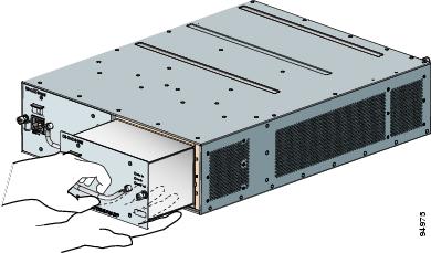
Figure 2-22 shows a fan module partially installed in the Cisco MDS 9216 Switch.
Figure 2-22 Fan Module
Removing a Fan Module
Warning
To remove a fan module, follow these steps:
Step 1
Step 2
Step 3
Caution
Installing a Fan Module
To install a fan module, follow these steps:
Step 1
Step 2
Step 3
Step 4
Note
Removing the Cisco MDS 9216 Switch
When removing the Cisco MDS 9216 Switch from the rack, remove the slider brackets first, and then the front screws fastening the front rack-mount brackets to the rack.
Note
To remove the Cisco MDS 9216 Switch from the rack, follow these steps:
Step 1
Step 2
Step 3
Step 4