Feedback
Table Of Contents
Connecting the Console Port to a Computer Using the DB-25 Adapter
Connecting the Console Port to a Computer Using the DB-9 Adapter
Supported Power Cords and Plugs
Cable and Port Specifications
This appendix includes the cables and connectors used with the Cisco MDS 9100 Series Fixed Configuration Fabric Switch, and it includes the following sections:
•
Supported Power Cords and Plugs
Caution
Cables and Adapters
The Cisco MDS 9100 Series accessory kit includes the following:
•
•
•
•
Note
Note
Console Port
The console port is an asynchronous RS-232 serial port with an RJ-45 connector. You can use the RJ-45 to RJ-45 rollover cable and the RJ-45 to DB-9 female adapter or the RJ-45 to DB-25 female DTE adapter (depending on your computer serial port) to connect the console port to a computer running terminal emulation software.
Console Port Pinouts
Table C-1 lists the pinouts for the console port on the Cisco MDS 9100 Series.
Table C-1 Console Port Pinouts
11
RTS
2
DTR
3
TxD
4
GND
5
GND
6
RxD
7
DSR
8
CTS
1 Pin 1 is connected internally to pin 8.
Connecting the Console Port to a Computer Using the DB-25 Adapter
You can use the RJ-45 to RJ-45 rollover cable and RJ-45 to DB-25 female DTE adapter (labeled "Terminal") to connect the console port to a computer running terminal emulation software. Table C-2 lists the pinouts for the console port, the RJ-45 to RJ-45 rollover cable, and the RJ-45 to DB-25 female DTE adapter.
Connecting the Console Port to a Computer Using the DB-9 Adapter
You can use the RJ-45 to RJ-45 rollover cable and RJ-45 to DB-9 female DTE adapter (labeled "Terminal") to connect the console port to a computer running terminal emulation software. Table C-3 lists the pinouts for the console port, the RJ-45 to RJ-45 rollover cable, and the RJ-45 to DB-9 female DTE adapter.
MGMT 10/100 Ethernet Port
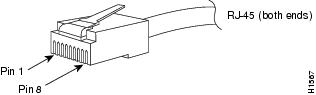
Use a modular, RJ-45, straight-through UTP cable to connect the 10/100 management Ethernet port to external hubs and switches. To connect to a router, use a crossover cable. (See Figure C-1.)
Figure C-1 RJ-45 Interface Cable Connector
Table C-4 lists the connector pinouts and signal names for a 10/100BASE-T management port (MDI) cable.
Table C-4 10/100BASE-T Management Port Cable Pinout
1
TD+
2
TD-
3
RD+
6
RD-
4
Not used
5
Not used
7
Not used
8
Not used
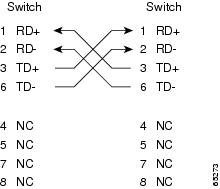
Figure C-2 shows a schematic of the 10/100BASE-T cable.
Figure C-2 Twisted-Pair 10/100BASE-T Cable Schematic
Supported Power Cords and Plugs
A separate power cord is provided for each power supply. Standard power cords or jumper power cords are available for connection to a power distribution unit having IEC 60320 C13 outlet receptacles. The jumper power cords, for use in cabinets, are available as an option instead of the standard power cords.
Power Cords
The standard power cords have an IEC C15 connector on the end that plugs into the switch. The optional jumper power cords have an IEC C15 connector on the end that plugs into the switch, and an IEC C14 connector on the end that plugs into an IEC C13 outlet receptacle.
Note
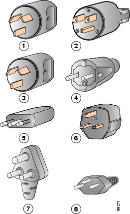
Figure C-3 shows the supported plugs for the Cisco MDS 9100 Series power supplies.
Figure C-3 300-W Power Supply Plugs
Jumper Power Cord
Figure C-4 shows the C14 and C15 connectors on the optional jumper power cord for the Cisco MDS 9100 Series switch. The C15 connector connects into the C14 inlet on the Cisco MDS 9100 Series power supply, while the C14 connector connects into the C13 receptacle of a power distribution unit for a cabinet.
Figure C-4 Connectors on Jumper Power Cord for Cisco MDS 9100 Series