Feedback
Table Of Contents
Installing a Circuit Board in a PIX 515
Installing a Circuit Board in a PIX 520 and Earlier Model
Installing a Circuit Board
Before using this chapter, refer to "" for instructions on how to open the case for each model of PIX Firewall. You can use the information in this chapter to install an interface card, such as for Ethernet, Token Ring, or FDDI, or a Private Link VPN card.
This chapter describes the following topics:
•
Installing a Circuit Board in a PIX 515
•
Installing a Circuit Board in a PIX 515
Note
To install a circuit board in a PIX 515:
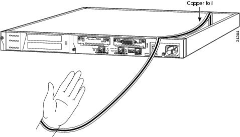
Step 1
Figure 7-1 Attaching the PIX 515 Grounding Strap
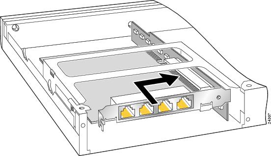
Step 2
Step 3
Figure 7-2 Inserting a Board into a PIX 515
Note
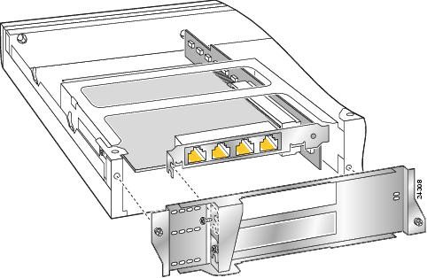
Step 4
Figure 7-3 Attaching PIX 515 Back Cover Plate
Step 5
Step 6
Installing a Circuit Board in a PIX 520 and Earlier Model
To install a circuit board in a PIX 520 and earlier model:
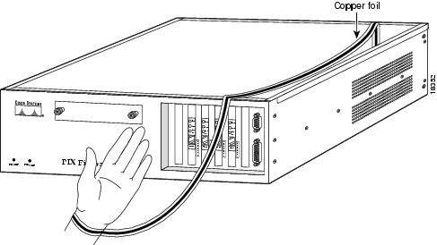
Step 1
Figure 7-4 Attaching Wrist Strap to Hand and to the PIX Firewall
Step 2
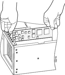
Figure 7-5 Installing the New Board
Step 3
Note
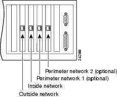
Figure 7-6 PIX Firewall Network Interfaces
Step 4
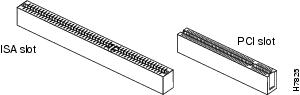
Figure 7-7
Identify the ISA and PCI Slots
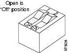
Figure 7-8
Note That Dip Switch is Off When in "Open" Position
Step 5
Step 6
Step 7