-
Cisco NAC Appliance - Clean Access Manager Configuration Guide, Release 4.9(2)
-
About This Guide
-
Introduction
-
Device Management: Adding Clean Access Servers, Adding Filters
-
Switch Management: Configuring Out-of-Band Deployment
-
Wireless LAN Controller Management: Configuring Wireless Out-of-Band Deployment
-
Configuring User Login Page and Guest Access
-
User Management: Configuring User Roles and Local Users
-
User Management: Configuring Authentication Servers
-
User Management: Traffic Control, Bandwidth, Schedule
-
Configuring Cisco NAC Appliance for Agent Login and Client Posture Assessment
-
Cisco NAC Appliance Agents
-
Monitoring and Troubleshooting Agent Sessions
-
Configuring Network Scanning
-
Monitoring Event Logs
-
Administering the CAM
-
Error and Event Log Messages
-
API Support
-
MIB Support
-
Open Source License Acknowledgements
-
 Feedback
Table Of Contents
User Management: Traffic Control, Bandwidth, Schedule
View Global Traffic Control Policies
Add Global IP-Based Traffic Policies
Add Global Host-Based Traffic Policies
Add Trusted DNS Server for a Role
View IP Addresses Used by DNS Hosts
Proxy Servers and Host Policies
Add Global Layer 2 Ethernet Traffic Policies
Configure User Session and Heartbeat Timeouts
OOB (L2) and Multihop (L3) Sessions
Session Timer / Heartbeat Timer Interaction
Configure Session Timer (per User Role)
Configure Heartbeat Timer (User Inactivity Timeout)
Configure OOB Heartbeat Timer (per User Role)
Configure Policies for Agent Temporary and Quarantine Roles
Configure Agent Temporary Role
Configure Session Timeout for the Temporary Role
Configure Traffic Control Policies for the Temporary Role
Configure Network Scanning Quarantine Role
Create Additional Quarantine Role
Configure Session Timeout for Quarantine Role
Configure Traffic Control Policies for the Quarantine Role
Allowing Authentication Server Traffic for Windows Domain Authentication
Allowing Traffic for Enterprise AV Updates with Local Servers
Adding Traffic Policies for Default Roles
Troubleshooting Host-Based Policies
User Management: Traffic Control, Bandwidth, Schedule
This chapter describes how to configure role-based traffic control policies, bandwidth management, session and heartbeat timers. Topics include:
•
Add Global IP-Based Traffic Policies
•
•
•
•
For details on configuring user roles and local users, see Chapter 6 "User Management: Configuring User Roles and Local Users."
For details on configuring authentication servers, see Chapter 7 "User Management: Configuring Authentication Servers."
For details on creating and configuring the web user login page, see Chapter 5 "Configuring User Login Page and Guest Access."
Overview
You can control the In-Band user traffic that flows through the Clean Access Server with a variety of mechanisms. This section describes the Traffic Control, Bandwidth, and Scheduling policies configured by user role.
For new deployments of Cisco NAC Appliance, by default all traffic from the trusted to the untrusted network is allowed, and traffic from the untrusted network to the trusted network is blocked for the default system roles (Unauthenticated, Temporary, Quarantine) and new user roles you create. This allows you to expand access as necessary for traffic sourced from the untrusted network.
Cisco NAC Appliance offers three types of traffic policies:
IP-based policies—IP-based policies are fine-grained and flexible and can stop traffic in any number of ways. IP-based policies are intended for any role and allow you to specify IP protocol numbers as well as source and destination port numbers. For example, you can create an IP-based policy to pass through IPSec traffic to a particular host while denying all other traffic.
Host-based policies—Host-based policies are less flexible than IP-based policies, but have the advantage of allowing traffic policies to be specified by host name or domain name when a host has multiple or dynamic IP addresses. Host-based policies are intended to facilitate traffic policy configuration primarily for Agent Temporary and Quarantine roles and should be used for cases where the IP address for a host is continuously changing or if a host name can resolve to multiple IPs.
Layer 2 Ethernet traffic policies—To support data transfer or similar operations originating at the Layer 2 level, Cisco NAC Appliance Layer 2 Ethernet traffic control policies enable you to allow or deny Layer 2 Ethernet traffic through the CAS based on the type of traffic. Network Frames except for IP, ARP, and RARP frames constitute standard Layer 2 traffic.
Note
Traffic control policies are directional. IP-based and Layer 2 Ethernet traffic policies can allow or block traffic moving from the untrusted (managed) to the trusted network, or from the trusted to the untrusted network. Host-based policies allow traffic from the untrusted network to the specified host and trusted DNS server specified.
By default, when you create a new user role:
•
•
You must create policies to allow traffic as appropriate for the role. Alternatively, you can configure traffic control policies to block traffic to a particular machine or limit users to particular activities, such as email use or web browsing. Examples of traffic policies are:
deny access to the computer at 191.111.11.1, or
allow www communication from computers on subnet 191.111.5/24Traffic Policy Priority
Finally, the order of the traffic policy in the policy list affects how traffic is filtered. The first policy at the top of the list has the highest priority. The following examples illustrate how priorities work for Untrusted->Trusted traffic control policies.
Example 1:
1.
2.
Result: Only Telnet traffic is blocked and all other traffic is permitted.
Example 2 (priorities reversed):
1.
2.
Result: All traffic is allowed, and the second policy blocking Telnet traffic is ignored.
Example 3:
1.
2.
Result: Allow TCP access to 10.10.10.1 while blocking TCP access to everything else in the subnet (10.10.10.*).
Example 4 (Layer 2 Ethernet - Virtual Gateway mode only):
1.
2.
Result: Allow only IBM Systems Network Architecture (SNA) Layer 2 traffic and deny all other Layer 2 traffic.
Global vs. Local Scope
This chapter describes global traffic control policies configured under User Management > User Roles > Traffic Control. For details on local traffic control policies configured under Device Management > CCA Servers > Manage [CAS_IP] > Filter > Roles, see the Cisco NAC Appliance - Clean Access Server Configuration Guide, Release 4.9(2).
Note
Traffic policies you add using the global forms under User Management > User Roles > Traffic Control apply to all Clean Access Servers in the CAM's domain and appear with white background in the global pages.
Global traffic policies are displayed for a local CAS under Device Management > CCA Servers > Manage [CAS_IP] > Filter > Roles and appear with yellow background in the local list.
To delete a traffic control policy, use the global or local form you used to create it.
Pre-configured default host-based policies apply globally to all Clean Access Servers and appear with yellow background in both global and local host-based policy lists. These default policies can be enabled or disabled, but cannot be deleted. See Enable Default Allowed Hosts for details.
View Global Traffic Control Policies
Click the IP subtab link to configure IP-based traffic policies under User Management > User Roles > Traffic Control > IP (Figure 8-2).
Click the Host subtab link to configure Host-based traffic policies under User Management > User Roles > Traffic Control > Host. (Figure 8-7).
Click the Ethernet subtab link to configure Layer 2 Ethernet traffic control policies under User Management > User Roles > Traffic Control > Ethernet. (Figure 8-9)
By default, IP-based traffic policies for roles are shown with the untrusted network as the source and the trusted network as the destination of the traffic. To configure policies for traffic traveling in the opposite direction, choose Trusted->Untrusted from the source-to-destination direction field and click Select.
You can view IP, Host-based, or Layer 2 Ethernet traffic policies for "All Roles" or a specific role by choosing from the role dropdown menu and clicking the Select button (Figure 8-1).
Figure 8-1 Trusted -> Untrusted Direction Field
Add Global IP-Based Traffic Policies
You can configure traffic policies for all the default roles already present in the system (Unauthenticated, Temporary, Quarantine). You will need to create normal login user roles first before you can configure traffic policies for them (see Chapter 6 "User Management: Configuring User Roles and Local Users.")
This section describes the following:
Add IP-Based Policy
You can specify individual ports, a port range, a combination of ports and port ranges, or wildcards when configuring IP-based traffic policies.
1.
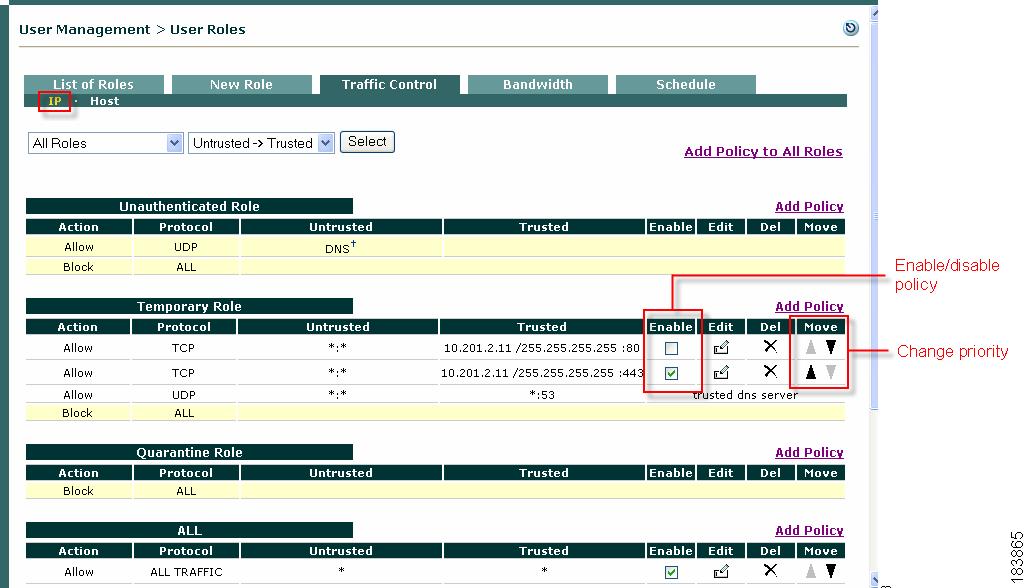
Figure 8-2 List of IP-Based Policies
2.
3.
Note
4.
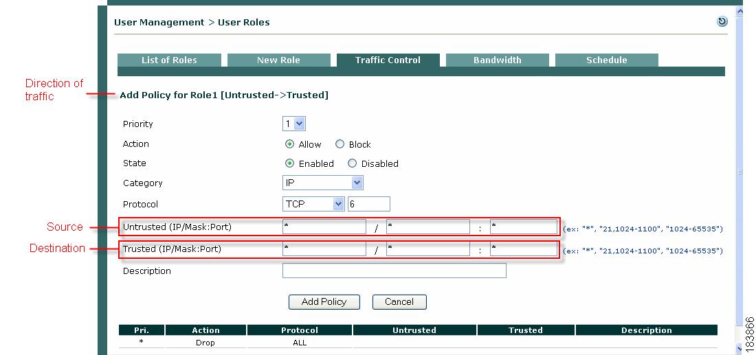
Figure 8-3 Add IP-Based Policy
5.
Note
6.
–
–
7.
–
–
Note
8.
–
–
–
9.
–
–
–
–
–
–
10.
If you chose TCP or UDP as the Protocol, also type the TCP/UDP port number for the application in the Port text field.
Note
11.
Note
•
•
12.
13.
Edit IP-Based Policy
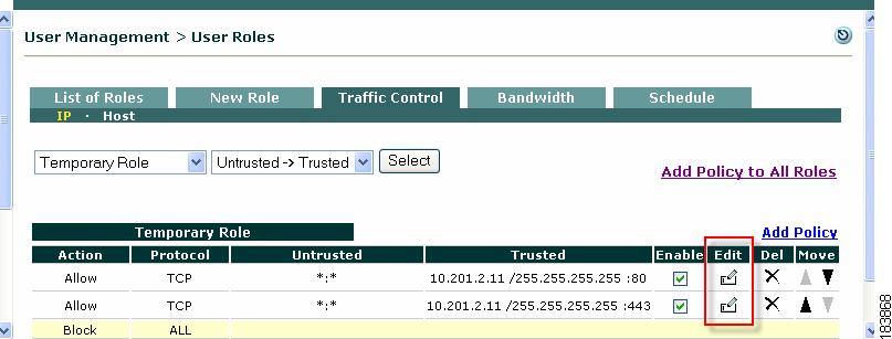
1.
2.
Figure 8-4 Edit IP Policy
3.
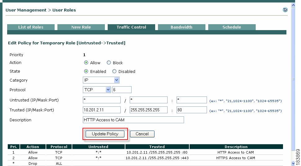
Figure 8-5 Edit IP Policy Form
4.
Note
5.
Note that you cannot change the policy priority directly from the Edit form. To change a Priority, click the Up or Down arrows for the policy in the Move column of the IP policies list page.
Add Global Host-Based Traffic Policies
Default host policies for the Unauthenticated, Temporary, and Quarantine roles are automatically retrieved and updated after an Agent Update or Clean Update is performed from the CAM (see Retrieving Cisco NAC Appliance Updates for complete details on Updates).
You can configure custom DNS host-based policies for a role by host name or domain name when a host has multiple or dynamic IP addresses. Once the host-based policy is setup and all the IP Addresses are resolved, it enables all traffic types to the host machine.
Allowing DNS addresses to be configured per user role facilitates client access to the Windows or antivirus update sites that enable clients to fix their systems if Agent requirements are not met or network scanning vulnerabilities are found. Note that to use any host-based policy, you must first add a Trusted DNS Server for the user role.
Note
•
•
This section describes the following:
•
•
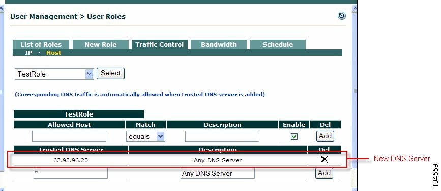
Add Trusted DNS Server for a Role
To enable host-based traffic policies for a role, add a Trusted DNS Server for the role.
1.
1.
2.
Figure 8-6 Add Trusted DNS Server
3.
4.
5.
Note
•
Enable Default Allowed Hosts
Cisco NAC Appliance provides default host policies for the Unauthenticated, Temporary, and Quarantine roles. Default Host Policies are initially pulled down to your system, then dynamically updated, through performing a Cisco NAC Appliance Update or Clean Update. Newly added Default Host Policies are disabled by default, and must be enabled for each role under User Management > User Roles > Traffic Control > Hosts.
To enable Default Host Policies for user roles:
Step 1
Step 2
Step 3
Step 4
Step 5
Step 6
Step 7
Note
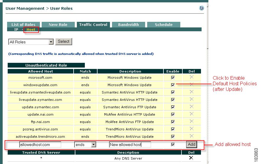
Add Allowed Host
The Allowed Host form allows you to supplement Default Host Policies with additional update sites for the default roles, or create custom host-based traffic policies for any user role.
1.
Figure 8-7 Add Allowed Host
2.
3.
4.
5.
6.
7.
Note
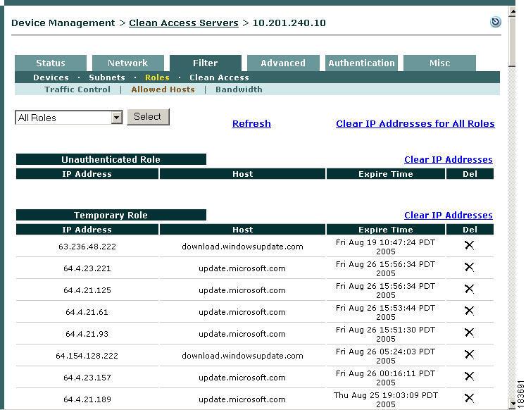
View IP Addresses Used by DNS Hosts
You can view the IP addresses used for the DNS host when clients connect to the host to update their systems. Note that these IP addresses are viewed per Clean Access Server from the CAS management pages.
1.
2.
3.
4.
Figure 8-8 View Current IP Addresses for All Roles
Tip
Proxy Servers and Host Policies
You can allow users to access only the host sites enabled for a role (e.g. Temporary or Quarantine users that need to meet requirements) when a proxy server specified on the CAS is used.
Note that proxy settings are local policies configured on the CAS using the CAS management pages, and the following pages must be configured to enable this feature:
•
•
(the Parse Proxy Traffic option must be enabled)For complete details, see the Cisco NAC Appliance - Clean Access Server Configuration Guide, Release 4.9(2).
See also Proxy Settings for related information.
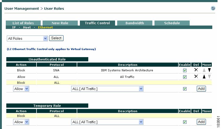
Add Global Layer 2 Ethernet Traffic Policies
Note
You can configure traffic policies for all the default roles already present in the system (Unauthenticated, Temporary, Quarantine). You will need to create normal login user roles first before you can configure traffic policies for them (see Chapter 6 "User Management: Configuring User Roles and Local Users.")
1.
Figure 8-9 Layer 2 Ethernet Traffic Control Policies
2.
3.
Note
4.
5.
After you "Add" a traffic control policy, the CAM automatically populates the Description column for the entry with the description of the option you specified in the Protocol dropdown menu.
Control Bandwidth Usage
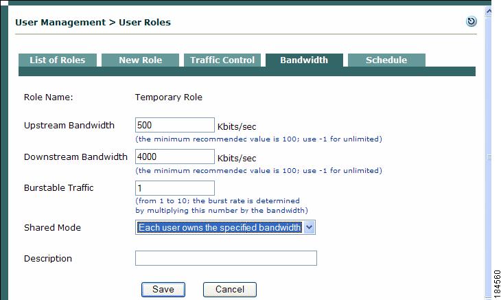
Cisco NAC Appliance lets you control how much network bandwidth is available to users by role. You can independently configure bandwidth management using global forms in the CAM as needed for system user roles, or only on certain Clean Access Servers using local forms. However, the option must first be enabled on the CAS for this feature to work. You can also specify bandwidth constraints for each user within a role or for the entire role.
For example, for a CAM managing two CASs, you can specify all the roles and configure bandwidth management on some of the roles as needed (e.g. guest role, quarantine role, Temporary role, etc.). If bandwidth is only important in the network segment where CAS1 is deployed and not on the network segment where CAS2 is deployed, you can then turn on bandwidth management on CAS1 but not CAS2.
With bursting, you can allow for brief deviations from a bandwidth constraint. This accommodates users who need bandwidth resources intermittently (for example, when downloading and reading pages), while users attempting to stream content or transfer large files are subject to the bandwidth constraint.
By default, roles have a bandwidth policy that is unlimited (specified as -1 for both upstream and downstream traffic).
To configure bandwidth settings for a role:
1.
2.
Note
3.
Figure 8-10 Bandwidth Form for User Role
Note
4.
5.
The Burstable Traffic field is a traffic burst factor used to determine the "capacity" of the bucket. For example, if the bandwidth is 100 Kbps and the Burstable Traffic field is 2, then the capacity of the bucket will be 100Kb*2=200Kb. If a user does not send any packets for a while, the user would have at most 200Kb tokens in his bucket, and once the user needs to send packets, the user will be able to send out 200Kb packets right away. Thereafter, the user must wait for the tokens coming in at the rate of 100Kbps to send out additional packets. This can be thought of as way to specify that for an average rate of 100Kbps, the peak rate will be approximately 200Kbps. Hence, this feature is intended to facilitate bursty applications such as web browsing.
6.
–
–
7.
8.
The bandwidth setting is now applicable for the role and appears in the Bandwidth tab.
Note
Configure User Session and Heartbeat Timeouts
Timeout properties enhance the security of your network by ensuring that user sessions are terminated after a configurable period of time. The are three main mechanisms for automated user timeout:
•
This section describes the Session and Heartbeat Timers.
Session Timer
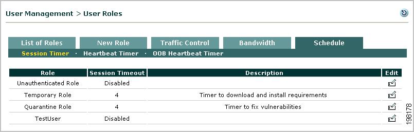
The Session Timer is an absolute timer that is specific to the user role. If a Session Timer is set for a role, a session for a user belonging to that role can only last as long as the Session Timer setting. The Session Timer has a built-in value of 5 minutes that gets added to the configured session timeout value specific to the user role. A user session corresponding to a user role gets cleared at the end of configured session timeout + built-in 5 minute value. For example, if user A logs in at 1:00pm and user B logs in at 1:30pm, and if both belong to role Test with Session Timer set for 115 minutes, user A will be logged out at 3:00pm and user B will be logged out at 3:30pm. When session timeouts, the user is dropped regardless of connection status or activity.
Note
Heartbeat Timer
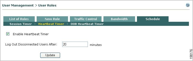
The Heartbeat Timer sets the number of minutes after which a user is logged off the network if unresponsive to ARP queries from the Clean Access Server. This feature enables the CAS to detect and disconnect users who have left the network (e.g. by shutting down or suspending the machine) without actually logging off the network. Note that the Heartbeat Timer applies to all users, whether locally or externally authenticated.
The connection check is performed via ARP query rather than by pinging. This allows the heartbeat check to function even if ICMP traffic is blocked. The CAS maintains an ARP table for its untrusted side which houses all the machines it has seen or queried for on the untrusted side. ARP entries for machines are timed out through normal ARP cache timeout if no packets are seen from the particular machine. If packets are seen, their entry is marked as fresh. When a machine no longer has a fully resolved entry in the CAS's ARP cache and when it does not respond to ARPing for the length of the Heartbeat Timer setting, the machine is deemed not to be on the network and its session is terminated.
In-Band (L2) Sessions
For In-Band configurations, a user session is based on the client MAC and IP address and persists until one of the following occurs:
•
•
•
•
•
OOB (L2) and Multihop (L3) Sessions
The Session Timer works the same way for multi-hop L3 In-Band deployments as for L2 (In-Band or Out-of-Band) deployments.
For L3 deployments, user sessions are based on unique IP address rather than MAC address.
The Heartbeat Timer behaves as inactivity/idle timer for L3 deployments in addition to L2 deployments. For L3 deployments, the Heartbeat Timer now behaves as described in the following cases:
•
If the Clean Access Servers sees no packets from the user for the duration of time that the heartbeat timer is set to, then the user will be logged out. Even if the user's machine is connected to the network but does not send a single packet on the network that reaches the CAS, it will be logged out. Note that this is highly unlikely because modern systems send out many packets even when the user is not active (e.g. chat programs, Windows update, AV software, ads on web pages, etc.)
•
In this scenario, if a device is connected to the network the router will perform proxy ARP for the device's IP address. Otherwise, if a device is not connected to the network, the router does not perform proxy ARP. Typically only VPN concentrators behave in this way. In this case, if the Clean Access Server sees no packets, the CAM/CAS attempts to perform ARP for the user. If the router responds to the CAS because of proxy ARP, the CAM/CAS will not logout the user. Otherwise, if the router does not respond to the CAS, because the device is no longer on the network, the CAM/CAS will log out the user.
•
In this scenario, the router/VPN concentrator performs proxy ARP irrespective of whether individual devices are connected. In this case, the Heartbeat Timer behavior is unchanged, and the CAM/CAS never log out the user.
Note
•
Session Timer / Heartbeat Timer Interaction
•
•
•
•
•
•
For additional details, see Interpreting Active Users.
Configure Session Timer (per User Role)
Step 1
Figure 8-11 Session Timer
Step 2
Step 3
Step 4
Step 5
Configure Heartbeat Timer (User Inactivity Timeout)
Step 1
Figure 8-12 Heartbeat Timer
Step 2
Step 3
Step 4
Note that logging a user off the network does not remove them from the Certified Devices List. However, removing a user from the Certified Devices List also logs the user off the network. An administrator can drop users from the network individually or terminate sessions for all users at once. For additional details see Clear Certified or Exempt Devices Manually and Interpreting Event Logs.
Note
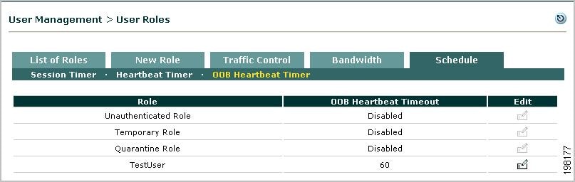
Configure OOB Heartbeat Timer (per User Role)
Step 1
Note
Note
Caution
Figure 8-13 OOB Heartbeat Timer
Step 2
Step 3
Step 4
Configure Policies for Agent Temporary and Quarantine Roles
This section demonstrates typical traffic policy and session timeout configuration needed to:
•
•
Configure Agent Temporary Role
Users who fail a system check are assigned to the Agent Temporary role. This role is intended to restrict user access to only the resources needed to comply with the Agent requirements.
Unlike Quarantine roles, there is only one Agent Temporary role in the Cisco NAC Appliance system. The role can be fully edited, and is intended as single point for aggregating the traffic control policies that allow users to access required installation files. If the Temporary role is deleted, the Unauthenticated role is used by default. The name of the role that is used for the Temporary role (in addition to the version of the Agent) is displayed under Device Management > Clean Access > Clean Access Agent > Distribution.
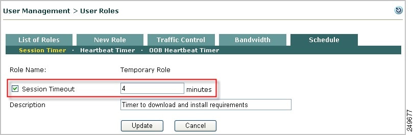
Both session timeout and traffic policies need to be configured for the Temporary role. The Temporary role has a default session timeout of 4 minutes, which can be changed as described below. The Temporary and quarantine roles have default traffic control policies of Block All traffic from the untrusted to the trusted side. Keep in mind that while you associate requirements (required packages) to the normal login roles that users attempt to log into, clients will need to meet those requirements while still in the Temporary role. Therefore, traffic control policies need to be added to the Temporary role to enable clients to access any required software installation files from the download site(s).
Note
Configuring Agent-Based Posture Assessment provides complete details on Agent Requirement configuration. See also User Role Types for additional information.
Configure Session Timeout for the Temporary Role
1.
2.
Figure 8-14 Schedule Tab
3.
4.
Figure 8-15 Session Timer—Temporary Role
5.
6.
7.
8.
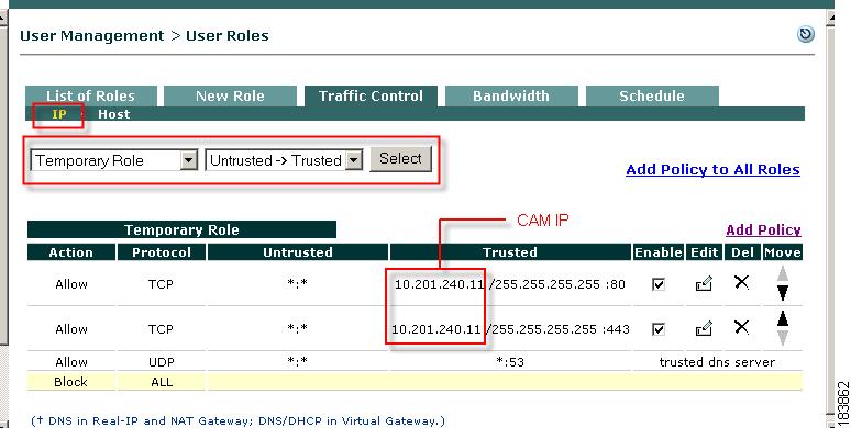
Configure Traffic Control Policies for the Temporary Role
9.
10.
Figure 8-16 IP Traffic Policies—Temporary Role
11.
12.
–
Configure Network Scanning Quarantine Role
See Chapter 12 "Configuring Network Scanning" for complete details on network scanning configuration.
Cisco NAC Appliance can assign a user to a quarantine role if it discovers a serious vulnerability in the client system. The role is a mechanism intended to give users temporary network access to fix their machines. Note that quarantining vulnerable users is optional. Alternatives include blocking the user or providing them with a warning. If you do not intend to quarantine vulnerable users, you can skip this step.
Create Additional Quarantine Role
By default, the system provides a default Quarantine role with a session time out of 4 minutes that only needs to be configured with traffic policies. The following describes how to create an additional quarantine role, if multiple quarantine roles are desired.
1.
2.
3.
4.
5.
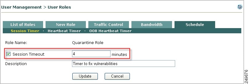
Configure Session Timeout for Quarantine Role
By default, the system provides a default Quarantine role with a session time out of 4 minutes. The following steps describe how to configure the session timeout for a role.
1.
2.
3.
Figure 8-17 Session Timer—Quarantine Role
4.
5.
6.
7.
Setting these parameters to a relatively small value helps the CAS detect and disconnect users who have restarted their computers without logging out of the network. Note that the Session Timer value you enter here may need to be refined later, based on test scans and downloads of the software you will require.
Note
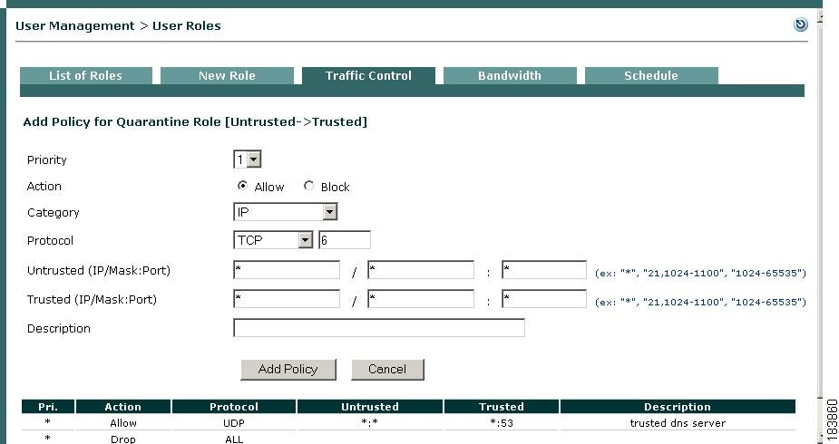
Configure Traffic Control Policies for the Quarantine Role
1.
2.
3.
Figure 8-18 Add Policy—Quarantine Role
4.
–
–
5.
–
After configuring the quarantine role, you can apply it to users by selecting it as their quarantine role in the Block/Quarantine users with vulnerabilities in role option of the General Setup tab. For details, see Client Login Overview.
When finished configuring the quarantine role, load the scan plugins as described in Load Nessus Plugins into the Clean Access Manager Repository.
Example Traffic Policies
This section describes the following:
•
•
•
Allowing Authentication Server Traffic for Windows Domain Authentication
If you want users on the network to be able to authenticate to a Windows domain prior to authenticating to the Cisco NAC Appliance, the following minimum policies allow users in the Unauthenticated role access to AD (NTLM) login servers:
Allow TCP *:* Server/255.255.255.255: 88
Allow UDP *:* Server/255.255.255.255: 88
Allow TCP *:* Server/255.255.255.255: 389
Allow UDP *:* Server/255.255.255.255: 389
Allow TCP *:* Server/255.255.255.255: 445
Allow UDP *:* Server/255.255.255.255: 445
Allow TCP *:* Server/255.255.255.255: 135
Allow UDP *:* Server/255.255.255.255: 135
Allow TCP *:* Server/255.255.255.255: 3268
Allow UDP *:* Server/255.255.255.255: 3268
Allow TCP *:* Server/255.255.255.255: 139
Allow TCP *:* Server/255.255.255.255: 1025
Allowing Traffic for Enterprise AV Updates with Local Servers
In order to allow definition updates for enterprise antivirus products, such as Trend Micro OfficeScan, the Temporary role needs to be configured to allow access to the local server for automatic AV definition updates.
For Trend Micro OfficeScan, the Temporary role policy needs to allow access to the local server with AutoPccP.exe. The Agent calls the Trend client locally, and the Trend client in turn runs the AutoPccP.exe file either on a share drive (located at \\<trendserverip\ofcscan\Autopccp.exe) or through HTTP (depending on your TrendMicro configuration) and downloads the AV patches.
Allowing Gaming Ports
To allow gaming services, such as Microsoft Xbox Live, Cisco recommends creating a gaming user role and to add a filter for the device MAC addresses (under Device Management > Filters > Devices > New) to place the devices into that gaming role. You can then create traffic policies for the role to allow traffic for gaming ports.
Microsoft Xbox
The following are suggested policies to allow access for Microsoft Xbox ports:
•
•
•
•
•
•
Other Game Ports
Table 8-1 shows suggested policies to allow access for other game ports (such as PlayStation).
Table 8-1 Traffic Policies for Other Gaming Ports 1
2300-2400
UDP
4000
TCP, UDP
4000
TCP, UDP
80
TCP
2300
UDP
6073
UDP
2302-2400
UDP
33334
UDP
33335
TCP
6667
TCP
3783
TCP
27900
TCP
28900
TCP
29900
TCP
29901
TCP
27015
TCP
2213 + 1 for each client (i.e. first computer is 2213, second computer is 2214, third computer is 2215, etc.)
TCP
6073
TCP
2302-2400
UDP
27999
TCP
28000
TCP
28805-28808
TCP
9999
TCP
47624
TCP
2300-2400
TCP
2300-2400
UDP
6073
UDP
2302-2400
UDP
47624
TCP
2300-2400
TCP
2300-2400
UDP
5120-5300
UDP
6500
UDP
27900
UDP
28900
UDP
3782
TCP
3782
UDP
27910
TCP, UDP
6073
UDP
2302-2400
UDP
47624
TCP
2300-2400
TCP
2300-2400
UDP
4000
TCP
7777
TCP, UDP
4000
TCP
27015-27020
TCP
6667
TCP
28800-29000
TCP
1 See also http://www.us.playstation.com/support.aspx?id=installation/networkadaptor/415013907.html for additional details.
For additional details, see:
•
•
Adding Traffic Policies for Default Roles
Create Untrusted -> Trusted traffic policies for the default roles (Unauthenticated, Temporary, and Quarantine) to allow users access to any of the resources described below.
Unauthenticated Role
If customizing the web login page to reference logos or files on the CAM or external URL, create IP policies to allow the Unauthenticated role HTTP (port 80) access to the CAM or external server. (See also Upload a Resource File and Create Content for the Right Frame for details.)
Agent Temporary Role
•
Note
•
•
•
Quarantine Role
•
•
•
Table 8-2 summarize resources, roles and example traffic policies for system roles
For further details, see:
•
•
•
Figure 8-19 Example Traffic Policies for File Distribution Requirement (File is on CAM)
Troubleshooting Host-Based Policies
For host-based policies, the CAS needs to see DNS responses in order to allow the traffic. If having trouble with host-based policies, check the following:
•
•
•
•
•
•
•