-
Cisco NAC Appliance - Clean Access Manager Configuration Guide, Release 4.9(2)
-
About This Guide
-
Introduction
-
Device Management: Adding Clean Access Servers, Adding Filters
-
Switch Management: Configuring Out-of-Band Deployment
-
Wireless LAN Controller Management: Configuring Wireless Out-of-Band Deployment
-
Configuring User Login Page and Guest Access
-
User Management: Configuring User Roles and Local Users
-
User Management: Configuring Authentication Servers
-
User Management: Traffic Control, Bandwidth, Schedule
-
Configuring Cisco NAC Appliance for Agent Login and Client Posture Assessment
-
Cisco NAC Appliance Agents
-
Monitoring and Troubleshooting Agent Sessions
-
Configuring Network Scanning
-
Monitoring Event Logs
-
Administering the CAM
-
Error and Event Log Messages
-
API Support
-
MIB Support
-
Open Source License Acknowledgements
-
 Feedback
Table Of Contents
Switch Management: Configuring Out-of-Band Deployment
Network Recovery for "Off Line" Out-of-Band Switches
Out-of-Band Virtual Gateway Deployment
Out-of-Band Real-IP Gateway Deployment
Flow for Out-of-Band Real-IP Gateway Mode
Configure Your Network for Out-of-Band
Example Switch Configuration Steps
OOB Network Setup/Configuration Worksheet
Configure OOB Switch Management on the CAM
Add Out-of-Band Clean Access Servers and Configure Environment
Configure Global Device Filters to Ignore IP Phone MAC Addresses
Manage Individual Ports (MAC Notification)
Manage Individual Ports (Linkup/Linkdown)
Assign a Port Profile to Multiple Ports Simultaneously
Configure Access to Authentication VLAN Change Detection
Wired and Wireless User List Summary
OOB Switch Trunk Ports After Upgrade
OOB Error: connected device <client_MAC> not found
Message Not Within Time Window
Switch Management: Configuring Out-of-Band Deployment
This chapter describes how to configure Cisco NAC Appliance for Out-of-Band (OOB) deployment. Topics include:
•
Configure Your Network for Out-of-Band
•
•
See Cisco NAC Appliance - Clean Access Server Configuration Guide, Release 4.9(2) for additional information on L3 OOB deployment.
Overview
In a traditional In-Band Cisco NAC Appliance deployment, all network traffic to or from clients goes through the Clean Access Server. For high throughput or highly routed environments, a Cisco NAC Appliance Out-of-Band (OOB) deployment allows client traffic to pass through the Cisco NAC Appliance network only in order to be authenticated and certified before being connected directly to the access network. This section discusses the following topics:
In-Band Versus Out-of-Band
Table 3-1 summarizes different characteristics of each type of deployment.
Table 3-1 In-Band vs. Out-of-Band Deployment
The Clean Access Server (CAS) is always inline with user traffic (both before and following authentication, posture assessment and remediation). Enforcement is achieved through being inline with traffic.
The Clean Access Server (CAS) is inline with user traffic only during the process of authentication, assessment and remediation. Following that, user traffic does not come to the CAS. Enforcement is achieved through the use of SNMP to control switches and VLAN assignments to ports.
The CAS can be used to securely control authenticated and unauthenticated user traffic by using traffic policies (based on port, protocol, subnet), bandwidth policies, and so on.
The CAS can control user traffic during the authentication, assessment and remediation phase, but cannot do so post-remediation since the traffic is Out-of-Band.
Does not provide switch port level control.
Provides port-level control by assigning ports to specific VLANs as necessary.
In-Band deployment is supported when deploying for wireless networks.
Wireless OOB requires a specific network topology and configuration. For more information, see Chapter 4 "Wireless LAN Controller Management: Configuring Wireless Out-of-Band Deployment."
Cisco NAC Appliance In-Band deployment with supported Cisco switches is compatible with 802.1x
Cisco does not recommend using 802.1x in an OOB deployment, as conflicts will likely exist between Cisco NAC Appliance OOB and 802.1x to set the VLAN on the switch interfaces/ports.
Out-of-Band Requirements
Out-of-band implementation of Cisco NAC Appliance requires the following to be in place:
•
Supported switch models include:
–
–
–
–
–
–
–
Supported 3750 service modules for Cisco 2800/3800 Integrated Services Routers (ISR) include:
–
–
–
–
–
–
•
Note
•
Note
Clusters are not supported.
Note
SNMP Control
With Out-of-Band deployment, you can add switches to the Clean Access Manager's domain and control particular switch ports using the Simple Network Management Protocol (SNMP). SNMP is an application layer protocol used by network management tools to exchange management information between network devices. Cisco NAC Appliance supports the following SNMP versions:
•
•
•
Write:•
•
•
•
•
•
You first need to configure the switch to send and receive SNMP traffic to/from the Clean Access Manager, then configure matching settings on the Clean Access Manager to send and receive traffic to/from the switch. This will enable the Clean Access Manager to get VLAN and port information from the switch and set VLANs for managed switch ports.
Cisco NAC Appliance also provides support for SHA-1 and 3DES encryption, which is required when configuring SNMP management on a CAM operating in a FIPS 140-2 compliant network.
Network Recovery for "Off Line" Out-of-Band Switches
Cisco NAC Appliance features configurable SNMP polling behavior for Out-of-Band managed switches to ensure that the CAM is able to communicate with switches experiencing network issues when they return to normal operation. Without this function, Cisco NAC Appliance might lose communication with managed switches altogether and remain undetected for some time, requiring the Cisco NAC Appliance administrator to manually step in and clear up the switch behavior and re-establish CAM-to-switch communication.
You can configure this feature using the following settings in the smartmanager_conf table of the CAM CLI:
•
•
Deployment Modes
This section describes Out-of-Band deployment for Virtual Gateway and Real-IP. For all gateway modes, to incorporate Cisco NAC Appliance Out-of-Band in your network, you must add an Authentication VLAN to your network and trunk all Auth VLANs to the untrusted interface of the Clean Access Server.
•
•
Basic Connection
The following diagrams show basic "before" and "after" VLAN settings for a client attached to an Out-of-Band deployment. Figure 3-1 illustrates the In-Band client and Figure 3-2 illustrates the client when Out-of-Band.
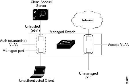
Figure 3-1 Before — Client is In-Band for Authentication/Certification
When an unauthenticated client first connects to a managed port on a managed switch (Figure 3-1), the CAM instructs the switch to change the client port from the authentication (quarantine) VLAN specified in the Port Profile for the port. The switch then sends all traffic from the Auth VLAN client to the untrusted interface of the Clean Access Server (CAS). The client authenticates through the CAS, and/or goes through Nessus Scanning/posture assessment as configured for the role or device. Because the client is on the authentication VLAN, all the client's traffic must go through the CAS and the client is considered to be In-Band.
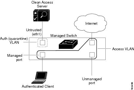
Figure 3-2 After — Client is Out-of-Band After Being Certified
Once the client is authenticated and certified (i.e. on the Certified Devices List), the CAM instructs the switch to change the VLAN of the client port to the Access VLAN specified in the Port Profile of the port (Figure 3-2). Once the client is on the Access VLAN, the switch no longer directs the client's traffic to the untrusted interface of the CAS. At this point the client is on the trusted network and is considered to be Out-of-Band.
In the event the user reboots the client machine, unplugs it from the network, or the switch port goes down, this triggers the switch to send a linkdown trap to the CAM. Thereafter, the client port behavior depends on the Port profile settings for the specific port (see Add Port Profile for details).
If the Cisco NAC Appliance system somehow terminates the OOB client session (if the system administrator is forced to "kick" the user out, for example) and the switch changes the VLAN assignment for the client's access port from the Access VLAN back to the Authentication VLAN, the client machine discovers the VLAN change and, if configured, initiates an IP address refresh/renew to ensure the user stays connected to the network. For details on the polling method and configuration guidelines, see Configure Access to Authentication VLAN Change Detection. (In earlier releases, the client machine would only learn of the switch after the DHCP lease for the client IP address had run out and could not reconnect.)
Note
Out-of-Band Virtual Gateway Deployment
An Out-of-Band Virtual Gateway deployment provides the following benefits:
•
•
In Out-of-Band Virtual Gateway mode, the Clean Access Server uses the VLAN mapping feature to retag the unauthenticated client's allowed traffic (such as DNS or DHCP requests) from the Authentication VLAN to the Access VLAN and vice versa. In this way, no new client IP address is needed when the client is eventually switched to the Access VLAN, because the DHCP-acquired IP address is already paired with the Access VLAN ID.
Note
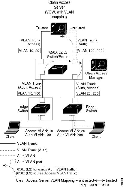
Figure 3-3 illustrates Out-of-Band Virtual Gateway mode using an L3 router/switch. The router/switch receives traffic from the Auth VLAN as Layer 2 traffic and forwards it to the untrusted side of the Clean Access Server. The Virtual Gateway Clean Access Server performs VLAN mapping for allowed traffic (DNS, DHCP) from the Auth VLAN (untrusted interface) to the Access VLAN (trusted interface) and vice versa. The router/switch receives traffic from the Access VLAN as Layer 3 traffic and routes it accordingly. Figure 3-3 illustrates the client authentication and access path for the OOB Virtual Gateway example described below. In this example, the Authentication VLAN is 100, and the Access VLAN is 10.
Figure 3-3 Out-of-Band VGW Mode: Catalyst 6500 Series Example
Flow for OOB VGW Mode
1.
2.
Note
3.
4.
5.
Note
6.
7.
8.
9.
10.
11.
Note
12.
•
•
•
Note also that:
•
•
•
•
For additional configuration information, see the "Understanding VLAN Settings" and "VLAN Mapping in Virtual Gateway Mode" sections of the Cisco NAC Appliance - Clean Access Server Configuration Guide, Release 4.9(2).
Out-of-Band Real-IP Gateway Deployment
In Out-of-Band Real-IP gateway deployment, the client IP address has to change when the port is changed from the Auth VLAN to the Access VLAN.
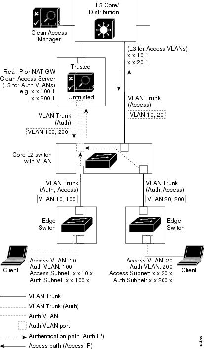
Figure 3-4 illustrates the sequence described below. In this example, the Authentication VLAN is 100, and the Access VLAN is 10.
Figure 3-4 Out-of-Band Real-IP Gateway Deployment
Flow for Out-of-Band Real-IP Gateway Mode
1.
2.
Note
3.
4.
5.
6.
7.
8.
Note
9.
•
•
•
Note
•
L3 Out-of-Band Deployment
For details on L3 OOB, refer to the following sections:
•
•
Configure Your Network for Out-of-Band
The Clean Access Manager (CAM) manages Out-of-Band Clean Access Servers (CASs) and switches through the admin network. The trusted interface of the CAS connects to the admin/management network, and the untrusted interface of the CAS connects to the managed client network.
When a client connects to a managed port on a managed switch, the port is set to the authentication VLAN and the traffic to/from the client goes through the Clean Access Server. After the client is authenticated and certified through the Clean Access Server, the port connected to the client is changed to the access VLAN. Once on the access VLAN, traffic to and from certified clients bypasses the Clean Access Server.
In most OOB deployments (except L2 OOB Virtual Gateway where the Default Access VLAN is the Access VLAN in the Port profile), the client needs to acquire a different IP address from the Access VLAN after posture assessment.
For Real-IP Gateway setup, the client port is bounced to prompt the client to acquire a new IP address from the admin/access VLAN.
The next sections describe the configuration steps needed to set up your OOB deployment:
•
•
Note
Configure Your Switches
This section describes the steps needed to set up switches to be used with Cisco NAC Appliance Out-of-Band.
•
•
Configuration Notes
The following considerations should be taken into account when configuring switches for OOB:
•
–
–
This will prevent unnecessary issues when the Default Port Profile for the switch has been configured as a managed/controlled port profile.
•
–
–
•
•
(config)# snmp ifmib ifindex persist•
•
•
•
•
•
•
•
•
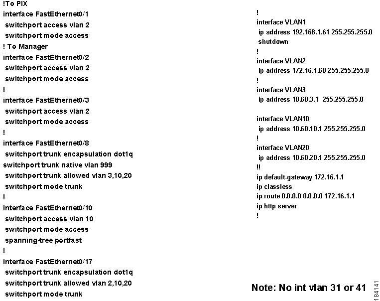
Example Switch Configuration Steps
Step 1
The trusted interface of the CAS is connected to the trunk port for Access VLANs 10, 20 and the untrusted interface of the CAS is connected to the trunk port for Auth VLANs 31, 41.
Refer the switch documentation for details on configuring your specific switch model.
Step 2
Step 3
(config)# no int vlan 31(config)# vlan 31The first command turns off the interface and the second ensures VLAN 31 (Auth VLAN) is in the VLAN database table.You will also need to Enable VLAN Mapping in the CAS as described in Figure 3-8.
Note
Step 4
Step 5
(config)# snmp-server location <location_string>(config)# snmp-server contact <admin_contact_info>
Note
Step 6
•
(config)# snmp-server community c2950_read RO•
(config)# snmp-server view v1default iso included(config)# snmp-server group c2950_group v3 auth read v1default write v1default(config)# snmp-server user c2950_user c2950_group v3 auth md5 c2950_authFor SNMP V3 read, create SNMP V3 contexts for the VLANs that are used in the switch. To get the contexts that are present in the switch, run the following command in the switch:
access-switch# sh snmp contextThe output will be similar to the following:
vlan-1vlan-2vlan-3vlan-8vlan-9........vlan-1005Create SNMP V3 contexts for the VLANs that are used. For example, if the vlan-8 and vlan-9 are being used, then the command to create the context is as follows:
(config)# snmp-server group c2950_group v3 auth context vlan-8(config)# snmp-server group c2950_group v3 auth context vlan-9The above example is to create SNMP V3 context when the security method is set to AuthNoPriv. You need to provide the commands based on the security level as follows:
•
•
•
Step 7
•
(config)# snmp-server community c2950_write RW•
For auth (username: "c2950_user;" password: "c2950_auth"):
(config)# snmp-server view v1default iso included(config)# snmp-server group c2950_group v3 auth read v1default write v1default notify vldefault(config)# snmp-server user c2950_user c2950_group v3 auth md5 c2950_authFor priv (username: "c2950_user;" password: "c2950_priv"):
(config)# snmp-server view v1default iso included(config)# snmp-server group c2950_group v3 priv read v1default write v1default notify vldefault(config)# snmp-server user c2950_user c2950_group v3 auth md5 c2950_auth priv des c2950_ privStep 8
To support a variety of switch configurations, Cisco NAC Appliance supports switches using both MAC Change Notification and MAC Move Notification traps. If enabling MAC notification traps, the MAC address table aging-time must be set to a non-zero value. Cisco recommends setting the MAC address table aging-time to at least 3600 seconds for switches that have limited space for MAC addresses, and to a higher value (e.g. 1000000) if your switches support a sufficiently large number of MAC entries. If a switch supports MAC notification traps, Cisco NAC Appliance uses the MAC change notification/MAC move notification trap by default, in addition to linkdown traps (to remove users). If the switch does not support MAC change notification/MAC move notification traps, the Clean Access Manager uses linkup/linkdown traps only.
(config)# snmp-server enable traps mac-notification(config)# snmp-server enable traps snmp linkup linkdown(config)# mac-address-table aging-time 3600Step 9
Note
To support a variety of switch configurations, Cisco NAC Appliance supports switches using both MAC Change Notification and MAC Move Notification traps.
•
(config)# snmp-server host 172.16.1.61 traps version 1 cam_v1 udp-port 162
mac-notification snmp
•
(config)# snmp-server host 172.16.1.61 traps version 2c cam_v2 udp-port 162
mac-notification snmp
•
•
For auth (SNMP username/password is "cam_user"/"cam_auth")
(config)# snmp-server group cam_group v3 auth read v1default write v1default notify
v1default
(config)# snmp-server user cam_user cam_group v3 auth md5 cam_auth(config)# snmp-server host 172.16.1.61 traps version 3 auth cam_user udp-port 162 mac-notification snmpFor priv (SNMP username/password is "cam_user"/"cam_priv")
(config)# snmp-server group cam_group v3 priv read v1default write v1default notify
v1default
(config)# snmp-server user cam_user cam_group v3 auth md5 cam_auth priv des cam_priv(config)# snmp-server host 172.16.1.61 traps version 3 priv cam_user udp-port 162 mac-notification snmpStep 10
•
(config)# spanning-tree portfast default•
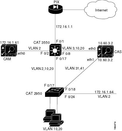
(config-if)# spanning-tree portfastFigure 3-5 illustrates an example OOB setup.
Figure 3-5 Example Physical Setup
Note
Figure 3-6 Example L3 Switch Configuration
OOB Network Setup/Configuration Worksheet
Table 3-2 summarizes information needed to configure switches and the Clean Access Manager.
List of MIBs and OIDs
Table 3-3 lists the MIBs and OIDs used by NAC for both wireless controllers and switches.These OIDs and their corresponding MIBs should be implemented by the device that is being added to NAC.
Configure OOB Switch Management on the CAM
This section describes the web admin console configuration steps to implement Out-of-Band. In general, you first configure Group, Switch, and Port profiles, as well as the Clean Access Manager's SNMP Receiver settings, under OOB Management > Profiles. After profiles are configured, add the switches you want to control to the Clean Access Manager's domain under OOB Management > Devices, and apply the profiles to the switches.
After switches are added, the ports on the switch are discovered, and the Port and Config icons and pages for each switch appear on OOB Management > Devices > Devices > List.
Clicking the manage Ports icon brings up the Ports tab. The Ports page is where you apply a managed Port Profile to a specific port(s) to configure how a client's traffic is temporarily routed through the CAS for authentication/certification before being allowed on the trusted network.
The configuration sequence is as follows:
1.
2.
3.
Add Out-of-Band Clean Access Servers and Configure Environment
Note
Almost all the CAM/CAS configuration for Out-of-Band deployment is done directly in the OOB Management module of the web admin console. Apart from the OOB Management module configuration, OOB setup is almost exactly the same as traditional In-Band setup, except for the following differences:
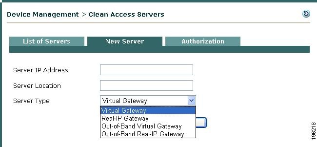
Step 1
Figure 3-7 Add New OOB Server
The Out-of-Band Server Types appear in the dropdown menu to add a new Clean Access Server:
•
•
The Clean Access Server itself must be either In-Band or Out-of-Band. The Clean Access Manager can control both In-Band and Out-of-Band CASs in its domain.
Note
•
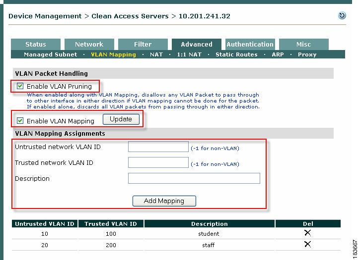
Step 2
Figure 3-8 Enable VLAN Mapping for Out-of-Band Virtual Gateways
Step 3
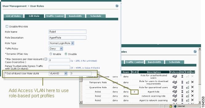
Figure 3-9 Configure User Role with Access VLAN
Note
Step 4
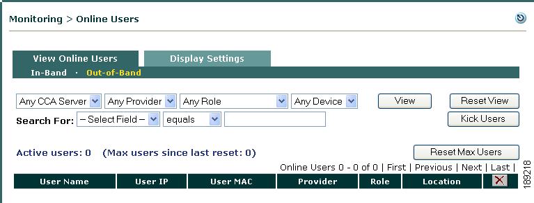
Figure 3-10 View Out-of-Band Online Users
Configure Global Device Filters to Ignore IP Phone MAC Addresses
An important feature of any OOB configuration is to ensure IP phones through which client machines connect to the network do not inadvertently terminate the client connection when MAC notification events from the IP phone initiate a change in the network connection like a VLAN change. To do this:
•
•
For more information, see Device Filters for Out-of-Band Deployment Using IP Phones. For detailed configuration instructions, see Add Global Device Filter.
Configure Group Profiles
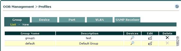
When you first add a switch to the Clean Access Manager's domain (under OOB Management > Devices), a Group profile must be applied to add the new switch. There is a predefined Group profile called default, shown in Figure 3-11. All switches are automatically put in the default group when you add them. You can leave this default Group profile setting, or you can create additional Group profiles as needed. If you are adding and managing a large number of switches, creating multiple Group profiles allow you to filter which sets of devices to display from the list of switches (under OOB Management > Devices > Devices > List).
Figure 3-11 Group Profiles List
Add Group Profile
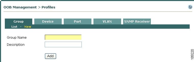
Step 1
Figure 3-12 New Group
Step 2
Step 3
Step 4
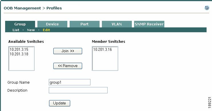
Edit Group Profile
Step 1
Step 2
Figure 3-13 Edit Group
Step 3
Step 4
Note
Configure Switch Profiles
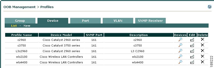
A Switch profile must first be created under OOB Management > Profiles > Device > New, then applied when a new switch is added. A Switch profile classifies switches of the same model and SNMP settings, as shown in Figure 3-14. The Switch profile configures how the CAM will read/write/change port settings, such as Access/Auth VLAN, on a switch of this particular type.
Figure 3-14 Switch Profiles List
The Switch profiles list under OOB Management > Profiles > Device > List provides three icons:
•
•
•
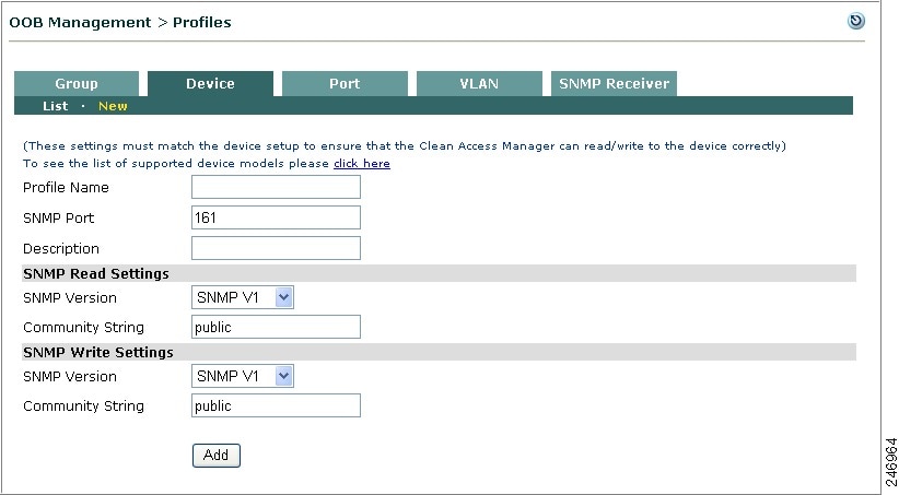
Add Switch Profile
Use the following steps to add a Switch profile.
Step 1
Figure 3-15 New Switch Profile
Step 2
Note
Step 3
Step 4
Note
Step 5
•
•
Step 6
•
•
•
•
Step 7
•
•
Step 8
•
•
•
•
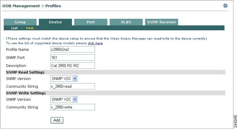
Step 9
Figure 3-16 illustrates a switch profile defining Cisco Catalyst 2950 switches with the same SNMP settings: SNMP V2c with read community string "c2950_read" and write community string "c2950_write."
Figure 3-16 Example Switch Profile
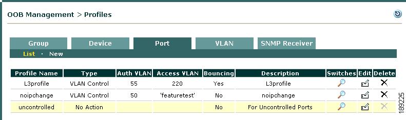
Configure Port Profiles
The Port profile determines whether a port is managed or unmanaged, the Authentication and Access VLANs to use when switching the client port, and other behavior for the port (see Ports Management Page). There are four types of port profiles for switch ports (shown in Figure 3-17):
•
•
•
•
Regular switch ports that are not connected to clients use the unmanaged Port profile. Client-connected switch ports use managed Port profiles. When a client connects to a managed port, the port is set to the authentication VLAN. After the client is authenticated and certified, the port is set to the access VLAN specified in the Port profile (Default Access VLAN, or User Role VLAN, or Initial Port VLAN).
In OOB Real-IP gateway mode, the CAM enables port bouncing to help clients acquire a new IP address after successful authentication and certification. In OOB Virtual Gateway mode, port bouncing is not necessary as the client uses the same IP address after successful authentication and certification.
Note
Figure 3-17 Port Profiles List
Note
Add Port Profile
You will need to add a Port profile for each set of Authentication/Access VLANs you configure on the switch.
Note
Step 1
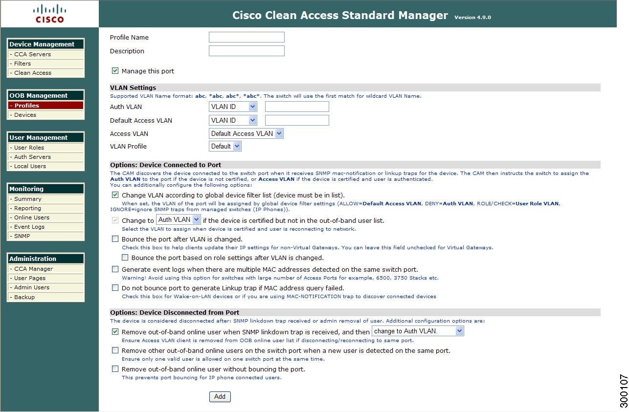
Figure 3-18 New Port Profile
Step 2
Note
Step 3
Step 4
Step 5
•
•
Step 6
•
•
Note
Step 7
•
•
•
Step 8
Note
Port Profile Options when Device is Connected to Port
The CAM discovers the device connected to the switch port from SNMP MAC change notification/MAC move notification or linkup traps received. The port is assigned the Auth VLAN if the device is not certified, or Access VLAN if the device is certified and user is authenticated. You can additionally configure the following options:
Step 9
•
•
•
•
•
Note
Rules configured for MAC addresses on the global Device Filter list have the highest priority for user/device processing in both OOB and IB deployments. See Device Filters for Out-of-Band Deployment for further details.
For more information on In-Band vs. Out-of-Band client machine behavior based on specified Device Filter type, see In-Band and Out-of-Band Device Filter Behavior Comparison.Step 10
•
•
Step 11
•
•
Note
Step 12
Note
Step 13
WarningStep 14
Port Profile Options when Device is Disconnected from Port
A device is considered disconnected after one of the following events occurs:
•
•
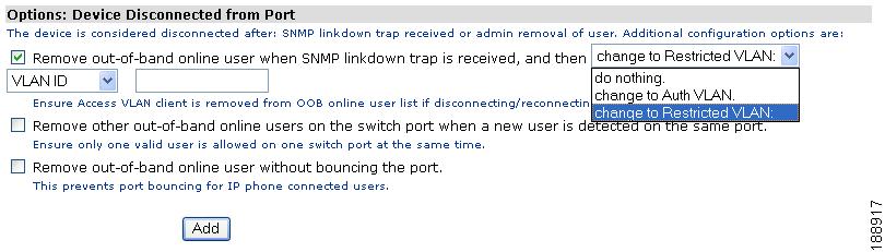
Figure 3-19 Options: Device Disconnected from Port
Step 15
•
Click this option to specify which VLAN the CAM assigns to a switch port after receiving a linkdown trap from the switch when a client disconnects from the Cisco NAC Appliance network. (See Advanced for details on linkdown traps.)
–
Note
–
–
•
This feature enables administrators to remove other online Out-of-Band users on the switch port when a new user is detected on the same port. It also allows for the modification of the port profile if an existing user is seen on a different switchport.
Checking this option ensures that only one valid user is allowed on one switch port at the same time. If an online user (e.g."user1") is currently on a switch port (e.g. "fa0/1" on switch "c2950") and this option is enabled for the Port Profile applied to that port, "user1" will be removed if another user (e.g "user2") signs in from the same switch port or moves to this port from another location.
Note
•
When any user is removed from the OOB Online User list, the port is changed from the Access VLAN to the Authentication VLAN. Also note that users removed from the Certified Device list are also always removed from the Online User list (IB or OOB). If the Remove Out-of-Band online user without bouncing the port option is checked, the port will not be bounced when a user is removed from the OOB Online User list. If this option is not checked, the port will be bounced when a user is removed from the OOB Online User list.
This option is intended to prevent bouncing the switch port to which a client machine is connected via an IP phone. The feature allows Cisco NAC Appliance to authenticate/assess/quarantine/remediate a client machine (laptop/desktop) without affecting the operation of a IP phone connected to the switch port. When this option is checked for OOB Virtual Gateways, the client port will not be bounced when:
–
–
Instead, the port Access VLAN will be changed to the Authentication VLAN.
Step 16
See Manage Switch Ports for further details on Port profiles and the Ports config page.
See Interpreting Event Logs for further details on monitoring online users.
Configure VLAN Profiles
You can use VLAN profiles on your Cisco NAC Appliance to resolve VLAN name-to-VLAN ID mappings while simultaneously ensuring uniform L3 OOB support for multiple access points on your network. VLAN profiles work in conjunction with port profiles to specify the Access VLAN for a user session based on a set of VLAN name-to-VLAN ID mappings. If you have a single access point for remote users on your network, VLAN profiles likely serve very little purpose. If, however, your network includes two, three, or even dozens of different access points, VLAN profiles can help you dynamically assign Access VLAN IDs for remote users based on a "user friendly" VLAN name assignment associated with the user's profile configured on the system.
When a remote user accesses the network for authentication, the Cisco NAC Appliance assigns the user session to an Authentication VLAN before granting network access. Once the user is authenticated, the CAM instructs the access switch (the switch through which the user is accessing the network) to assign a VLAN ID to the managed port, based on Default Access VLAN, User Role VLAN, or Initial Port VLAN definitions.
There are two methods to determine VLAN name-to-VLAN ID mapping criteria:
•
•
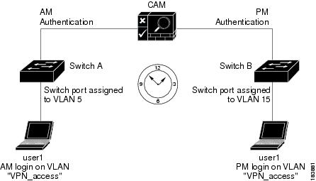
You can configure the CAM to query only the local database, only the switch database, or both sources in the order you specify. When a user logs in to the network from a given access point and has been authenticated, they may be assigned one VLAN ID for one switch and a different VLAN ID for another. Figure 3-20 provides an example of this feature in a remote-access scenario.
Figure 3-20 VLAN Profile Feature Example
1.
2.
3.
4.
5.
6.
7.
8.
9.
As this example demonstrates, the VLAN access name is the same for both sessions, but two separate VLAN profiles on the CAM ensure user1 receives the same level of authentication from both access points on the network.
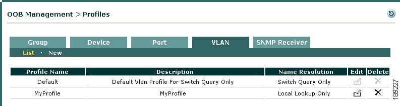
Figure 3-21 illustrates the VLAN Profiles List page.
Figure 3-21 VLAN Profiles
Note
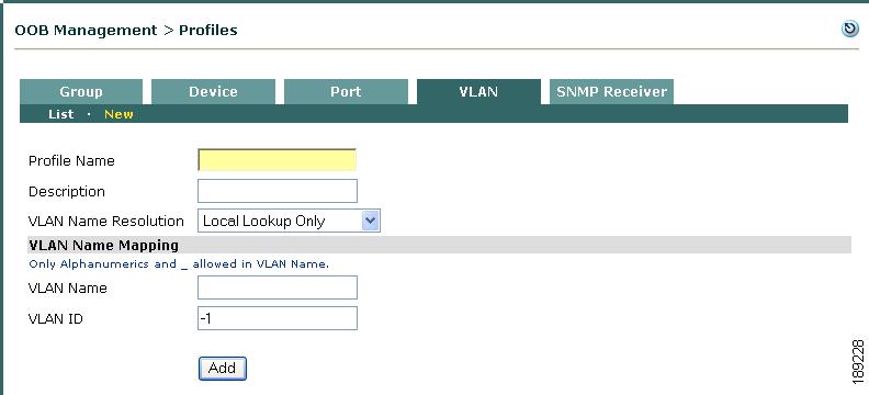
Add VLAN Profile
To create a new VLAN profile:
Step 1
Figure 3-22 New VLAN Profile
Step 2
Step 3
Step 4
•
•
•
Step 5
Step 6
Step 7
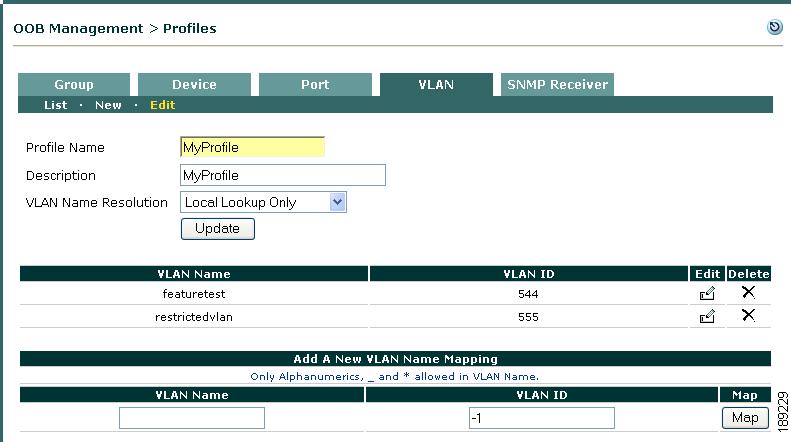
Edit VLAN Profile
To edit an existing VLAN profile:
Step 1
Figure 3-23 VLAN Profiles
Step 2
The Edit VLAN Profile window (Figure 3-24) appears.
Figure 3-24 Edit VLAN Profile
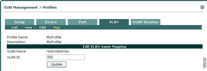
Step 3
Step 4
a.
b.
Figure 3-25 Edit VLAN Name Mapping—VLAN ID
Configure SNMP Receiver
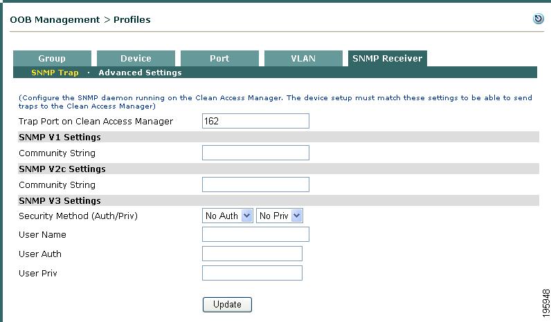
The SNMP Receiver form configures how the SNMP Receiver running on the Clean Access Manager receives and responds to SNMP trap notifications from all managed switches when MAC change notification/MAC move notification or linkup/linkdown user events occur (such as when a user plugs into the network). The configuration on the switch must match the CAM's SNMP Receiver configuration in order for the switch to send traps to the CAM.
Cisco NAC Appliance also provides support for SHA-1 and 3DES encryption, which is required when configuring SNMP management on a CAM operating in a FIPS 140-2 compliant network.
SNMP Trap
This page configures settings for the SNMP traps the CAM receives from all switches. The Clean Access Manager SNMP Receiver can support simultaneous use of different versions of SNMP (V1, V2c, V3) when controlling groups of switches in which individual switches may be using different versions of SNMP.
Step 1
Figure 3-26 CAM SNMP Receiver
Step 2
Step 3
Step 4
Step 5
•
–
–
Note
•
•
•
Step 6
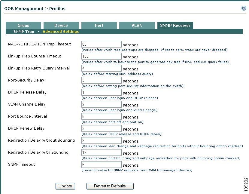
Advanced Settings
This page configures advanced timeout and delay settings for the SNMP traps received and sent by the Clean Access Manager (CAM). To change the default settings, use the following steps. You can use the page to fine-tune settings from their defaults once switches are added and configured.
To Change Default SNMP
Step 1
Figure 3-27 SNMP Receiver > Advanced Settings
Step 2
•
•
•
•
Note
•
•
Note
•
•
•
When the port is not bounced, the total redirection interval that the user experiences is the value of the Redirection Delay without Bouncing field.
Note
•
When the port is bounced, the total redirection interval that the user experiences is the sum of 2 fields: Redirection Delay with Bouncing and Port Bounce Interval.
If the Port Profile requires bouncing the port after the VLAN is changed, then after user login, the user will see "Renewing IP address" page after the sum of the number of seconds specified in this field and the number of seconds specified in the Port Bounce Interval. For example:
Port Bounce (5 seconds) + Redirection Delay (15 seconds) = Redirection interval (20 seconds total)
•
Step 3
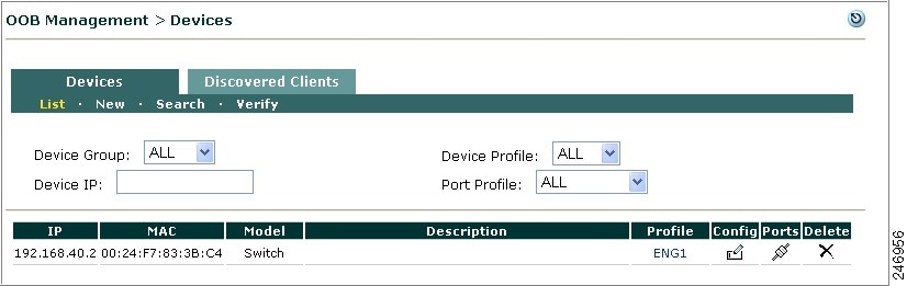
Add and Manage Switches
The pages under the OOB Management > Devices > Devices tab are used to discover and add new managed switches within an IP range, add new managed switches by exact IP address, manage the list of controlled switches, and verify the switches and WLC.
Figure 3-28 List of Switches
The list of switches under OOB Management > Devices > Devices > List displays all switches and WLCs added from the New or Search forms. Switch entries in the list include the switch's IP address, MAC address, Description, and Switch Profile. You can sort the entries on the list by Device Group, Device Profile, or Port Profile dropdowns, or you can simply type a Device IP and hit Enter to search for a switch or WLC by its address. Additionally the List provides one control and three icons:
•
•
•
Note
•
Note
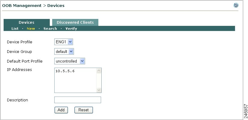
Add New Switch
The New page allows you to add switches when exact IP addresses are already known.
Note
Step 1
Figure 3-29 Add New Switch
Step 2
Step 3
Step 4
Step 5
Step 6
Step 7
Step 8
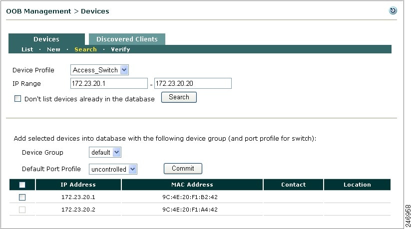
Search New Switches
The Search page allows you to discover and add unmanaged switches within an IP range.
Step 1
Figure 3-30 Search Switches
Step 2
Step 3
Step 4
Step 5
Step 6
Step 7
Note
Step 8
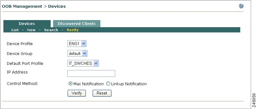
Verify Devices
The Verify page allows you to verify the devices. This utility verifies a device already added to CAM or a new device that is yet to be added to CAM. The device may be a switch or WLC.
Note
Step 1
Figure 3-31 Verify Devices
Step 2
Step 3
Step 4
Step 5
Step 6
Note
•
Note
•
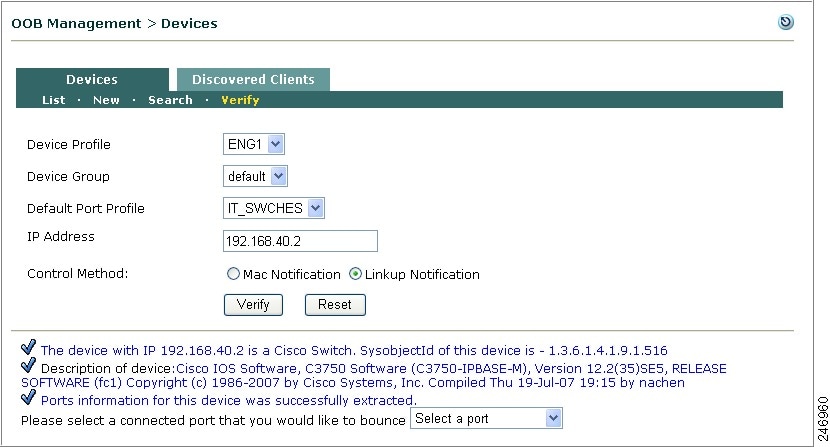
Step 7
The device is verified and the results are displayed at the bottom of the page as shown in Figure 3-32.
Figure 3-32 Verify Devices
- Result
The device status is displayed and you can select a connected port that you would like to bounce from the dropdown.
Discovered Clients
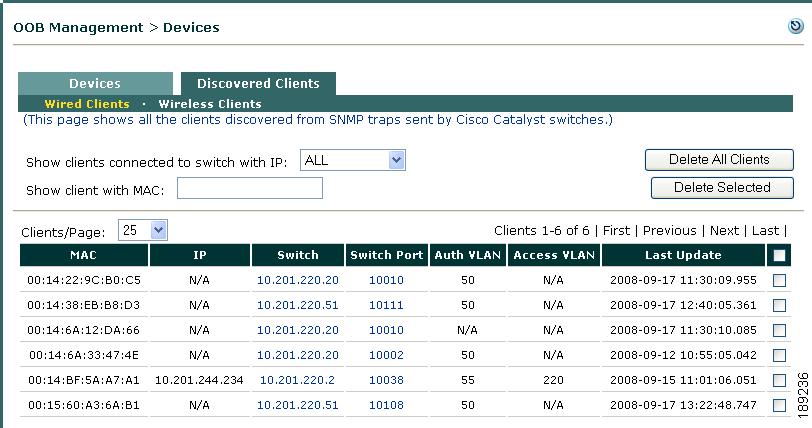
Figure 3-33 shows the OOB Management > Devices > Discovered Clients > Wired Clients page. The Wired Clients page lists all clients discovered by the Clean Access Manager via SNMP MAC change notification/MAC move notification and linkup/linkdown traps. The page records the activities of Out-of-Band clients (regardless of VLAN), based on the SNMP trap information that the Clean Access Manager receives.
When a client connects to a port on the Auth VLAN, a trap is sent and the Clean Access Manager creates an entry on the Wired Clients page. The Clean Access Manager adds a client's MAC address, originating switch IP address, and switch port number to the Out-of-Band Discovered Clients list. Thereafter, the CAM updates the entry as it receives new SNMP trap information for the client.
Removing an entry from the Wired Clients list clears this status information for the Out-of-Band client from the CAM.
Note
Figure 3-33 Discovered Clients
Elements of the page are as follows:
•
•
•
•
•
•
–
–
–
–
–
A value of "N/A" in this column indicates that either the port is unmanaged or the VLAN ID for this MAC address is unavailable from the switch.–
A value of "N/A" in this column indicates the Access VLAN ID is unavailable for the client. For example, if the user is switched to the Auth VLAN but has never successfully logged into Cisco NAC Appliance (due to wrong user credentials), this machine will never have been to the Access VLAN.–
See Out-of-Band Users for additional details on monitoring Out-of-Band users.
Manage Switch Ports
Once a switch is added, the Ports and Config tabs/pages only appear after a switch is added to the OOB Management > Devices > Devices > List.
The Ports page is the central point of management for the ports on a switch. You can apply Port profiles to individual or multiple ports, change VLAN settings, bounce ports, and apply all changes to the switch configuration.
Switch ports that are not connected to clients typically use the unmanaged port profile. Switch ports connected to clients use managed port profiles. After switch ports are configured and the settings are saved by clicking the Update button, the switch ports need to be initialized by clicking the Setup button when the switch supports MAC notification.
Cisco NAC Appliance provides OOB support for Cisco IP Phone deployments where the port is a trunk port and the native VLAN is the data VLAN. The CAM can manage switch trunk ports in addition to switch access ports.
Note
•
•
This prevents unnecessary issues when the Default Port Profile for the switch has been configured as a managed/controlled port profile.
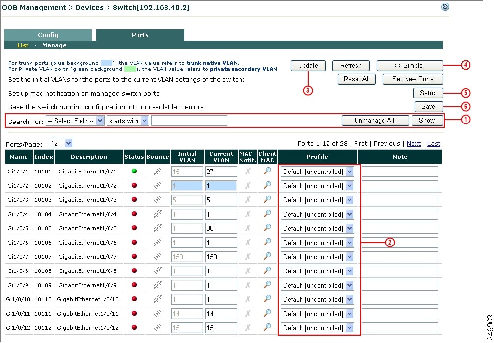
Ports Management Page
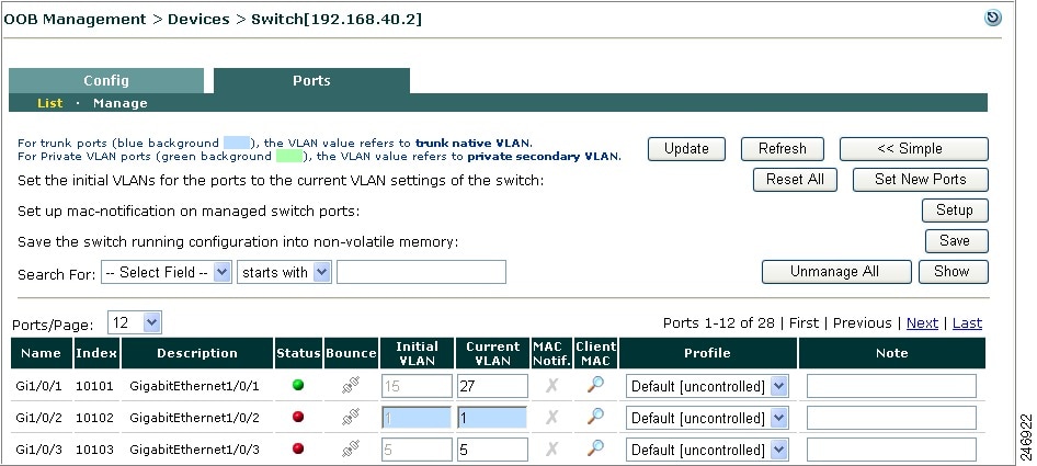
The Ports management page populates information for all Ethernet ports on a switch (see Figure 3-34 and Figure 3-35) according to the information the Clean Access Manager receives from direct SNMP queries. For example, if a switch added to the CAM has 24 Fast Ethernet ports and 2 Gigabit Ethernet uplinks, the Ports tab will display 26 rows, with one entry per port. Trunk ports configured on the switch are distinguished by blue background on the Ports page, and VLAN values for these ports refer to the trunk port native VLAN.
If the switch does not support MAC change notification/MAC move notification traps, the Setup button (Set up mac-notification on managed switch ports) and MAC Notif. column are not displayed on the page. In this case, linkup/linkdown traps must be supported and configured on the switch and Clean Access Manager. See Manage Individual Ports (Linkup/Linkdown) for the Ports management page controls for linkup/linkdown only ports.
Manage Individual Ports (MAC Notification)
This section describes the method you use to manage and/or assign a port profile to an individual switch port. This method works well for a small number of ports, but if you want to assign the same port profile to a large number of ports all at the same time, see Assign a Port Profile to Multiple Ports Simultaneously.
Figure 3-34 Ports Tab
After adding a new switch, set up the Ports configuration page (Figure 3-34) for the switch ports as follows:
Step 1
Step 2
Step 3
Step 4
Step 5
Step 6
•
Click Unmanage All to change all the managed ports to default port profile that was setup for the switch.
•
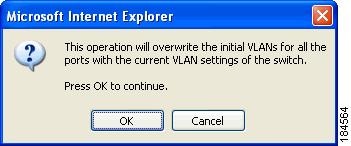
Clicking Reset All copies the switch's Current VLAN values (Current VLAN) for all ports and sets these as the Initial VLAN settings (for access ports) and trunk native VLAN settings (for trunk ports) (Initial VLAN (Initial VLAN Port Profiles only)) on the CAM and on the running configuration of the switch. This button allows you to change the Initial VLAN for all ports at the same time on the switch. Click OK in the confirmation to reset the values:
•
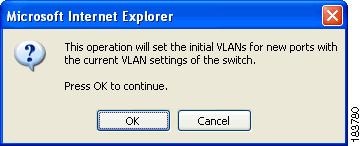
Clicking Set New Ports (Figure 3-34) preserves settings for existing ports, but copies the switch's Current VLAN values for new ports and sets these as Initial VLAN settings (for access ports) and trunk native VLAN settings (for trunk ports) on the CAM and on the switch running configuration. This is useful when new ports are added to a switch, such as when adding a new blade in a Catalyst 4500 series rack. In this case, when the new ports are added, the Initial VLAN column displays "N/A." Clicking Set New Ports copies the values from Current VLAN column to the Initial VLAN column for all "N/A" ports and sets these values on the CAM and switch. The Initial VLAN values for existing ports on the switch (i.e. not "N/A") will not change. Click OK in the confirmation to set the new values.
•
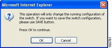
For switches that support MAC change notification/MAC move notification traps, click the Setup button after updating the CAM to set up MAC notification on managed switch ports and save the running configuration of the switch. Click OK to initialize ports on the switch.
•
Click the Save button to save the running configuration into non-volatile memory (startup configuration) on the switch. Click OK in the confirmation.
Note
•
After you configure managed ports by choosing the applicable Port Profile, you must click the Update button to save these settings on the CAM. Clicking Update does the following:
–
–
If the Port profile is configured with the Initial Port VLAN as the Access VLAN and set to "Change to Access VLAN if the device is certified and in the Out-of-Band user list," clicking Update also does the following:
–
–
•
To limit the range of switch ports displayed in the Ports tab view, you can specify search criteria using the Search For filtering functions and specify a text string for which to search. You can specify:
–
–
–
Once you have specified the search criteria, click Show.
•
Port name, for example: Fa0/1, Fa0/24, Gi0/1, Gi0/21 (for Cisco switches)
•
The port number on the switch, for example: 1, 24, 25, 26
•
Type of port, for example: FastEthernet0/1, FastEthernet0/24, GigabitEthernet0/1, GigabitEthernet0/2
•
Connection status of the port.
–
–
•
Clicking this icon bounces an initialized, managed port. A confirmation appears before the port is bounced. Note that this feature is only available for managed ports. A port that is connected but not managed cannot be bounced. By default, this feature is disabled for trunk ports.
•
The Initial VLAN value saved by the CAM for this port. This column is only enabled for managed Port profiles configured with the Initial Port VLAN as the Access VLAN and set to "Change to Access VLAN if the device is certified and in the Out-of-Band user list" (see Add Port Profile). When a switch is added, this column is identical to the Current VLAN column. When new ports are added to a switch, this column displays "N/A" for these ports until the Set New Ports button is clicked (Set New Ports (Initial VLAN Port Profiles only)).
To change the Initial VLAN of a port on-the-fly:
a.
b.
c.
See also: Reset All (Initial VLAN Port Profiles only),Set New Ports (Initial VLAN Port Profiles only), and Save (6).
•
The Current VLAN ID assigned to the port. When a new switch is added, the Current VLAN column reflects the VLAN assignments already configured on the switch by the network administrator. Thereafter, the values in this column are dynamic and reflect the current VLAN assignments on the switch (not necessarily the stored VLAN assignment). For trunk ports, the Current VLAN refers to the native VLAN of the trunk port.
To change the Current VLAN assignment for a port on-the-fly:
a.
b.
c.
See also Reset All (Initial VLAN Port Profiles only),Set New Ports (Initial VLAN Port Profiles only), and Save (6).
•
MAC notification capability. The presence of this column indicates the switch is using SNMP MAC change notification/MAC move notification traps. If the switch does not support MAC notification traps, or if linkup notification is chosen in the Advanced configuration page (see Advanced), the MAC Notif. column and Setup button are not displayed on the Ports config page. In this case, linkup/linkdown traps must be used.
–
–
–
•
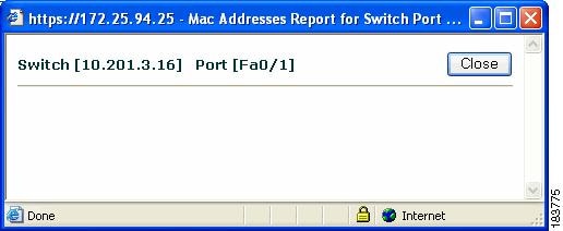
Clicking this button brings up a dialog with the MAC address of the client attached to this port, the IP address of the switch, and the Name of the port to which the client is connected. For a managed port, only one MAC address displays for the attached client device. For unmanaged ports, this dialog displays all the MAC addresses associated with this port, but will not indicate where the MAC addresses are located (could be on other switches).
Note
•
To control a port from the CAM, select a managed port profile from the dropdown menu, then click Update and Setup. Apply managed port profiles to ports on which clients are attached in order to get and set the SNMP traps from those ports. Profiles can also be applied to trunk ports. All other ports should be unmanaged. Port Profiles must already be configured under OOB Management > Profiles > Port > New (see Configure Port Profiles). There are always two default dropdown options: uncontrolled, and Default []. All ports are initially assigned the Default[uncontrolled] Port Profile. You can change the Default [] Port Profile assignment from the OOB Management > Devices > Config tab.
Note
•
This field allows you enter an optional description for ports you configure. Clicking Update saves the note for the port on the CAM.
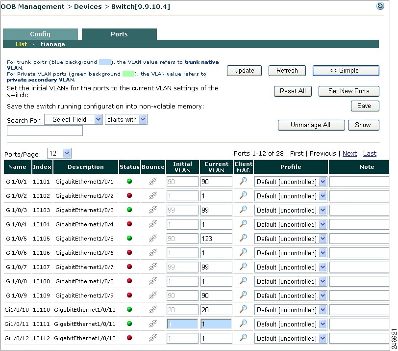
Manage Individual Ports (Linkup/Linkdown)
If the switch does not support MAC change notification/MAC move notification traps, the Mac Notif. column and Setup button are not displayed on this page (Figure 3-35). In this case, linkup/linkdown traps must be supported and configured on the switch and Clean Access Manager.
See Advanced for additional information on the use of linkup/linkdown traps.
Figure 3-35 Ports Tab—Linkup/Linkdown
Assign a Port Profile to Multiple Ports Simultaneously
If your switch configuration includes many access ports that all feature the same port profile assignments to provide remote users authentication and access to the network, you can use the OOB Management > Devices > Switch [x.x.x.x] > Ports > Manage page to assign the same port profile to many switch ports all at the same time. If you have only a couple or few ports to which you must assign port profiles, see the procedure in Manage Individual Ports (MAC Notification).
Step 1
Figure 3-36 OOB Management > Devices > Switch [x.x.x.x] > Ports > Manage
Step 2
Step 3
Step 4
Step 5
Step 6
Config Tab
The Config tab allows you to modify Basic, Advanced, and Group profile settings for a particular switch:
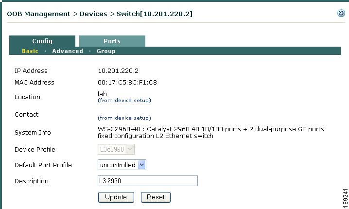
Basic
The Basic tab (Figure 3-37) shows the following values configured for the switch.
Figure 3-37 Basic Config
•
–
–
–
–
–
•
•
Note
•
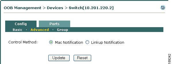
Advanced
Use the Advanced Config page (Figure 3-38) to view or configure which SNMP trap notification type the CAM SNMP Receiver will use for a particular switch.
•
Note
•
•
Figure 3-38 Advanced Config
Linkup/linkdown is a global system setting on the switch that tracks whether a connection has non-operating or operating status. With the linkup/linkdown trap method, the Clean Access Manager must poll each port to determine the number of MAC addresses on the port.
Linkdown Traps
A client machine shutdown or reboot triggers a linkdown trap sent from the switch to the CAM (if linkdown traps are set up on the switch and configured on the CAM via the Port profile). Thereafter, the client port behavior depends on the Port profile settings for that specific port.
Whether the SNMP receiver is configured for MAC notification or linkup, the CAM uses the linkdown trap to remove users. For example, the linkdown trap is used if:
•
•
Port Security
Port Security is a switch feature that restricts input to an interface by limiting and identifying MAC addresses of the stations allowed to access the port.
When you change the SNMP control method from Mac Notification to Linkup Notification, as described in Enabling Port Security, the Port Security checkbox will appear on the Advanced page (Figure 3-39) if the switch supports the feature. When using linkup notification, the Port Security feature can provide additional security by causing the port to only allow one MAC address when a user authenticates. So even if the port is connected to a hub, only the first MAC that is authenticated is allowed to send traffic. Note that availability of the Port Security feature is dependent on the switch model and OS being used.
When you enable Port Security on the CAM, the switch configuration is not immediately changed. Instead, when the next client connects to that port, the switch will add the configuration for the port which turns on Port Security for that MAC address. The switch will add that MAC address as the only MAC address allowed to connect to that port if other connection attempts are made.
Enabling Port Security
Step 1
Step 2
Step 3
Step 4
Step 5
Step 6
•
snmp-server enable traps mac-notification" line is removed from the switch configuration.•
snmp-server enable traps mac-notification" line is not removed from the switch configuration. This option can save some time if the administrator is planning to change the port back later to MAC Notification control. See Re-Enabling MAC Notification for details.)Figure 3-39 Enabling Port Security from the CAM
Note
•
•
Re-Enabling MAC Notification
Step 1
Step 2
Step 3
Step 4
Step 5
•
•
Figure 3-40 Reverting to MAC Notification from the CAM
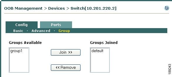
Group
This page displays all the Group Profiles configured in the Clean Access Manager, and the Group Profiles to which the switch currently belongs. You can add the switch to other Groups, or you can remove the switch from a Group Joined. To change the Group membership for all switches, go to OOB Management > Profiles > Group (see Configure Group Profiles).
Figure 3-41 Config Group
Configure Access to Authentication VLAN Change Detection
Caution
For In-Band clients and Out-of-Band clients which are still assigned to the Authentication VLAN, the Agent uses SWISS discovery packets to verify connectivity with the CAS. Once a client machine is on the Out-of-Band network and no longer communicates directly with the CAS, additional configuration is required for the client to determine whether it is still on the Access VLAN or moved to the Authentication VLAN. Versions prior to the 4.1.3.0 Agent cannot identify that the client port has switched from the Access VLAN to the Authentication VLAN and require the client machine's DHCP lease to run out in order to force the Agent to perform a DHCP release/renew to get a new IP address assignment.
To ensure OOB users are able to maintain network connection when the Cisco NAC Appliance administrator is forced to "kick" users out (and move the session back to the Authentication VLAN), you can configure the Cisco NAC Appliance system to have the Agent renew the IP address via DHCP release/renew.
This VLAN change detection behavior applies to the following scenarios:
•
•
•
If the Agent detects a change, the client machine automatically refreshes its IP address via DHCP release/renew. By default, the Agent automatically polls for the VLAN assignment on the switch every 5 seconds. If you want to increase or decrease that interval, users can adjust the "VlanDetectInterval" client setting.
For OOB deployments that require a client IP change, when the user is logged out and the client port changes from the Access VLAN to the Authentication VLAN, the IP address for the client machine also needs to change to come from the Authentication VLAN. In OOB, when the user is in the Access VLAN, the Agent no longer communicates with the CAM or CAS, so the Agent is not aware when the CAM changes the VLAN for the client port. Although the CAM can bounce the port to change the IP address on the client, this solution is not recommended for IP Phone environments, as it can disrupt voice services.
To enable and specify settings to support Access to Authentication VLAN Change Detection on a Windows client with the Cisco NAC Agent installed:
Step 1
Note
Step 2
Note
Note
Out-of-Band Users
OOB User Sessions
The following triggers detect when an OOB user has logged off and will force revalidation:
•
•
Note
•
•
•
For additional details, see also Interpreting Event Logs and Manage Certified Devices.
Wired and Wireless User List Summary
Table 3-4 describes the lists used to track wired and wireless users.
Table 3-4 Wired and Wireless User List Summary
In-Band Online Users
•
•
•
Certified Devices List
•
•
•
–
–
Wired Clients and Wireless Clients
•
•
•
•
Note
Out-of-Band Online Users
•
•
Note
•
Note
•
1.
2.
3.
4.
5.
OOB Troubleshooting
•
•
•
OOB Switch Trunk Ports After Upgrade
Because Cisco NAC Appliance can control switch trunk ports for OOB (starting from release 3.6(1) and above), uplink ports for managed switches need configured as "uncontrolled" ports either before or after upgrade (see "Settings That May Change With Upgrade" in the corresponding Release Notes for Cisco NAC Appliance.
This can be done in one of two ways:
•
•
This will prevent unnecessary issues when the Default Port Profile for the switch has been configured as a managed/controlled port profile
If for some reason the above steps are omitted and the switch becomes disconnected, use the following procedure:
Step 1
Step 2
(config-if)# switchport trunk native vlan xxx(config-if)# no snmp trap mac-notification addedStep 3
Step 4
Step 5
Initialize the switch ports (under OOB Management > Devices > Devices [x.x.x.x] > Ports).
OOB Error: connected device <client_MAC> not found
Client connection errors can result from incorrect configuration of the switch profile. If attempting to log into the network using the Agent, and the Agent provides the following error: "Login Failed! OOB Error: connected device <client_MAC> not found. Please contact your network administration."
•
For example, if the switch is a 3750, but you specified it a 2950 switch profile when adding the switch, when the CAM receives the SNMP linkup trap from the switch for the client that is connecting (with the MAC address specified in the Agent error message), the CAM will attempt to contact that switch to find that MAC address. If the wrong profile is specified for the switch, or the switch is not yet configured in the CAM, the CAM will not be able to contact that switch. Changing the switch profile to 3750 will resolve this issue.
Troubleshooting SNMP
This section describes how to troubleshoot the common errors that occur in SNMP operations.
Message Not Within Time Window
Device IP Not Reachable
Error: The device IP is not reachable. Please check the device IP and try again.
This error may occur while adding a switch to CAM. This happens when the switch IP is not reachable from CAM. Check the network connectivity between the CAM and the switch.
Fetching SysObjectID
Error fetching the sysobjectid of the device <switch-ip-address>. Please check the SNMP settings on the device. They should match the SNMP settings defined in the device profile.
This happens when the SNMP read settings on the device do not match with the settings configured in the CAM under OOB Management > Profiles > Device.
SNMP Request Timed Out
Error: SNMP request timed out [1.3.6.1.4.1.9.9.215.1.1.5.0]
CAM logs contain the error as shown in the following example:
2012-01-08 18:41:57.010 +0530 [TP-Processor23] ERROR com.perfigo.wlan.web.sms.Switch
- switch [9.0.20.3] SNMP WRITE failed, 1 consecutive write failures!
2012-01-08 18:41:57.011 +0530 [TP-Processor23] ERROR com.perfigo.wlan.web.sms.SnmpManagerThis error happens when there is a mismatch in the SNMP Write settings. When the admin clicks the ports for a switch, then this error is displayed in the CAM web console.
The SNMP Write settings setup in the device profile under OOB Management > Profiles > Device are different from the settings in the switch configuration. Make sure the settings are the same.
Unknown User Name
Error: SNMP failure [1.3.6.1.4.1.9.9.215.1.1.5.0]: Unknown user name
This error occurs when the SNMP V3 username mentioned in the device profile under OOB Management > Profiles > Device does not exist in the switch configuration.
Wrong Digest
Error: SNMP failure [1.3.6.1.4.1.9.9.215.1.1.5.0]: Wrong digest
This error occurs when the SNMP V3 Auth password or Auth type mentioned in the device profile under OOB Management > Profiles > Device does not match with the one in the switch configuration.
Authorization Error
Error: SNMP failure [1.3.6.1.4.1.9.9.215.1.1.5.0]: Authorization error
This error occurs when the SNMP V3 Auth/Priv is not setup in the device profile under OOB Management > Profiles > Device, while the username in the switch configuration has been setup with the Auth/Priv security level.
Unsupported Security Level
Error: SNMP failure [1.3.6.1.4.1.9.9.215.1.1.5.0]: Unsupported Security Level
This error occurs when the SNMP V3 Auth/Priv is setup in the device profile under OOB Management > Profiles > Device, while the username in the switch configuration is not using any Auth/Priv security level.
No Access
Error: SNMP failure [1.3.6.1.4.1.9.9.215.1.1.5.0]: No access
This occurs when SNMP V3 user is not properly configured.
While creating a SNMP V3 user on the switch, the commands must be executed in the right order. The following order is recommended:
1.
2.
3.
If there is a change in the above order, then the user is not properly bound to the correct Group or View. This causes issues to the user and throws the above error.
OOB Client MAC/IP Not Found
Invalid Switch Configuration-OOB Error: OOB Client MAC/IP not found. Please contact network administrator.
This error usually occurs when the user tries to login. This happens when CAM is not able to find a matching entry for the client's MAC address in the Discovered Clients list
Perform the following steps:
•
•
After performing the above, the user will be able to login successfully.
Message Not Within Time Window
Error: Message not within time window
This error is seen in packet captures performed at CAM when SNMP V3 is used for write operations. CAM stores the snmpEngineID, snmpEngineBoots and snmpEngineTime for every switch in its memory. When a switch is re-configured then the engineBoots and engineTime are reset. When the switch sends request, then these values are matched with the values that are stored in CAM for that engineID. If they are different, then the error message "Message not within time window" is displayed.
Workaround:
Update the switch profile. Go to the device profile under OOB Management > Profiles > Device for the corresponding switch and update it. This would allow the CAM to reset the engineBoots and engineTime for the switches to default values. Another workaround is to restart the CAM perfigo service.
Note
Additional Information
In the CAM web console, navigate to OOB Management > Profiles > Port > New. When the option Generate event logs when there are multiple MAC addresses detected on the same switch port is enabled, there may be an impact on performance, as hub detection happens for every SNMP trap. Make sure this option is disabled when using switches with large number of ports like 6500.