Table Of Contents
Modular Services Card Overview
Overview of Modular Services Cards and Physical Layer Interface Modules
PLIM Physical Interface Module On Ingress
PLIM Physical Interface Section On Egress
Physical Layer Interface Modules
OC-768 Packet-Over-SONET (POS) PLIMs
OC-192 Packet-Over-SONET/Dynamic Packet Transport PLIMs
OC-48 Packet Over SONET/Dynamic Packet Transport PLIMs
Oversubscription of 10-GE Ports
Modular Services Card Overview
This chapter describes the modular services card (MSC) and associated physical layer interface modules (PLIMs) of the Cisco CRS-1 Carrier Routing System. It includes the following sections:
•
Overview of Modular Services Cards and Physical Layer Interface Modules
•
Overview of Modular Services Cards and Physical Layer Interface Modules
The modular services card (MSC) is the Layer 3 forwarding engine in the CRS-1 routing system. Each MSC is paired with a corresponding physical layer interface module (PLIM) that contains the packet interfaces for the MSC. An MSC can be paired with different types of PLIMs to provide a variety of packet interfaces, such as OC-192 POS and OC-48 POS.
Each MSC and associated PLIM implement Layer 1 through Layer 3 functionality of the OSI model that consists of physical layer framers and optics, MAC framing and access control, and packet lookup and forwarding capability. The MSCs deliver line-rate performance at line rate.
The MSCs support this type of traffic (IPv4, IPv6) while the route processor (RP) implements BGP routing, OSPF IS-IS, and distributes routing table information, whereas the MSC forwards data packets.
MSCs and PLIMs are installed on opposite sides of the line card chassis, and mate through the line card chassis midplane. Each MSC/PLIM pair is installed in corresponding chassis slots in the chassis (on opposite sides of the chassis).
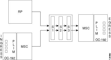
Figure 5-1 shows how data enters the optical interfaces on the ingress PLIM and is passed to the ingress MSC. From there, data packets are converted to cells, and forwarded to the switch fabric, where the data cells are switched to the egress MSC and are reassembled into data packets and forwarded out the egress PLIM.
Figure 5-1 MSCs, PLIMs, and Switch Fabric Diagram
The PLIM provides the interface to user IP data. PLIMs perform Layer 1 and Layer 2 functions, such as framing, clock recovery, serialization and deserialization, channelization, and optical interfacing. Different PLIMs provide a range of optical interfaces, such as very-short-reach (VSR), intermediate-reach (IR), or long-reach (LR).
The MSC receives the data from the PLIM and then, based upon the IP packet header, it will perform QoS functionality or other actions, such as the mapping of VLANs. And for ingress data, it will disassemble the packet into 36-byte fabric cells.
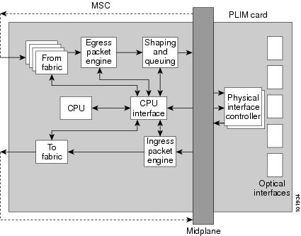
Figure 5-2 is a simple block diagram of the major components of an MSC/PLIM pair. These components are described in the following sections:
•
•
•
Figure 5-2 MSC and PLIM Simple Block Diagram
PLIM Physical Interface Module On Ingress
As shown in Figure 5-2, received data enters a PLIM from the physical optical interface. The data is routed to the physical interface controller, which provides the interface between the physical ports, and the Layer 3 function of the MSC. For receive (ingress) data, the physical interface controller performs the following functions:
•
•
•
–
–
MSC Ingress Packet Engine
The ingress packet engine performs packet processing on the received data. It makes the forwarding decision and places the data into a rate-shaping queue in the "to fabric" section of the board. To perform Layer 3 forwarding, the packet engine performs the following functions:
•
•
•
•
•
•
MSC To Fabric Section Queuing
The "to fabric" section of the board takes packets from the ingress packet engine, segments them into fabric cells, and distributes (sprays) the cells into the eight planes of the switch fabric. Because each MSC has multiple connections per plane, the "to fabric" section distributes the cells over the links within a fabric plane. The chassis midplane provides the path between the "to fabric" section and the switch fabric (as shown in Figure 5-1 and Figure 5-2).
MSC From Fabric Section
The "from fabric" section of the board receives cells from the switch fabric and reassembles the cells into IP packets. The section then places the IP packets in one of its 8K egress queues, which helps the section adjust for the speed variations between the switch fabric and the egress packet engine.
MSC Egress Packet Engine
The transmit (egress) packet engine performs a lookup on the IP address or MPLS label of the egress packet. The egress packet engine performs transmit side features such as output committed access rate (CAR), access lists, diffServ policing, MAC layer encapsulation, and so on.
Shaping and Queuing Function
The transmit packet engine sends the egress packet to the shaping and queuing function (shape and regulate queues function), which contains the output queues. Here the queues are mapped to ports and classes of service (CoS) within a port. Random early-detection algorithms perform active queue management to maintain low average queue occupancies and delays.
PLIM Physical Interface Section On Egress
On the transmit (egress) path, the physical interface controller provides the interface between the MSC and the physical ports on the PLIM. For the egress path, the controller performs the following functions:
•
•
•
•
•
MSC CPU and CPU Interface
As shown in Figure 5-2, the MSC contains a central processing unit (CPU) that performs the following functions:
•
•
•
The CPU subsystem includes:
•
•
•
•
•
•
The CPU interface module, provides the interface between the CPU subsystem and the other ASICs on the MSC and PLIM.
The MSC also contains a service processor (SP) module that provides:
•
•
•
•
The SP, CPU subsystem, and CPU interface work together to perform housekeeping, communication, and control plane functions for the MSC. The SP controls card power up, environmental monitoring, and Ethernet communication with the line card chassis RP cards. The CPU subsystem performs a number of control plane functions, including receipt of FIB downloads, local PLU and TLU management, statistics gathering and performance monitoring, and MSC ASIC management and fault-handling. The CPU interface drives high-speed communication ports to all ASICs on the MSC and PLIM. The CPU talks to the CPU interface through a high-speed bus attached to its memory controller.
Modular Services Card
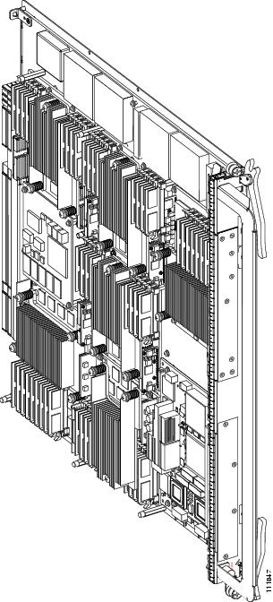
Figure 5-3 shows a Cisco CRS-1 Carrier Routing System Modular Services Card (MSC). An MSC fits into any available MSC slot and connects directly to the midplane.
Figure 5-3 Modular Services Card, Original Version (CRS-MSC)
Note
Figure 5-4 and Figure 5-5 show front panels of two MSC versions.
Figure 5-4 CRS-MSC Front Panel
The MSC front panel contains:
•
•
Figure 5-5 CRS-MSC-B Front Panel
Physical Layer Interface Modules
A physical layer interface module (PLIM) provides the packet interfaces for the routing system. Optic modules on the PLIM contain ports to which fiber-optic cables are connected. User data is received and transmitted through the PLIM ports, and converted between the optical signals (used in the network) and the electrical signals (used by Cisco CRS-1 components).
Each PLIM is paired with a modular services card (MSC) through the chassis midplane. The MSC provides Layer 3 services for the user data, and the PLIM provides Layer 1 and Layer 2 services. An MSC can be paired with different types of PLIMs to provide a variety of packet interfaces and port densities (for example, OC-192 and 10-Gigabit Ethernet).
MSCs and PLIMs are installed on opposite sides of the line card chassis, and mate through the chassis midplane. Each MSC and PLIM pair is installed in corresponding chassis slots in the chassis (on opposite sides of the chassis). The chassis midplane enables you to remove and replace an MSC without disconnecting the user cables on the PLIM. Physical layer interface modules (PLIMs) contain the packet interfaces for the routing system.
The use of separate PLIMs also provides the ability to choose a number of different packet interfaces and port densities. Table 5-1 lists the orderable PLIM modules
The following sections describe the types of PLIMs currently available for the Cisco CRS-1:
•
•
•
•
Warning
Warning
OC-768 Packet-Over-SONET (POS) PLIMs
The 1-port OC-768 PLIM provides an interface of 40 gigabits per second (Gbps), which is the OC-768 line rate. The PLIM performs Layer 1 and Layer 2 processing for an OC-768 data stream by removing and adding the proper header information as data packets enter and exit the PLIM.
The OC-768 PLIM is a class 1 laser product that operates in POS mode only; DPT mode is not supported. The PLIM contains:
•
•
•
•
The Cisco IOS XR software also provides diagnostic functions for the PLIM.
Figure 5-6 shows the front panel of the OC-768 PLIM.
Figure 5-6 1-Port OC-768 PLIM Front Panel
The 1-port OC-768 PLIM has the following components: and physical characteristics:
•
•
–
–
–
•
Yellow or amber indicates a problem with the PLIM. If the LED is off (dark), check that the board is properly seated and that system power is on.•
•
•
•
•
•
•
OC-192 Packet-Over-SONET/Dynamic Packet Transport PLIMs
The OC-192 PLIM contains four ports that can be software configured to operate in packet-over-SONET (POS) or Dynamic Packet Transport (DPT) modes. The OC-192 PLIM provides Layer 1 and Layer 2 interface capabilities for four OC-192 data steams by removing and adding the proper Layer 1 and Layer 2 header information as data packets enter and exit the PLIM. The OC-192 PLIM feeds the MSC with one 40-Gbps data packet stream.
Note
The OC-192PLIM has features described in Table 5-2.
:
The Cisco IOS XR software also provides loopback and diagnostic functions for the OC-192 PLIM.
The four different types of optics modules predicate the four major variants of the OC-192 PLIM:
•
•
•
•
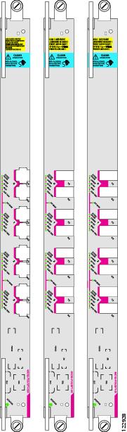
Figure 5-7 shows the front panel of the three versions of the OC-192 PLIM.
Figure 5-7 4-Port OC-192 POS/DPT VSR, SR, and IR Front Panels
Each 4-port OC-192 PLIM has the following components and physical characteristics:
•
•
•
–
–
–
–
–
•
•
•
•
•
•
OC-48 Packet Over SONET/Dynamic Packet Transport PLIMs
The OC-48 PLIM comes in three different variants which can be software configured to operate in packet-over-SONET (POS) or Dynamic Packet Transport (DPT) mode. The 16xOC-48 PLIM contains 16 OC-192 interfaces and provides Layer 1 and Layer 2 interface capabilities, for 16 separate OC-48 data streams, by removing and adding the proper Layer 1 and Layer 2 header information as data packets enter and exit the PLIM. The 16xOC-48 PLIM feeds the MSC with one 40 Gbps data packet stream.
Table 5-3 describes the features of the 16xOC-48 PLIM.
:
The Cisco IOS XR software also provides loopback and diagnostic functions for the 16xOC-48 PLIM.
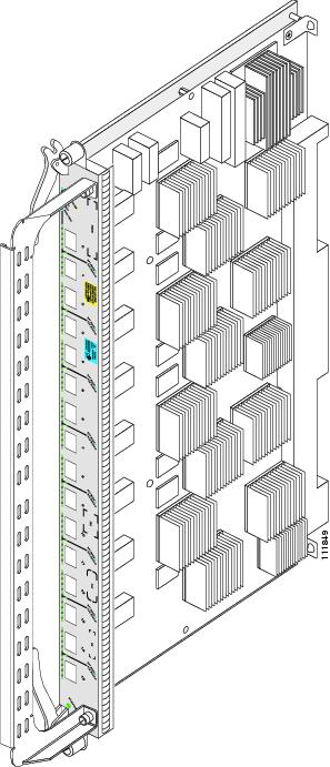
Figure 5-8 shows a 16xOC-48 PLIM.
Figure 5-8 16xOC-48 POS PLIM
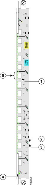
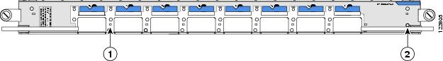
Figure 5-9 shows the front panel of a 16xOC-48 POS PLIM.
Figure 5-9 16xOC-48 POS PLIM Front Panel View
As shown in Figure 5-9, each 16xOC-48 PLIM has the following components and physical characteristics:
•
•
•
•
–
–
–
–
–
•
•
•
•
•
10-Gigabit Ethernet PLIM
The 8-port 10-Gigabit Ethernet (GE) PLIM provides from one to eight 10-GE interfaces. The PLIM supports from one to eight pluggable XENPAK optic modules that provide the 10-GE interfaces for the card. The PLIM performs Layer 1 and Layer 2 processing for up to eight 10-GE data streams by removing and adding the proper header information as data packets enter and exit the PLIM.
Although the PLIM can terminate up to 80 Gbps of traffic, the MSC forwards traffic at 40 Gbps. Therefore, the PLIM provides 40 Gbps of throughput, which it passes to the MSC as two 20-Gbps data packet streams:
•
•
Oversubscription of 10-GE Ports
If more than two optic modules are installed in either set of ports, oversubscription occurs on all ports in that set. For example, if modules are installed in ports 0 and 1, each interface has 10 Gbps of throughput. Adding another module in port 2 causes oversubscription on all of the interfaces (0, 1, and 2).
Note
10-GE PLIM Components
The 8-port 10-GE PLIM consists of:
•
•
•
Figure 5-10 shows the front panel of the 10-GE PLIM.
Figure 5-10 10-GE PLIM Front Panel
The 8-port 10-GE PLIM has the following components and physical characteristics:
•
•
•
•
•
•
•
•
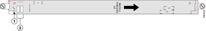
PLIM Impedance Carrier
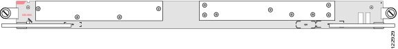
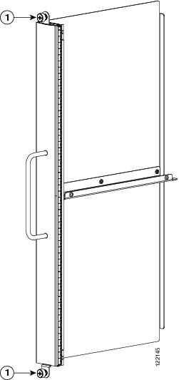
A PLIM impedance carrier must be installed in each empty PLIM slot in the Cisco CRS-1 chassis (see Figure 5-11). The CRS-1 8-slot chassis is shipped with impedance carriers installed in the empty slots. The impedance carrier preserves the integrity of the chassis and is required for EMI compliance and proper cooling in the chassis.
Figure 5-11 PLIM Impedance Carrier