Table Of Contents
Cisco IOS XR Software Overview
Control Plane and Data Plane Overview
System Discovery and Inventory
Online Insertion and Removal (OIR) Detection
RP Active and Standby Arbitration
System Controller (SC) Function
Physical Layer Interface Module (PLIM)
Overview
This chapter provides an overview of the Cisco CRS-1 8-slot line card chassis and the basic system configuration. It contains the following sections:
•
Control Plane and Data Plane Overview
System Description
The Cisco CRS-1 8-slot line card chassis is a highly scalable routing platform designed for efficient service provider point of presence (POP) evolution as the IP network grows into a multiservice network. In the initial release, the Cisco CRS-1 8-slot line card chassis consists of a single line card chassis, called the Cisco CRS-1 8-slot line card chassis.
The Cisco CRS-1 8-slot line card chassis is a mechanical enclosure that houses modular services cards (MSCs) and their associated physical layer interface modules (PLIMs), switch fabric cards (SFCs), and route processor (RP) cards. The chassis is bolted to the facility floor in an external rack. The chassis also contains its own power and cooling systems.
Note
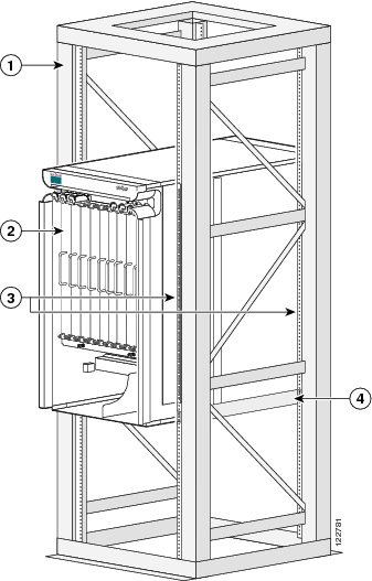
Figure 1-1 illustrates a single-chassis Cisco CRS-1 8-slot line card chassis mounted in a 4-post rack.
Figure 1-1 Cisco CRS-1 8-slot line card chassis (Single Chassis Installation)
Safety Precautions
Refer to the Regulatory Compliance and Safety Information for the Cisco CRS-1 Carrier Routing System for safety and compliance information as well as translations of warnings used in hardware documentation for the Cisco CRS-1 8-slot line card chassis.
Be careful when installing cards that have optical connectors.
Warning
Cisco IOS XR Software Overview
The operating system software for Cisco CRS-1 Carrier Routing Systems is Cisco IOS XR. The Cisco IOS XR software is designed for maximum flexibility and scalability. It is installed and activated as modular packages, allowing specific features to be installed, upgraded, or downgraded without impacting other unrelated processes. In addition, the software can be applied to all supported card types, specific card types, or specific cards.
The Cisco IOS XR software can be configured using the command line interface (CLI) or the Craft Works Interface (CWI). The CLI provides a command line environment familiar to most users of Cisco IOS software, and the CWI provides a graphical user interface in a web-based desktop application.
Command Line Interface (CLI)
The Cisco IOS XR command line interface (CLI) is available for configuring, monitoring, and maintaining the Cisco CRS-1. This user interface allows you to execute Cisco IOS XR commands through a terminal connected directly to the RP console port or over a network connection through a modem (see Figure 6-2).
Craft Works Interface (CWI)
The Cisco CRS-1 Craft Works Interface (CWI) is a client-side, web-based graphical user interface (GUI) used to configure and manage the Cisco CRS-1. The CWI is a web-based desktop application used to launch management and configuration applications. The management and configuration features include fault, configuration, performance, security, inventory, and software installation, with an emphasis on speed and efficiency. A Cisco CRS-1 can consist of a large hierarchy of shelves, cards, and ports. The CWI provides graphical representations of the physical objects in a routing system, simplifying the process of configuring and managing the routing system.
XML API
The Cisco Extensible Markup Language Applications Programming Interface (XML API) is an interface that can be used for rapidly developing client applications and Perl scripts to manage and monitor the Cisco CRS-1. These client applications can be used to configure the router or to request status information from the router. Requests are encoded in XML API tags and sent to the router. The router processes the request and sends the response to the client, by again encoding the response in XML API tags. The XML API supports readily available transport layers, including Telnet, SSH, and CORBA, and Secure Socket Later (SSL) transport.
Until now, customers used a variety of vendor-specific CLI-based scripts to manage their routers, because there was no alternative programmatic mechanism available. In addition, there has not been a common framework for developing CLI-based scripts available. In response to this need, the programmable Cisco XML API provides a common framework for rapidly developing, deploying, and maintaining the management of the Cisco CRS-1.
Use the XML API to write client applications that interact with the XML infrastructure on the Cisco CRS-1, or use the CRS-1 Management XML API to build custom end-user interfaces for configuration and information retrieval and display.
Architecture
Every Cisco CRS-1 8-slot line card chassis has 8 MSC slots, each with a capacity of 40 gigabits per second (Gbps) for a total routing capacity for each chassis of 640 Gbps or 64 terabits per second. (A terabit is 1 x 1012 bits or 1000 gigabits.) The routing system is built around a scalable, distributed three-stage Benes switch fabric and a variety of data interfaces.
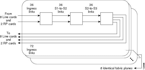
The data interfaces are contained on PLIMs that mate with an associated MSC through the chassis midplane. The switch fabric cross-connects MSCs to each other. Figure 1-2 is a simple diagram of the basic Cisco CRS-1 8-slot line card chassis architecture.
Figure 1-2 Simple Schematic of Cisco CRS-1 8-slot line card chassis Architecture
Figure 1-2 illustrates the following concepts, which are common to all Cisco CRS-1s:
•
•
•
Main Features
The main features of all Cisco CRS-1 routing systems include:
•
•
•
•
•
The Cisco CRS-1 8-slot line card chassis uses the same line cards, the same software, and the same type of midplane and switch mechanism as the Cisco CRS-1 16-Slot Line Card Chassis. It provides the higher speed interfaces found in the Cisco CRS-1 16-Slot Line Card Chassis, but in a smaller platform, allowing easier deployment in locations where power, cooling, and other facilities might be hard to provision.
Line Card Chassis Overview
The Cisco CRS-1 8-slot line card chassis is the mechanical enclosure that contains the system components. The chassis is installed in an external rack that is bolted to the facility floor, and has locking front doors and optional rear doors. The word chassis refers to either the mechanical enclosure that houses the routing system components, or to a fully loaded chassis operating as a routing system.
This section contains the following subsections:
Components
This section lists the main components of a line card chassis. It primarily identifies the components that are considered field-replaceable units (FRUs), but where additional detail is useful identifies subassemblies that are not field-replaceable.
The PLIM side of the chassis is considered the front of the chassis—this is where user data cables attach to the PLIMs and where cool air enters the chassis. Figure 1-3 shows the line card chassis from the front (PLIM) side.
Figure 1-3 Front View (PLIM Side) of the Cisco CRS-1 8-slot line card chassis
Cable management bracket
Air filter
Chassis vertical mounting brackets
Power modules
PLIM and RP slots (RP cards in middle 2 slots)
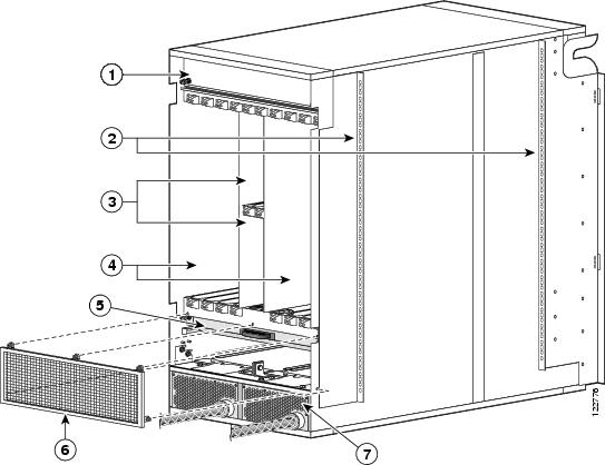
The MSC side of the chassis is considered the rear of the chassis—this is where warm air is exhausted. Figure 1-4 shows the line card chassis from the rear (MSC) side.
Figure 1-4 Rear View (MSC Side) of the Cisco CRS-1 8-slot line card chassis
Upper fan tray (beneath cover)
MSC slots
Chassis vertical mounting brackets
Lower fan tray
Switch fabric card (half-height) slots
Power distribution units (PDUs)
The line card chassis contains up to eight modular services cards (MSCs, also called line cards) and eight physical layer interface modules (PLIMs). The MSC and PLIM are an associated pair of cards that mate through the chassis midplane. The MSC provides the forwarding engine for Layer 3 routing of user data, and the PLIM provides the physical interface and connectors for the user data.
The MSC can be associated with several different PLIMs, which provide different interface speeds and technologies. The available PLIMs are:
•
•
•
•
In addition, the Cisco CRS-1 8-slot line card chassis contains:
•
•
•
•
•
See Appendix A, "CRS-1 8-Slot Line Card Chassis Specifications," for specifications about the Cisco CRS-1 8-slot line card chassis and its components.
Slot Numbers
This section identifies the location and slot numbers for the cards and modules that plug into the chassis and are considered field-replaceable units.
Figure 1-5 shows the slot numbering on the front (PLIM side) of the line card chassis.
Figure 1-5 Line Card Chassis Slot Numbers—Front (PLIM) View
The slot numbers on the PLIM side of the chassis include:
•
•
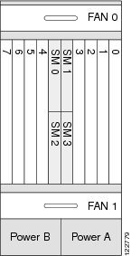
Figure 1-6 shows the slot numbering on the rear (MSC side) of the line card chassis.
Figure 1-6 Line Card Chassis Slot Numbers—Rear (MSC) View
The slot numbers on the MSC side of the chassis include:
•
•
The MSC (rear) slot numbers are reversed from the PLIM (front) slot numbers. Therefore the MSC in slot 0 and PLIM in slot 0 mate with one another through the midplane, and so do all the other MSC and PLIM slots (0 through 7).
Cable Management
The Cisco CRS-1 8-slot line card chassis arrives with a pre-installed horizontal cable-management bracket on the front of the chassis. In a single-chassis system, the following ports are for external cable connections:
•
•
•
•
The cable-management bracket is for organizing these interface cables to keep the front of the chassis clear and to eliminate sharp bends in the cables.
Caution
The cable-management bracket has a special telescoping feature that allows the bracket to be extended when the chassis is upgraded with higher-density cards. This extension feature also helps in installing the cables in the chassis.
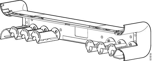
Figure 1-7 shows the chassis cable-management bracket.
Figure 1-7 Cable Management Bracket (Front of Chassis Only)
Note
Exterior Components
The line card chassis also includes (optional) front and rear locking doors, bezels, and side panels. The rear doors are optional in the stand-alone system. The cosmetic components are shipped in a separate package and must be installed on the Cisco CRS-1 8-slot line card chassis during system installation.
Control Plane and Data Plane Overview
The control plane is a logical communication path between cards, modules, and components in the chassis, tying physical components and software functions into a unified entity. The control plane is used during system discovery, inventory, configuration, booting, management, upgrades, fault detection and recovery, and performance monitoring.
The data plane is the path that packets take through the routing system from the physical layer interface module (PLIM) to a modular services card (MSC) to the switch fabric to another MSC and out a PLIM. The control plane and data plane may share some physical components. For instance, the control plane uses the switch fabric for some types of intrasystem communication, just as the data plane uses it to switch packets.
System Discovery and Inventory
The control plane hardware provides for system discovery and inventory. This process includes mechanisms to determine system topology of the control plane and switch fabric before the system has been configured.
In addition to topology discovery, the control plane hardware must also provide mechanisms for card- or module-presence detection and tracking information, such as the card type, revision, and serial number. These mechanisms allow system management software to build a database representing the CRS-1 routing system, including individual board identification and location information. A running routing system can be upgraded or serviced at any time during operation. The control plane hardware provides online insertion and removal (OIR) detection.
High Availability
The CRS-1 routing system hardware detects, isolates, and recovers from a broad range of faults, and provides failover mechanisms to redundant hardware. The control plane is a central element in achieving high availability, as it must isolate failures and direct failover events, both in the data plane and in the control plane.
To ease serviceability, the chassis identification displays and the critical, major, and minor alarm indicators are clearly visible. Each MSC, RP, and switch fabric card has an alphanumeric display and green OK LED to show current board status. Environmental conditions, including temperature and voltage levels, are monitored by several internal measurement points and reported to the routing system operator.
The RP cards function as the system controller in a Cisco CRS-1 8-slot line card chassis. Note that the PLIMs are connected to the control plane through their respective MSCs.
The control plane provides switched point-to-point Fast Ethernet (FE) connections between the control processors on various routing system components. This allows for control plane network messages, and some other paths for system communication. The dual RP cards and midplane FE traces provide redundant connections between all cards in the line card chassis. Most cards or modules contain a service processor (SP) module that provides the communication for that device within the control plane.
Some of the important functions and implementations of the control plane are listed in the following sections.
Online Insertion and Removal (OIR) Detection
Every MSC, RP, switch fabric card, power module, and so on provides a presence-detection signal to the system controller function on the RP cards. This dedicated hardware signal indicates the physical presence of a card in every slot. The presence-detection signal allows the Cisco IOS XR configuration software to quickly detect online insertion and removal (OIR) events, and identify cards that have been inserted but cannot communicate over the control plane.
PLIM Inventory
Every PLIM slot is probed by the master RP to get the board ID and type and other inventory information. The RP can read an identification chip on each PLIM, even if the PLIM is not powered on. The PLIM inventory chip can be accessed by the RP, whether or not an MSC is plugged into the MSC slot associated with the PLIM.
RP Active and Standby Arbitration
Both RP slots are directly connected by dedicated midplane signals to special hardware arbitration logic. During the boot process, this logic selects one of the RP cards to be the master (active) device; the other RP functions in standby mode. See the "Active and Standby Arbitration" section on page 6-4 for more information.
The control plane verifies that the arbitration logic selected only one RP as active (due to an unusual circumstance in which both RP cards might mistakenly be made active).
After hardware arbitration, software should verify single RP mastership through the control plane FE messaging. The arbitration hardware could elect two masters due to an unusual hardware fault. The control plane FE provides a redundant path so mastership can be verified absolutely.
Node Reset
Each RP has a dedicated reset line to every node in the chassis. Nodes include MSCs, RP cards, and fabric cards. The reset lines fan out from each RP and are connected to the SP on the node cards. Only the master RP can assert these reset lines; the standby RP reset lines are isolated by the RP arbitration logic. The reset lines allow the RP to force a board reset from hardware, and is used only if a board does not respond to control network messages. When this mechanism is used to reset an SP, power to all other chips on that node are turned off until the reset SP has rebooted and enabled power to the local board. To prevent glitches on the reset lines from causing inadvertent resets, as might occur during an RP OIR event, a reset from this signal can be triggered only from an encoded string of high to low transitions.
Control Plane Components
This section describes the control plane functions of various components in the routing system.
Service Processor (SP)
A Service Processor (SP) module is attached to the Modular Service Card (MSC), Route Processor (RP), switch fabric modules, and the power control and blower control systems. When a card or module is inserted into a powered-up chassis, the SP module on that card is always powered up; it cannot be powered down separately from the chassis power. Each service processor module has a Fast Ethernet (FE) connection to each SC on the RP.
System Controller (SC) Function
The System Controller (SC), which is contained on the Route Processor (RP) is the central point of control within a line card chassis. At least one SC must be operational at all times for a chassis to function as part of a routing system. Redundant SCs are provided for each chassis, so that loss or removal of any single SC does not bring down a chassis. The SC instructs individual SPs to power up nodes, provides code images for each card or module to download, and resets any node that it determines is unresponsive. The master SC is a single control-and-arbitration point in the chassis, and determines master and standby RP status when necessary.
Modular Services Card (MSC)
The Modular Service Card (MSC) is the primary data-forwarding engine. The MSC provides Layer 2 and Layer 3 packet processing and queuing. The MSC CPU performs a number of control plane functions, including forwarding information base (FIB) download receive, local PLU/TLU management, statistics gathering and performance monitoring, and ASIC management and fault handling.
Physical Layer Interface Module (PLIM)
The Physical Layer Interface Module (PLIM) contains the physical interfaces to external data circuits. The PLIM does not have its own SP module. Instead, the MSC SP module controls most of the basic control plane functions for the PLIM. These functions include reading and writing the PLIM NVRAM, which contains the board type, revision, serial number, and other information from manufacturing.
The PLIM does not have a dedicated reset signal coming directly from the RP, as the MSC itself does. When the MSC SP receives a reset, it shuts off power to the MSC and the PLIM power components. When there is no MSC present, the associated PLIM is not powered on.
Route Processor
There are two RP slots in each line card chassis. The chassis midplane connects the arbitration logic of the two RP cards so that one RP becomes the master (active) and one RP becomes the standby. The active RP distributes software images to the SP and MSC, while the standby RP monitors the active RP in case it is required to become the active card due to a failover event.
The RP is a building block of the routing system control plane processing and database solution. The RIB and FIB databases reside on one or more RP cards. Routing protocols, such as BGP and OSPF, run on the RP cards and update the route databases. These databases are downloaded to the MSCs, and the MSC forwarding engines are programmed appropriately.
HS123 Switch Fabric Cards
All switch fabric cards contain switch element chips, and in some cases parallel optical devices, and a service processor that provides a control plane interface. The hardware control plane interface communicates over Fast Ethernet links, which provide a channel for fabric configuration and maintenance. Fabric cards can be hot-swapped at any time, as the fabric has multiple planes and can operate with fewer planes at degraded performance levels. You can upgrade the CRS-1 routing system switch fabric by bringing down one plane at a time. During the fabric upgrade, some fabric planes may run in one configuration while others run in a different configuration.
In addition to configuring the fabric chips, the control plane hardware monitors the fabric for faults. Some faults require software to isolate failed chips or links. The service processor software monitors link health and executes isolation actions.
Alphanumeric Displays
Alphanumeric displays on the MSC, switch fabric card, and RP card reveal operational states. The display consists of two lines of four characters each, therefore some messages are wrapped or truncated.
Depending on whether it is the active RP or the standby RP in the system, the alphanumeric display on the route processor typically displays either:
ACTVRPor
STBYRPAll other nodes typically display:
IOS-XRAdditionally, the alphanumeric displays reveal the node states listed in Table 1-1.
Fan Trays
Fan trays are monitored by the RP and an SP module that measures airflow and controls fan RPM. As temperatures increase, the SP increases blower RPM to provide increased cooling capacity.
Line Card Chassis Midplane
The chassis midplane provides intrachassis connectivity for cards and modules in the routing system. The midplane is mostly passive, though it does contain active NVRAM components that store tracking-number and manufacturing information, and MAC addresses. Software stores the chassis ID value in the NVRAM.