-
Cisco CRS-1 Carrier Routing System 16-Slot Line Card Chassis System Description
-
Preface
-
Cisco CRS-1 Carrier Routing System
-
Chassis Power System
-
Chassis Cooling System
-
Switch Fabric
-
Modular Services Cards (MSCs) and Physical Layer Interface Modules (PLIMs)
-
Route Processor
-
Cable Management, System Interconnection, and BITS Support
-
Control Plane
-
Cisco CRS-1 Carrier Routing System 16-Slot Line Card Chassis Specifications
-
Index
-
Table Of Contents
Cisco CRS-1 Carrier Routing System
Cisco CRS-1 Routing System Overview
Cisco CRS-1 Carrier Routing System Architecture
Main Features of the Cisco CRS-1 Carrier Routing System
Line Card Chassis Slot Numbers
Line Card Chassis Cable Management
Line Card Chassis Exterior Components
Cisco CRS-1 Carrier Routing System
This chapter provides an overview of the Cisco CRS-1 Carrier Routing System and the basic system configuration. It contains the following sections:
•
Cisco CRS-1 Routing System Overview
•
•
Cisco CRS-1 Routing System Overview
The Cisco CRS-1 Carrier Routing System is a highly scalable routing platform designed for efficient service provider point of presence (POP) evolution as the IP network grows into a multiservices network.
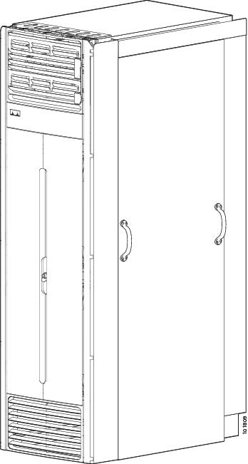
The Cisco CRS-1 16-slot line card chassis is a mechanical enclosure that contains modular services cards (MSCs) and their associated physical layer interface modules (PLIMs), switch fabric cards, and route processor (RP) cards. The chassis is bolted to the facility floor and does not require an external rack. The chassis also contains its own power and cooling systems. See the "Line Card Chassis Overview" section for more information about the chassis.
Figure 1-1 shows a Cisco CRS-1 16-slot line card chassis (with external cosmetics installed).
Figure 1-1 Cisco CRS-1 16-Slot Line Card Chassis
Cisco CRS-1 Carrier Routing System Architecture
Every Cisco CRS-1 16-slot line card chassis has 16 modular service card (MSC) slots, each with a capacity of 40 gigabits per second (Gbps) ingress and 40 Gbps egress, for a total routing capacity per chassis of 1280 Gbps or 1.2 terabits per second (Tbps). (A terabit is 1 x 1012 bits or 1000 gigabits.)
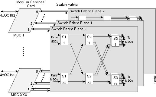
The routing system is built around a scalable, distributed three-stage Benes switch fabric and a variety of data interfaces. The data interfaces are contained on PLIMs that mate with an associated MSC through the chassis midplane. The switch fabric cross-connects MSCs to each other. Figure 1-2 is a simple diagram of the basic Cisco CRS-1 routing system architecture.
Figure 1-2 Simple Cisco CRS-1 Routing System Architecture
Figure 1-2 illustrates the following concepts, which are common to all Cisco CRS-1 routing systems:
•
•
•
Main Features of the Cisco CRS-1 Carrier Routing System
The main features of all Cisco CRS-1 routing systems include:
•
•
•
•
Line Card Chassis Overview
The Cisco CRS-1 16-slot line card chassis is the mechanical enclosure that contains the system components. The line card chassis is secured to the floor and has a locking front and optional rear doors. The line card chassis is a complete rack enclosed in a cabinet. A single-shelf (standalone) system consists of a single line card chassis only. A multishelf system consists of two line card chassis connected to a single fabric card chassis.
This section contains the following subsections:
•
•
•
Line Card Chassis Components
Following is a list of the main components of a Cisco CRS-1 16-slot line card chassis. Most of the components are field-replaceable units (FRUs), which means they can be replaced by customers in the field.
•
An MSC exists, but it can be associated with several different PLIMs, which provide different interface speeds and technologies. The available PLIMs are:
–
–
–
–
•
•
The RP also monitors system alarms and controls the system fans. LEDS on the front panel indicate active alarm conditions. See Chapter 6, "Route Processor."
•
•
•
•
•
•
The PLIM side of the chassis is considered the front of the chassis—this is where user data cables attach to the PLIMs and where cool air enters the chassis. The MSC side, which is where warm air is exhausted, is considered the rear of the chassis.
See Appendix A, "Cisco CRS-1 Carrier Routing System 16-Slot Line Card Chassis Specifications," for environmental and operating specifications for the line card chassis and its components.
The following figures show a front and rear view of a line card chassis.
Figure 1-3 Line Card Chassis Front View
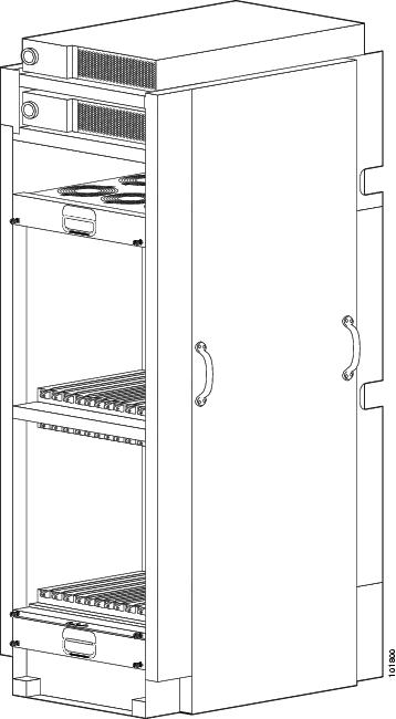
Figure 1-4 CRS-1 16-Slot Line Card Chassis Rear View
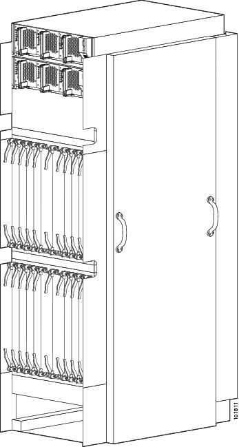
Figure 1-5 is the front view of a line card chassis with cards installed.
Figure 1-5 CRS-1 16-Slot Line Card Chassis Front View With Cards Installed
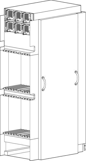
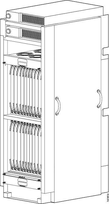
Figure 1-6 is a rear view of the line card chassis with modular services cards installed.
Figure 1-6 CRS-1 16-Slot Line Card Chassis Rear View with Modular Services Cards Installed
Line Card Chassis Slot Numbers
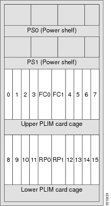
This section describes the location and slot numbers for cards and modules that plug into the chassis. Figure 1-7 shows the slot numbers on the PLIM (front) side of the line card chassis.
Figure 1-7 Cisco CRS-1 16-Slot Line Card Chassis Front View Slot Numbers (PLIM Side)
As shown, the line card chassis numbers on the PLIM side of the chassis include:
•
•
•
•
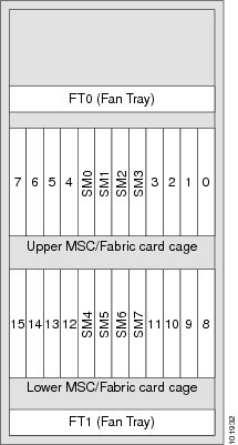
Figure 1-8 shows the slot numbers on the MSC (rear) side of the line card chassis.
Figure 1-8 Cisco CRS-1 16-Slot Line Card Chassis Rear View Slot Numbers (MSC Side)
As shown, the slot numbers on the MSC side of the chassis include:
•
•
•
•
The MSC slot numbers are reversed from the PLIM slot numbers on the other side of the chassis. Because an MSC mates with its associated PLIM through the midplane, MSC slot 0 is on the far right side of the chassis looking at it from the MSC (rear) side; PLIM slot 0 is on the far left side of the chassis looking at if from the PLIM (front) side. MSC slot 0 and PLIM slot 0 mate with one another through the midplane, and so do all the other MSC and PLIM slots (2 through 15).
Line Card Chassis Footprint
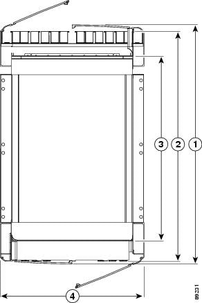
Figure 1-9 is a top view of the line card chassis footprint (with optional front and rear cosmetics installed).
Figure 1-9 Top View of CRS-1 16-Slot Line Card Chassis
40.236 in. (102.199 cm)
38.264 in. (97.191 cm)
32.766 in. (83.226 cm)
23.546 in. (59.807 cm)
The dimensions listed in the previous figure show the:
•
•
•
•
Note
Line Card Chassis Cable Management
The Cisco CRS-1 16-slot line card chassis has cable-management features for both the PLIM and MSC sides of the chassis. The PLIM side of the chassis has horizontal cable-management trays above both card cages. These trays have a special telescoping feature that allows them to be extended when the chassis is upgraded with higher-density cards. This extension feature also helps in installing the cables in the chassis.
The MSC side of the chassis has a single non-telescoping cable-management tray above the lower card cage (in the middle of the chassis). In a single-shelf system, there are no external cables connected to the MSC side of the chassis. See the Cisco CRS-1 Carrier Routing System 16-Slot Line Card Chassis Installation Guide for detailed information about chassis cabling and cable management.
Line Card Chassis Exterior Components
The Cisco CRS-1 16-slot line card chassis also includes front and rear locking doors, bezels and side panels. The rear doors are optional in the stand-alone system. The cosmetic components are shipped in a separate package and must be installed on the Cisco CRS-1 16-slot line card chassis during system installation. Figure 1-10 shows the front of the Cisco CRS-1 16-slot line card chassis exterior components.
Figure 1-10 CRS-1 16-Slot Line Card Chassis Front Exterior Components