Feedback
Table Of Contents
Setting Up Basic IP UPC Services
Network-Service Considerations
Establishing a Network-Service Definition
Perform Preconfiguration Tasks
Configure Signaling on Voice Ports
Tweak Your System Configuration
Enabling QoS Features for VoIP
Fragmentation and Interleaving
Traffic Shaping for Frame Relay
Other Bandwidth-Reduction Features
Choosing an SPE-Firmware Update or Upgrade Strategy
SPE Firmware Upgrade Scenarios
Displaying SPE Firmware Versions
Upgrading SPE Firmware from the Cisco.com TFTP Server
Downloading SPE Firmware from Cisco.com
Copying SPE Firmware from a Local TFTP Server
Upgrading SPE Firmware from Diskettes
Copying SPE Firmware to Your PC
Copying SPE Firmware from Your PC to the SPEs
Using the SPE Firmware Bundled with the Cisco IOS Software
Configuring Classic-Split Mode
Classic-Split Configuration Commands
Upgrading to a High-Availability Cisco IOS Release
Configuring Handover-Split Mode
Configuring Handover-Split Mode in Extraload
Handover-Split Configuration Commands
Managing a Handover Split with SS7
Sample Handover-Split Configuration
Provisioning
This chapter describes basic service provisioning, including IP service considerations, configuration of Voice over IP, upgrade procedures, and configuration of split modes. It contains the following sections:
•
Setting Up Basic IP UPC Services
Tip
For details on safety recommendations, site requirements (including shelf specifications, space, chassis heights, rack types, mounting options, power, and plant wiring), and site logs for monitoring installation progress or recording upgrade history, refer to the Cisco AS5850 Universal Gateway Hardware Installation Guide, available online at the Cisco AS5850 product documentation website.
Setting Up Basic IP UPC Services
This section describes how to set up and provision basic IP universal-port-card services using a Cisco AS5850 universal gateway. It is tailored for network engineers who work with dialup access technologies, and assumes that the reader is Cisco certified or familiar with Cisco IOS routers and technologies.
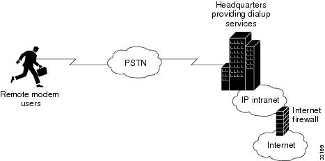
Corporate users and Internet service providers (ISPs) install dialup services to facilitate e-mail, e-commerce, and application/database access for employees, roaming sales personnel, household consumers, and students (see Figure 5-1). As a corporate user or ISP, you can do the following:
•
•
Figure 5-1 Business Scenario
Network-Service Considerations
The network-service definition for a corporate user generally differs from that for an ISP, as shown in Table 5-1.
Establishing a Network-Service Definition
Begin your implementation of basic IP UPC services by establishing a network service definition. Use the perspectives described in Table 5-1 preceding and in the following list of design and configuration considerations as a guide. A conservative approach is to project your current deployment and design into a three-month, one-year, and five-year timeline.
Step 1
•
•
•
Step 2
Step 3
•
•
Step 4
•
•
•
•
•
Step 5
•
•
•
•
•
Step 6
Step 7
•
•
•
Step 8
•
•
•
Step 9
Step 10
Step 11
•
•
Step 12
•
•
Step 13
•
•
Step 14
Step 15
Step 16
Step 17
Configuring Voice over IP
Voice over IP (VoIP) technology enables voice-capable routers and switches to transport packetized live voice traffic such as telephone calls over IP data intranetworks or internetworks rather than public switched telephone networks (PSTN) or private TDM (PBX) networks. VoIP thus enables toll bypass, remote PBX presence over WANs, unified voice and data trunking, and plain old telephone service (POTS)-Internet telephony gateways. VoIP enables more efficient and full use of your existing IP data network, reducing both transmission costs and possibly your need to support dual (voice and data) networks.
Routers and switches such as the Cisco AS5350 and Cisco AS5400 universal gateways can handle origination, transport, and termination of VoIP traffic. They digitize analog voice signals, compress them, package them into a series of discrete packets, and transport them interleaved with data packets. They can transmit VoIP packets to both VoIP and non-VoIP destinations, and can receive both VoIP and non-VoIP calls. When data lines are busy, they can spill traffic onto the PSTN.
To ensure acceptable quality of service (QoS) for your voice users, it is important that you configure your gateway carefully and monitor its performance vigilantly—to ensure, for voice traffic, priority service with minimal loss and delay. Unlike most other types of data, voice is intolerant of almost any form of loss or delay. Users cannot wait for a destination device to reorder packets and request that the sending device retransmit any that are missing, as it does for most other data types.
To configure basic VoIP, in general you need to do the following:
•
•
You might also need to do the following:
•
•
•
•
•
This section briefly introduces the subject of configuring VoIP and overviews the first few configuration tasks. It describes, at a high level, some of the voice QoS features that you can enable. Most important, it points you to other references from which you can gain a broader and deeper look at the subject.
Section contents are as follows:
•
Note
Note
VoIP Basics
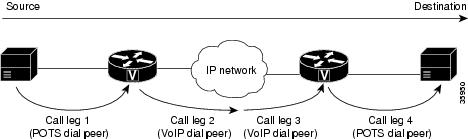
Before you configure VoIP on your gateway, you should understand at a high level what happens when you place a VoIP call. Think of each event in a call flow as occurring on one of the several "legs" of a call, as shown in the following typical scenario. Other scenarios are possible, of course, including ones where the call destination is an IP phone and the call never leaves the IP network.
•
•
•
•
Figure 5-2 Call Legs
Legs connecting a local device (typically a phone, fax machine, or PBX) to a gateway are called POTS (plain old telephone service) legs. Legs connecting a gateway to the IP network are called VoIP legs. A POTS or VoIP leg is either inbound or outbound, from the perspective of the associated gateway, as shown in Table 5-2 below.
A gateway conferences two call legs—an inbound POTS with an outbound VoIP or an inbound VoIP with an outbound POTS—to create an end-to-end call through the gateway. A call that passes through both an originating gateway and a destination gateway has four call legs.
Call Flow
Table 5-3 and Table 5-4 detail the general call flow from the perspective of an originating and destination gateway respectively.
Dial Peers
Each kind of call leg into or out of a gateway—inbound POTS, outbound VoIP, inbound VoIP, and outbound POTS—must have assigned to it a set of allowable call scenarios, called dial peers.
•
•
A dial peer is, essentially, a single static route within a routing table. A collection of dial peers constitutes a dial plan.
Syntax
A POTS dial peer has the following syntax:
dial-peer voice tag potsdestination-pattern numberport port#other configurable optionswhere tag is a numeric value of local significance only, number is the full E.164 phone number of the associated endpoint, and port# is the voice port in the gateway through which the call is transmitted once a destination pattern is matched.
A VoIP dial peer has the following syntax:
dial-peer voip tag voipdestination-pattern numbersession target data addressother configurable optionswhere tag is a numeric value of local significance only, number is the full E.164 phone number of the associated endpoint, and data address is where the gateway sends a call whose destination pattern matches the one in the peer.
Matching Rules
A gateway redirects an incoming call along the most appropriate outbound leg. It selects the most appropriate leg by first finding the POTS or VoIP (depending on call direction) dial peer whose destination pattern matches the call's dialed digits. For outbound VoIP legs, it chooses the longest matching dial peer. If more than one such match exists, it checks whether preferences have been assigned those peers and selects the peer with the lowest preference level.
Example
Let us say, for a very simple example (your implementation will be far more complex), that a company has offices in San Jose and Newark. Extensions in the San Jose office are in the range 5000 to 5999, those in the Newark office in the range 6000 to 6999. A caller at San Jose extension 5000 wants to call Newark extension 6000. The dial peers shown in Table 5-5are needed to make this connection.
When the San Jose caller at extension 5000 dials the digits 6000, the originating gateway in San Jose does the following:
1.
2.
3.
The destination gateway in Newark now does the following:
1.
2.
3.
In this west-to-east scenario, dial peers 2 and 4 are used, in that order. If Newark extension 6000 were to call San Jose extension 5000, dial peers 3 and 1 would be used, in that order.
Configuring Basic VoIP
Configuring basic VoIP involves the following:
•
•
•
Perform Preconfiguration Tasks
Before you configure your gateway for VoIP, complete the following tasks. See the earlier sections in this book and the references at the end of this section for the additional information you need to do so.
Step 1
Step 2
Step 3
Step 4
•
•
•
Step 5
Step 6
•
•
Configure Signaling on Voice Ports
Your dial feature card supports ISDN PRI, E1 R2, and T1 CAS digital signaling. Configure your voice ports according to signaling type. Set parameters as needed for input gain, output attenuation, echo cancellation, various timeouts, and translation rules. Defaults are generally adequate, but may need to be tweaked for some networks.
Note
Tip
•
http://www.cisco.com/en/US/products/sw/iosswrel/ps1835/products_configuration_guide_book09186a0080080ada.html•
http://www.cisco.com/warp/public/788/signalling/e1r2config.html
ISDN PRI Signaling
Signaling for ISDN PRI VoIP is handled by ISDN PRI group configuration. If you have ISDN PRI voice ports, be sure to complete ISDN PRI, D-channel, and NFAS configuration, as appropriate.
Ensure that multiframes are established on the serial interfaces (acting as D channel). Then set parameters as needed for input gain, output attenuation, echo cancellation, various timeouts, and translation rules.
E1 R2 Signaling
R2 is an international signaling standard for channelized E1 networks used in Europe, Asia, and South America, equivalent to channelized T1 signaling in North America. There are two elements to R2 signaling:
•
•
If you have ISDN PRI voice ports, be sure to complete E1 R2 signaling configuration. Configure signaling types and, if necessary, set parameters unique to specific countries.
T1 CAS Signaling
Channel-associated signaling (CAS) occurs in-band within the data channel, rather than on a separate signaling channel as is the case (on the D channel) with ISDN PRI. For T1 CAS, specify parameters such as frame type and line code.
Configure Dial Peers
Your next step in preparing to set up dial peers is to determine the configurable options that you want to enable.
Configurable Options
Configurable options are the attributes to be applied to calls handled using that dial peer. These typically include, at a minimum, required quality of service, codec for voice encoding, and whether voice-activity detection is to be enabled. The following attributes, for example, are typical in a VoIP dial peer:
req-qos best-effortcodec g711ulawvadYou have many options and great flexibility in configuring dial peers. Table 5-6 and Table 5-7 show the most common configurable options that you can enable in POTS and VoIP dial peers, respectively, from config or config-dial-peer mode.
Here are a few of the things that you can do with these commands in config or config-dial-peer mode:
•
Example: Use 6... to denote a 4-digit number beginning with 6.
•
Example: Use 6... to denote a 4-digit number beginning with 6; use 9t to denote a variable-length number beginning with 9.
•
Example: Prepend 9 to calls that pass through a PBX requiring 9 to access an outside line; replace prefixes that are stripped by a dial peer because they match the destination pattern.
•
Example: Expand local 5-digit extensions beginning with 7 to the full E.164 number 1-408-7xxx.
•
Example: Establish multiple dial peers, each for a different voice port, and each containing the same destination pattern; the gateway directs inbound calls to the voice ports in sequence until it reaches one that is not busy.
•
Example: Assign preference 1 to dial-peer voice 1, which directs outbound calls over the IP network; assign preference 2 to dial-peer voice 2, which directs calls over the PSTN; the gateway, looking for the longest exact match, finds both dial peers and then uses preference as a tie breaker among those matches.
Tip
•
http://www.cisco.com/en/US/docs/ios/12_0t/12_0t3/feature/guide/voip5300.html
Dial-Peer Configuration Table
The next step in creating dial peers is to create a dial-peer configuration table. Under the following headings, show data for all of your gateways and associated dial peers. Table 5-8 is for the simple gateway-to-gateway scenario described earlier; your own will be far more complex.
Tip
Tweak Your System Configuration
Should you have problems with QoS, try adding the following commands to your configuration:
•
io-cache enablevoice-fastpath enable•
ip route-cacheVoice QoS Basics
Quality of service refers to the ability of a network to provide differentiated service to selected network traffic over various underlying technologies. QoS is not inherent in a network infrastructure. Rather, you institute QoS by strategically enabling appropriate QoS features throughout an intranetwork or internetwork.
Characteristics of Voice Traffic
Voice traffic differs from data traffic in a number of ways:
•
•
•
All of these mandate use of QoS strategies to give strict priority to voice traffic, ensuring reliable delivery and minimal delay for networks that carry both voice and data.
Note
Reliability and Predictability
QoS features for voice focus on two things—reliability and predictability. Reliability ensures delivery without packet loss. Predictability ensures delivery without excessive delay. Together, they serve to eliminate poor-quality voice transmission, including crackles and missing syllables that render a call unsatisfactory or even incoherent to the recipient.
Levels of Service
Voice traffic requires real-time service, with steady and predictable throughput and low delay. In the presence of bursty, delay-tolerant data traffic, you must provide for voice traffic a differentiated—that is, higher-priority—level of service. Because networking equipment and devices that carry both data and voice cannot differentiate traffic that requires high-priority service from traffic that does not, your only means for ensuring that voice traffic is expedited or that it receives constant, predictable transmission across a backbone shared by data traffic is by enabling QoS features.
Effective end-to-end QoS throughout a network must serve disparate users, applications, organizations, and technologies, all at reasonable cost and effort. QoS features enable you to balance service levels for user satisfaction, granting priority service to voice while servicing data transmission to the degree of fairness that you require. In addition, other benefits can accrue: Internet service providers (ISPs), for example, can selectively enable QoS features so as to offer their customers differentiated services with different associated costs, as well as a spectrum of new applications and additional services based on these levels of service.
Cisco IOS software provides many features for optimizing QoS. Fine-tuning your network to adequately support VoIP almost certainly involves enabling some of these features. Be sure to read the sited references as you enable features, as the details of wide-scale QoS deployment are beyond the scope of this document. Also, keep in mind that you must configure QoS throughout your network, not just on the devices running VoIP, to optimize voice performance.
Not all QoS features are appropriate for all network devices and topologies. Edge devices and backbone devices do not necessarily perform the same operations: Edge devices handle packet classification, fragmentation, queuing, bandwidth management, and policing; backbone devices handle switching and transport, congestion management, and queue management. Thus, the QoS tasks that they perform might differ. Consider the functions of both edge and backbone devices in your network, and enable QoS features for each type as appropriate.
Enabling QoS Features for VoIP
The following text briefly overviews some of the most important QoS features that you can enable, and cites references that you need to make informed decisions about the use and optimization of those features. Features discussed include the following:
–
•
•
•
–
References in Additional VoIP Resources provide more information.
Congestion Management
Weighted Fair Queuing
You need to avoid congestion on backbone gateways serving high-traffic, high-speed networks. A weighted-fair-queuing methodology called WRED (weighted random early detection) queues traffic according to priority values that you set (you set voice traffic to critical, for example), sets different packet-drop thresholds for each queue, and drops packets in lower-priority queues as necessary so that higher-priority queues can be adequately served. This ensures that low-bandwidth conversations get through, even in the presence of other high-bandwidth applications.
Tip
•
http://www.cisco.com/univercd/cc/td/doc/product/software/ios120/12cgcr/qos_c/qcpart2/
Low-Latency Queuing
If you need to give voice packets priority but cannot allow them to starve other applications, the recommended queuing methodology is LLQ (low-latency queuing), used in conjunction with IP RTP Priority. LLQ directs voice traffic into a priority queue, but allows you to place limits on the amount of traffic serviced at this and each other priority level before the next-lower priority level is serviced.
Tip
•
http://www.cisco.com/univercd/cc/td/doc/product/software/ios120/120newft/120t/120t7/
IP RTP Priority and Frame Relay IP RTP Priority
IP RTP Priority creates a strict-priority queue for VoIP calls. Only when the priority queue empties does the gateway process the other queues. The feature becomes active only when congestion exists on the interface.
Configure IP RTP Priority when you configure dial peers. Set an IP priority level to specify, in the packet header, that a voice call be accorded class-5 (critical) priority. Other queuing and traffic-management functions such as RSVP detect this information and provide priority service.
If your voice traffic passes through a Frame Relay network, the same argument holds, but the feature is called Frame Relay IP RTP Priority (described in the third reference below).
Tip
•
http://www.cisco.com/warp/public/788/voice-qos/voip-mlppp.html•
http://www.cisco.com/univercd/cc/td/doc/product/software/ios120/120newft/120t/120t5/iprtp.htm•
http://www.cisco.com/univercd/cc/td/doc/product/software/ios120/120newft/120t/120t7/
friprtp.htm
Resource Reservation
You can set things up so that your and any other similarly set-up sending or receiving system can reserve bandwidth, on a call-by-call basis, along a router path by enabling RSVP (Resource Reservation Protocol) on all WAN links that transport voice traffic.
Configure RSVP when you configure dial peers. Do not enable RSVP in conjunction with Frame Relay traffic shaping.
Tip
•
http://www.cisco.com/en/US/docs/ios/12_0t/12_0t3/feature/guide/voip5300.html
Call-Admission Control
You can gracefully prevent calls from entering your Cisco AS5850 from the PSTN when certain resources—such as CPU, memory, and interfaces—are not available to process those calls. Such intervention is called call-admission control.
If your system experiences high CPU usage, large call volumes, or occasional large numbers of simultaneous calls, you need to control two specific aspects of call-admission control: call spikes and call thresholds. Doing so is especially important if you handle transactions involving debit cards, which require AAA and similar types of support.
Configure call spikes to limit the number of incoming calls over a short period of time. Configure call thresholds to define under which circumstances system resources should be enabled.
Tip
•
http://www.cisco.com/univercd/cc/td/doc/product/software/ios122/122newft/122limit/122x/122xa/122xa_2/ft_pfavb.htm
Fragmentation and Interleaving
Transmission of voice packets, usually small (60 to 240 bytes) in size, can be unduly delayed in networks that also transmit large data packets. Fragmenting large data packets into smaller ones and interleaving voice packets among the fragments reduces jitter and delay. Use fragmentation and interleaving in conjunction with a congestion-management technique such as IP RTP Priority and/or RSVP if you have a low-bandwidth (<1.5 Mbps) WAN circuit, but not if you have a high-bandwidth (>1.5 Mbps) WAN circuit. The recommended fragmentation and interleaving methodology is FRF.12 for Voice over Frame Relay, Multilink PPP for VoIP-over-PPP leased lines.
Tip
•
http://www.cisco.com/warp/public/788/vofr/fr_frag.html•
http://www.cisco.com/warp/public/788/voice-qos/voip-mlppp.html
Traffic Shaping for Frame Relay
You must regulate traffic flow so that packets arrive at their destination only as fast as the destination can handle them. You do so by buffering packets that are generated faster than a configured value, and releasing them at that value. It is especially important that you enable traffic shaping in Frame Relay networks, but not in conjunction with RSVP. Do not enable traffic shaping with PPP leased lines.
Tip
•
http://www.cisco.com/warp/public/788/voice-qos/voip-ov-fr-qos.html•
http://www-vdtl/SPUniv/Vofr/FR_traffic.htm
Note
Other Bandwidth-Reduction Features
Voice Encoding
The Cisco AS5350 and Cisco AS5400 gateways offer the following codec (coder-decoder) methodologies for encoding (digitizing and, optionally, compressing) voice:
•
•
•
Choosing a coding methodology is a matter of balancing tradeoffs among several factors, principal among them those listed for various methodologies in Table 5-9.
Table 5-9 Tradeoffs Among Codec Methodologies
(low is optimal)
(low is optimal)
(high is optimal)264 (very high)
0.125 (low)
0.34 (low)
4.1 (high)
8 (low)
10 (med)
10 (med)
3.7 (med)
6.3/5.3 (low)
30 (high)
16 (med-high)
3.9 (med)
1 High bit rate is optimal for voice quality, because the original voice signal is better represented; low bit rate is optimal for network performance, because packets are less apt to be delayed or dropped.
2 Perceived quality is measured in standardized mean-opinion-score (MOS) studies.
Note
Other factors that might enter into your decision, or that you can use to tweak performance, include the likelihood of multiple tandem encodings and how you handle packet fragmentation.
Tip
•
http://www.cisco.com/warp/public/788/voice-qos/voip-mlppp.html
RTP Packet-Header Compression
Because of the repetitive nature of subsequent IP/UDP/RTP (network/transport/session-layer) headers, you can compress them significantly. A recommended methodology is cRTP (Compressed Real-Time Transfer Protocol), which, by tracking first-order and second-order differences between headers on subsequent packets, compresses the 40-byte header to just 2 or 4 (without or with UDP checksum) bytes. Other methodologies may be preferable if cRTP's high CPU usage causes delay. Employ a compression methodology on both ends of low-bandwidth (<1.5 Mbps) WAN circuits, but not at all on high-speed (>1.5 Mbps) WANs.
Tip
•
http://www.cisco.com/warp/public/788/voice-qos/voip-mlppp.html
Serialization Delay
You can control packet (payload) size—which, in turn, controls how long one packet takes to be placed on the system interface. Set this in bytes, ideally equating to no greater than 20 ms (typically equivalent to two 10-ms voice samples per packet). Increasing serialization delay increases end-to-end delay. You want to incur no more than 150-to-200 ms of 1-way, end-to-end delay.
Note
Tip
•
http://www.cisco.com/warp/public/788/pkt-voice-general/bwidth_consume.html
Voice Activity Detection
Because telephone users generally speak in turn, a typical voice conversation contains up to 50 percent silence. A feature called VAD (voice activity detection) causes the gateway to transmit when speech starts and cease transmitting when speech stops. During silences, it generates white noise so that callers do not mistake silence for a disconnected call. By suppressing packets of silence, VAD enables you to handle more calls. For VoIP bandwidth planning, assume that VAD reduces bandwidth by 35 percent. Enable VAD if you wish to allocate more bandwidth to other types of traffic.
A possible problem with VAD is that it tends to clip the start and end of speech. To avoid activation during very short pauses and to compensate for clipping, VAD waits approximately 200 ms after speech stops before stopping transmission. Upon restarting transmission, it includes the previous 5 ms of speech along with the current speech.
VAD disables itself on a call automatically if ambient noise prevents it from distinguishing between speech and background noise.
Tip
•
http://www.cisco.com/warp/public/788/voice-qos/voip-mlppp.html
Jitter Buffering
Jitter occurs when there is a variation between when a voice packet is expected to arrive and when it actually arrives, causing discontinuity in the voice stream. Cisco devices handle jitter by buffering received data and playing it back smoothly.
Default jitter-buffer settings are sufficient in most networks under normal situations. If you experience choppy voice signals or poor voice quality, increase the size of the buffer. If you experience significant overall network delay, decrease the size. If your network is noisy and you use jitter-prone applications such as unified messaging server or interactive voice response, select fixed mode and a relatively high nominal value. Note that the tradeoff for increasing jitter-buffer size is a corresponding increase in delay.
Cisco's jitter buffers are normally sized dynamically, and adaptive mode plus default buffer size should suffice. But adjust mode and size as needed.
Additional VoIP Resources
In configuring VoIP and setting QoS parameters for your network, you will have to balance a large number of often-competing considerations. This section provides a brief overview on this very complex subject. The following sources provide more information:
•
http://www.cisco.com/univercd/cc/td/doc/product/voice/ip_tele/index.htm•
http://www.cisco.com/univercd/cc/td/doc/product/software/•
http://www.cisco.com/univercd/cc/td/doc/product/software/–
–
–
–
•
http://www.cisco.com/warp/customer/788/ or
http://www.cisco.com/warp/public/788/–
–
–
–
–
–
–
•
–
–
•
–
http://www.cisco.com/univercd/cc/td/doc/product/voice/ip_tele/network/index.htm–
http://www.cisco.com/univercd/cc/td/doc/product/voice/ip_tele/avvidqos/index.htm–
http://www.cisco.com/univercd/cc/td/doc/product/access/acs_mod/cis3600/voice/4936vqsg.htm–
http://www.cisco.com/univercd/cc/td/doc/product/access/acs_mod/1700/1750/voipqsg.htm–
http://www.cisco.com/univercd/cc/td/doc/product/software/–
http://www.cisco.com/univercd/cc/td/doc/product/software/ios120/120newft/120t/120t3/
voip5300/voip53_1.htm–
http://www.cisco.com/univercd/cc/td/doc/product/access/nubuvoip/voip5800/–
http://www.cisco.com/univercd/cc/td/doc/product/access/acs_mod/cis2600/sw_conf/26_swcg/index.htm–
http://www.cisco.com/univercd/cc/td/doc/product/software/ios120/12cgcr/voice_c/vcprt1/
vcvoip.htm–
http://www.cisco.com/univercd/cc/td/doc/product/access/nubuvoip/voip3600/index.htm•
–
http://www.iec.org/–
http://www1.cse.wustl.edu/~jain/refs/ref_voip.htmConfiguring SS7 F-links
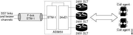
The CiscoAS5850 supports SS7 F-links (fully associated links) over a TDM interface (E1, T1, channelized T3 or STM-1). The SS7 signaling channels are not processed on the CiscoAS5850, but are hairpinned (a process also known as drop & insert) to a Call Agent over one or more other TDM interfaces.
Figure 5-3 shows the SS7 F-link being terminated on the STM-1 trunk card on the Cisco AS5850. Since the STM-1 trunk card has no connection to the SLTs, the timeslot carrying F-link on an E1 in STM-1 is "hairpinned" to a timeslot on an E1 controller on the 24-port E1 trunk. This E1 on the 24-port E1 trunk is then connected to the SLT to send the SS7 traffic to the SLT.
The signaling channels are terminated on the SLT and MTP3 messages are backhauled to the call agent.
Figure 5-3 F-links Through the Cisco AS5850
Use the following steps to connect the signaling channels from an SS7 F-Link to T1/E1 trunks that are terminated on an SLT:
Example configuration:
The following example connects a signaling channel from a channelized STM-1 trunk terminated on slot 1 to an E1 trunk terminated on slot 3. Timeslot 15 from an E1 channel on the STM-1 trunk is connected to timeslot 1 on the E1 trunk by using the connect command:
AS5850(config)# controller e1 1/0.1:2
AS5850(config-controller)# tdm-group 14 timeslots 15
AS5850(config-controller)# exit
AS5850(config)# controller e1 3/1
AS5850(config-controller)# tdm-group 0 timeslot 1
AS5850(config-controller)# exit
AS5850(config)# connect tdm_connection e1 1/0.1:2 14 e1 3/1 0
Note
•
•
•
•
•
Upgrading Cisco IOS Images
Cisco IOS Release 12.1(5)XV or later is required for using universal port cards (UPCs) on the Cisco AS5850. The required image should have been shipped with your UPC.
If you intend to configure your system in handover-split mode to achieve maximal availability, you need to run an image that supports high availability—Cisco IOS Release 12.2(2)XB or later—on both RSC cards. See the "Split Modes" section for instructions on how to upgrade to and configure for high availability.
You can upgrade your Cisco IOS software by using the same instructions as for upgrading unbundled firmware files, in the following section.
Upgrading SPE Firmware
At startup, UPCs copy a Cisco IOS software-compatible version of SPE firmware to the installed SPEs. By default, the SPE-firmware version bundled with the current version of the Cisco IOS software is loaded, but the SPEs can be configured to use unbundled SPE-firmware files.
Note
You can acquire new SPE firmware in the following ways:
•
•
•
After you have the new firmware, you can configure different firmware versions onto individual SPEs or ranges of SPEs. You can also configure different upgrade methods.
Obtaining SPE Firmware
You can obtain SPE firmware in one of the following ways:
•
•
–
–
Upgrade Commands
There are several commands you can use to upgrade SPE firmware. For examples on use of the commands, see the following sections:
•
•
•
Note
Choosing an SPE-Firmware Update or Upgrade Strategy
Cisco suggests that you choose one of the following two strategies:
•
•
SPE Firmware Upgrade Scenarios
Table 5-10 shows scenarios that can occur when you upgrade Cisco IOS software or SPE firmware.
Table 5-10 SPE-Firmware Upgrade Scenarios
1
You receive a new gateway from the Cisco factory.
No action needed. The factory loads and maps a compatible version of SPE firmware.1
2
You update Cisco IOS software, and you decide to use the SPE-firmware version selected by Cisco IOS software.
Update Cisco IOS software. No further action is needed; Cisco IOS software automatically downloads either its bundled version or a mapped version from system Flash memory.2
3
You update Cisco IOS software, and you decide not to use the SPE firmware selected by Cisco IOS software.
Update Cisco IOS software. Then copy the desired version of SPE-firmware file to system Flash memory and configure the desired SPEs to use the firmware. See the "Copying SPE Firmware from Your PC to the SPEs" section for details.
4
The SPEs are running an SPE-firmware version from system Flash memory that is different from the version bundled with Cisco IOS software. You decide to revert to the bundled version.
Use the no form of the firmware filename SPE configuration command to revert to the bundled image.
Note
5
Cisco releases new SPE firmware, which is a later version from the version currently running on the SPEs. You decide to use the newest firmware.3
Copy the desired SPE-firmware version to system Flash memory. Then configure the SPEs to use that firmware file. See the "Copying SPE Firmware from a Local TFTP Server" section for details.
1 To determine the SPE-firmware version in your system, use the show spe version command.
2 In part, Cisco IOS software bases this decision on the last copy command issued.
3 Cisco might ship this SPE firmware on a diskette packed with the spare carrier card.
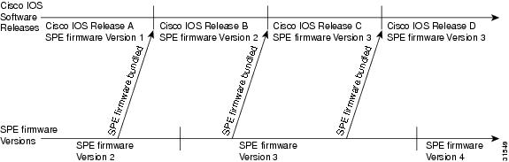
Figure 5-4 shows a location on the release timeline where updates might take place. Table 5-11 explains the resulting versions of Cisco IOS software and SPE firmware.
Figure 5-4 Release Timeline for Cisco IOS Software and SPE Firmware
Table 5-11 Resulting Versions of Cisco IOS Software and SPE Firmware
1
You upgrade Cisco IOS software to Release B:
•
•
•
•
SPE firmware Version 2•
SPE firmware Version 2•
SPE firmware Version 12
You upgrade Cisco IOS software to Release C. (Cisco IOS software uses mapping from last copy command at Time 1).1
Cisco IOS Release C
SPE firmware Version 13
New SPE firmware Version 4 is released, you copy the file to system Flash memory, enter copy flash modem, and specify SPE firmware Version 4.
Cisco IOS Release C
SPE firmware Version 44
You upgrade Cisco IOS software to Release D.
Cisco IOS Release D
SPE firmware Version 4
1 This example assumes that the last copy command was copy flash modem, and SPE firmware Version 1 was specified.
Displaying SPE Firmware Versions
Use the show spe version command to list the versions of SPE firmware that are running on the SPEs, residing in system Flash memory, and bundled with Cisco IOS software. This helps you decide if you need to change the version running on the modems.
The following example displays command output for a system with one 324 universal port card:
AS5850# show spe versionIOS-Bundled Default Firmware-Filename Version Firmware-Type===================================== ======= =============system:/ucode/np_spe_firmware1 0.6.6.9 SPE firmwareOn-Flash Firmware-Filename Version Firmware-Type========================== ======= =============slot0:np.spe_36 0.6.6.5 SPE firmwareSPE-# SPE-Type SPE-Port-Range Version UPG Firmware-Filename4/00 CSMV6 0000-0005 0.6.6.9 N/A ios-bundled default4/01 CSMV6 0006-0011 0.6.6.9 N/A ios-bundled default4/02 CSMV6 0012-0017 0.6.6.9 N/A ios-bundled default4/03 CSMV6 0018-0023 0.6.6.9 N/A ios-bundled default4/04 CSMV6 0024-0029 0.6.6.9 N/A ios-bundled default4/05 CSMV6 0030-0035 0.6.6.9 N/A ios-bundled default...4/44 CSMV6 0264-0269 0.6.6.9 N/A ios-bundled defaultUpgrading SPE Firmware from the Cisco.com TFTP Server
You can upgrade SPE firmware from the Cisco.com TFTP server by completing the following two tasks:
1.
2.
Note
Downloading SPE Firmware from Cisco.com
Note
http://www.cisco.com/public/sw-center/You can download Cisco IOS software from the Cisco.com TFTP server using an Internet browser or an FTP application.
Note
Using an Internet Browser
Step 1
Step 2
http://www.cisco.com/public/sw-center/Step 3
Step 4
Step 5
Step 6
Step 7
Using an FTP Application
Note
http://www.cisco.com/cgi-bin/ibld/all.pl?i=support&c=3.
Step 1
terminal> ftp cco.cisco.comConnected to cio-sys.cisco.com.220-220- Cisco Connection Online | | Cisco Systems, Inc.220- Email: cco-team@cisco.com ||| ||| 170 West Tasman Drive220- Phone: +1.800.553.2447 .:|||||:..:|||||:. San Jose, CA 95134220-220- NOTE: As of February 1,1997 ftp.cisco.com will now point to this220- service. Please be advised. To use the former ftp.cisco.com after220- February 1, connect to ftpeng.cisco.com220-220- You may login with:220- + Your CCO username and password, or220- + A special access code followed by your e-mail address, or220- + "anonymous" followed by your e-mail address for guest access.220-220 cio-sys FTP server (CIOESD #103 Sun Dec 15 14:43:43 PST 1996) ready.Step 2
Name (cco.cisco.com:harry): harry331 Password required for harry.Password: letmein230-#############################################################230-# Welcome to the Cisco Systems CCO FTP server.230-# This server has a number of restrictions. If you are not familiar230-# with these, please first get and read the /README or /README.TXT file.230-# http://www.cisco.com/acs/info/cioesd.html for more info.230-#############################################################230-230- ***** NOTE: As of February 1, 1997, "cco.cisco.com", *****230- ***** "www.cisco.com" and "ftp.cisco.com" are now all *****230- ***** logical names for the same machine. *****230- ***** *****230- ***** The old "ftp.cisco.com" is an entirely *****230- ***** different machine, which is now known as *****230- ***** "ftpeng.cisco.com" or "ftp-eng.cisco.com". *****230- ***** *****230- ***** In general, "ftpeng.cisco.com" is used only for *****230- ***** distribution of Cisco Engineering-controlled *****230- ***** projects, such as beta programs, early field *****230- ***** trials, developing standards documents, etc. *****230- ***** *****230- ***** Be sure to confirm you have connected to *****230- ***** the machine you need to interact with. *****230-230- If you have any odd problems, try logging in with a minus sign (-) as230- the first character of your password. This will turn off a feature230- that may be confusing your ftp client program.230- Please send any questions, comments, or problem reports about this230- server to cco-team@cisco.com.230-230- NOTE:230- o To download files from CCO, you must be running a *passive-mode*230- capable FTP client.230- o To drop files on this system, you must cd to the /drop directory.230- o Mirrors of this server can be found at230-230- + ftp://www-europe.cisco.com European (Amsterdam)230- + ftp://www-fr.cisco.com France (Paris)230- + ftp://www-au.cisco.com Australia (Sydney)230- + ftp://www-jp.cisco.com Japan (Tokyo)230- + ftp://www-kr.cisco.com Korea (Seoul)230-230-Please read the file README230- it was last modified on Sat Feb 1 12:49:31 1997 - 163 days ago230 User harry logged in. Access restrictions apply.Remote system type is UNIX.Using binary mode to transfer files.Step 3
ftp> cd /cisco/access/5850250-Please read the file README250- it was last modified on Tue May 27 10:07:38 1997 - 48 days ago250-Please read the file README.txt250- it was last modified on Tue May 27 10:07:38 1997 - 48 days ago250 CWD command successful.Step 4
ftp> ls227 Entering Passive Mode (192,31,7,130,218,128)150 Opening ASCII mode data connection for /bin/ls.total 2688drwxr-s--T 2 ftpadmin ftpcio 512 Jun 30 18:11 .drwxr-sr-t 19 ftpadmin ftpcio 512 Jun 23 10:26 ..lrwxrwxrwx 1 root 3 10 Aug 6 1996 README ->README.txt-rw-rw-r-- 1 root ftpcio 2304 May 27 10:07 README.txt-r--r--r-- 1 ftpadmin ftpint 377112 Jul 10 18:08 SPE-firmware.x.x.x.bin-r--r--r-- 1 ftpadmin ftpint 635 Jul 10 18:08 SPE-firmware.3.1.30.readme226 Transfer complete.Step 5
ftp> binary200 Type set to I.Step 6
Step 7
ftp> quitGoodbye.Step 8
server% ls -altotal 596-r--r--r-- 1 280208 Jul 10 18:08 SPE-firmware.x.x.x.binserver% pwd/auto/tftpbootStep 9
Copying SPE Firmware from a Local TFTP Server
The procedure for copying the SPE-firmware file from your local TFTP server to the Cisco AS5850 includes two steps. First, transfer the SPE firmware to the gateway's Flash memory. Then, configure the SPEs to use the upgrade firmware. The upgrade occurs automatically, either when you leave configuration mode or as specified in the configuration.
You need perform these steps only once. Because SPE firmware is configurable for individual SPEs or ranges of SPEs, the Cisco IOS software automatically copies the firmware to each SPE whenever the gateway restarts.
The following procedure assumes that your terminal is connected directly to the console port on the Cisco AS5850 RSC. Use these steps to download SPE firmware to Flash memory.
Step 1
AS5850# show flashSystem flash directory:File Length Name/status1 4530624 c5850-p9-mz[498776 bytes used, 16278440 available, 16777216 total]16384K bytes of processor board System flash (Read/Write)Step 2
AS5850# copy tftp flashSystem flash directory:File Length Name/status1 4530624 images/c5850-p9-mz[498776 bytes used, 16278440 available, 16777216 total]Address or name of remote host [255.255.255.255]? juraiSource file name? np_6_83_2.speDestination file name [np_6_83_2.spe]?Accessing file 'np_6_83_2.spe' on 255.255.255.255...Loading np_6_83_2.spe from 2.2.0.1 (via Ethernet0): ! [OK]Erase flash device before writing? [confirm] noCopy 'np_6_83_2.spe' from serveras 'np_6_83_2.spe' into Flash WITHOUT erase? [yes/no] yesLoading images/np_6_83_2.spe from 2.2.0.1 (via Ethernet0):!!!!!!!!!!!!!!!!!!!!!!!!!!!!!!!!!!!!!!!!!!!!!!!!![OK - 249108/16278440 bytes]Verifying checksum... OK (0xE009)Flash device copy took 00:00:02 [hh:mm:ss]Step 3
AS5850# dir flash:Directory of disk0:/3 -rw- 325539 Jan 01 2000 04:33:44 np_6_83_2.spe83 -rw- 8987568 Jan 02 2000 02:45:30 c5850-p9-mz31916032 bytes total (13320192 bytes free)Step 4
AS5850# copy tftp flashSystem flash directory:File Length Name/status1 4530624 images/c5850-p9-mz[498776 bytes used, 16278440 available, 16777216 total]Address or name of remote host [255.255.255.255]? juraiSource file name? SPE-firmware.x.x.x.x.binDestination file name [SPE-firmware.x.x.x.x.bin]?Accessing file 'SPE-firmware.x.x.x.x.bin' on 255.255.255.255...Loading SPE-firmware.x.x.x.x.bin from 2.2.0.1 (via Ethernet0): ! [OK]Erase flash device before writing? [confirm] noCopy 'SPE-firmware.x.x.x.x.bin' from serveras 'SPE-firmware.x.x.x.x.bin' into Flash WITHOUT erase? [yes/no] yesLoading images/SPE-firmware.x.x.x.x.bin from 2.2.0.1 (via Ethernet0):!!!!!!!!!!!!!!!!!!!!!!!!!!!!!!!!!!!!!!!!!!!!!!!!![OK - 249108/16278440 bytes]Verifying checksum... OK (0xE009)Flash device copy took 00:00:02 [hh:mm:ss]To configure the SPEs to use an upgraded firmware file, complete the following steps:
Step 1
AS5850# configure terminalEnter configuration commands, one per line. End with CNTL/Z.AS5850(config)#You are in global configuration mode when the prompt changes to AS5850(config)#.
Step 2
AS5850(config)# spe slot/speorAS5850(config)# spe slot/spe slot/speYou are in SPE configuration mode when the prompt changes to AS5850(config-spe)#.
Step 3
AS5850(config-spe)# firmware location filenameStep 4
AS5850(config-spe)# firmware upgrade [busyout | recovery | reboot]Step 5
AS5850(config-spe)# exitAS5850(config)#Step 6
AS5850(config)# Ctrl-ZAS5850#Step 7
AS5850# copy running-config startup-config
Upgrading SPE Firmware from Diskettes
This section describes how to copy SPE firmware from diskettes to your hard disk in a PC environment, and then upload the firmware to the SPEs. The steps are similar whether you are using a Macintosh or UNIX workstation.
Note
Copying SPE Firmware to Your PC
Step 1
Step 2
Step 3
Copying SPE Firmware from Your PC to the SPEs
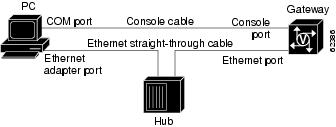
If you are using a PC running Microsoft Windows, upgrading SPE firmware from a hard drive onto a Cisco AS5850 involves setting up a TFTP application on your PC, connecting your PC and the gateway, establishing a HyperTerminal session, pinging the PC and gateway, and finally, copying the SPE firmware to the gateway. See the following sections for details.
Setting Up a TFTP Application on the PC
Step 1
Note
http://www.cisco.com/public/sw-center/sw-other.shtmlStep 2
Step 3
a.
b.
c.
Note
Connecting Your PC and the Gateway
Step 1
Figure 5-5 Connecting a PC and a Gateway
Note
Step 2
Step 3
Establishing a HyperTerminal Session
Step 1
Step 2
Step 3
Step 4
Step 5
•
•
•
•
•
Step 6
Step 7
Note
Pinging the PC and Gateway
Step 1
a.
b.
c.
d.
Note
Step 2
AS5850# enablePassword: passwordAS5850#Step 3
AS5850# ping 172.16.1.1The gateway displays five exclamation points (!) if everything is working and five dots (.) if there is a problem. In the latter case, check the cabling between the RSC and the PC and check the gateway configuration.
Uploading SPE Firmware to the Gateway
The procedure for copying the SPE-firmware file from your PC set up as a local TFTP server to the gateway system Flash memory requires that you transfer the firmware first to the gateway and from there to the SPEs.
Once you perform this procedure, you should not have to do so again. Because the code runs from the SPEs, the Cisco IOS software must automatically copy the firmware to each SPE whenever the gateway restarts.
Step 1
a.
AS5850# show flashSystem flash directory:File Length Name/status1 4530624 c5850-p9-mz[498776 bytes used, 16278440 available, 16777216 total]16384K bytes of processor board System flash (Read/Write)b.
AS5850# copy tftp flashSystem flash directory:File Length Name/status1 4530624 images/c5850-p9-mz[498776 bytes used, 16278440 available, 16777216 total]Address or name of remote host [255.255.255.255]? juraiSource file name? SPE-firmware.x.x.x.x.binDestination file name [SPE-firmware.x.x.x.x.bin]?Accessing file 'SPE-firmware.x.x.x.x.bin' on 255.255.255.255...Loading SPE-firmware.x.x.x.x.bin from 2.2.0.1 (via Ethernet0): ! [OK]Erase flash device before writing? [confirm] noCopy 'SPE-firmware.x.x.x.x.bin' from serveras 'SPE-firmware.x.x.x.x.bin' into Flash WITHOUT erase? [yes/no] yesLoading images/SPE-firmware.x.x.x.x.bin from 2.2.0.1 (via Ethernet0):!!!!!!!!!!!!!!!!!!!!!!!!!!!!!!!!!!!!!!!!!!!!!!!!![OK - 249108/16278440 bytes]Verifying checksum... OK (0xE009)Flash device copy took 00:00:02 [hh:mm:ss]c.
AS5850# show flashSystem flash directory:File Length Name/status1 4530624 c5850-p9-mz2 210104 SPE-firmware.x.x.x.x.bin[747948 bytes used, 16029268 available, 16777216 total]16384K bytes of processor board System flash (Read/Write)Step 2
a.
AS5850> enablePassword: passwordAS5850#AS5850# configure terminalEnter configuration commands, one per line. End with CNTL/Z.AS5850(config)#You are in global configuration mode when the prompt changes to AS5850(config)#.
b.
AS5850(config)# spe slot/speorAS5850(config)# spe slot/spe slot/speYou are in SPE configuration mode when the prompt changes to AS5850(config-spe)#.
c.
AS5850(config-spe)# firmware filename location filenamed.
AS5850(config-spe)# firmware filename upgrade busyoute.
AS5850(config-spe)# exitAS5850(config)#f.
AS5850(config)# Ctrl-ZAS5850#g.
AS5850# copy running-config startup-config
Using the SPE Firmware Bundled with the Cisco IOS Software
If you decide to use the version of SPE firmware that is bundled with Cisco IOS software instead of the version already mapped to your ports, use this procedure to update firmware on the SPEs in your gateway.
Step 1
AS5850> enablePassword: passwordAS5850#AS5850# configure terminalEnter configuration commands, one per line. End with CNTL/Z.AS5850(config)#You are in global configuration mode when the prompt changes to AS5850(config)#.
Step 2
AS5850(config)# spe slot/speorAS5850(config)# spe slot/spe slot/speYou are in SPE configuration mode when the prompt changes to AS5850(config-spe)#.
Step 3
AS5850(config-spe)# no firmware filename location filenameStep 4
AS5850(config-spe)# firmware filename upgrade [busyout | recovery | reboot]Step 5
AS5850(config-spe)# exitAS5850(config)#Step 6
AS5850(config)# Ctrl-ZAS5850#Step 7
AS5850# copy running-config startup-configThis process does not delete any existing SPE firmware that resides in system Flash memory, in case you later want to revert to it. If you decide to delete the code from system Flash memory, remember that all files in system Flash memory will be deleted. Therefore save and restore any important files (for example, the Cisco IOS software image).
Note
Split Modes
If you have two RSCs in your gateway, you can configure your Cisco AS5850 into one of two redundancy modes: classic split or handover split.
•
•
Alternately, to use system resources most efficiently, you can operate with one of the two RSCs initially and intentionally in extraload state. In this configuration, RSC A initially controls all slots in the chassis and RSC B is in standby mode, ready to take over should RSC A fail. This allows you to overcome the limits of normal classic-split mode in which, because only six slots are available per RSC, an optimal combination of trunk and DSP cards is difficult to achieve.
Note
A single RSC can support up to two CT3 trunk cards, although it can be released from this restriction. The number of CT3, T1, E1, or STM-1 trunk cards that your system can handle depends on the split mode in which it is configured to operate:
•
•
In either case, the number of trunk cards allowed should not exceed the performance load of the handling RSC card. For further information about performance loads, refer to the "Capacities" section on page 1-3.
Classic-Split Mode
Classic-split mode provides maximal throughput with no load sharing. Operating a Cisco AS5850 in classic-split mode is the same as having two Cisco AS5850s, each with a separate set of cards.
Note
Configuring Classic-Split Mode
Follow these steps on each RSC to configure your system to operate in classic-split mode. Classic-split mode is the system's default mode; it is normally not necessary to configure this mode unless you are returning to it from handover-split mode.
Caution
Step 1
Step 2
Step 3
Step 4
Step 5
Note
Classic-Split Configuration Commands
AS5850# configuration terminal
AS5850(config)# redundancy
AS5850(config-red)# mode classic-splitEnters configuration-redundancy mode, then selects classic-split (the default) mode.
Classic-Split Show Commands
In classic-split mode, most show commands (with exceptions noted below) display information for only those slots owned by the RSC; they look and behave as they would if there were no cards in the slots that the RSC does not own. To see show command information for a slot, you must connect to the RSC that owns that slot.
I
Managing a Classic Split
Note that classic-split mode is the default mode. If you do not configure a mode, your system defaults to classic-split mode.
A classic-split system appears to SNMP management applications as two separate Cisco AS5850s. You must conduct a console session for each RSC (two console sessions in total) to configure your splits. The system controller manages a classic-split configuration as two separate Cisco AS5850 gateways.
Network management systems (NMSs) such as the Cisco Universal Gateway Manager (Cisco UGM) are available that provide a single system view of multiple points of presence (POPs) as they monitor performance and log accounting data. An NMS has a graphical user interface (GUI); runs on a UNIX SPARC station; and includes a database-management system, polling engine, trap management, and map integration. The NMS can be installed at a remote facility so that you can access multiple systems through a console port or Web interface.
In classic-split mode, it is desirable—and, with an NMS, essential—to use four unique IDs, one for each RSC and one for each set of slots. In some cases, however, it is sufficient to use the same ID for the two RSCs.
No new management-information bases (MIBs) or MIB variables are required for classic-split configuration.
Handover-Split Mode
Handover-split mode provides maximal availability with load sharing. If an RSC should ever go down, the other RSC automatically takes over the slots and cards controlled by the failed RSC. This form of redundancy prevents a single point of failure, subsequent downtime, and required user intervention to resolve unrecoverable hardware faults.
You can detect if an RSC is in extraload with control of the entire chassis resources in either of two ways:
•
•
Caution
Upgrading to a High-Availability Cisco IOS Release
Verify that you have a Cisco IOS release that supports high availability (Cisco IOS Release 12.2(2)XB or higher). If you do not, proceed with one of the following upgrade scenarios.
Note
Upgrading from a Compatible (High-Availability) Image
Tip
•
Step 1
a.
b.
Step 2
Step 3
Step 4
a.
b.
Step 5
Step 6
Upgrading from an Incompatible (Nonhigh-Availability) Image
Caution
Tip
Step 1
Step 2
a.
b.
Wait for both reloads to complete.
Step 3
a.
b.
Configuring Handover-Split Mode
Follow these steps to configure your system to operate in handover-split mode.
Caution
Tip
Step 1
Step 2
Step 3
Step 4
a.
b.
c.
d.
Note
Step 5
a.
b.
Note
Configuring Handover-Split Mode in Extraload
To use system resources most efficiently, you can operate your Cisco AS5850 with one of the two RSCs initially and intentionally in extraload state. In this configuration, RSC A initially controls all slots in the chassis and RSC B is in standby mode, ready to take over should RSC A fail. This allows you to overcome the limits of normal classic-split mode in which, because only six slots are available per RSC, an optimal combination of trunk and DSP cards is difficult to achieve.
Note
Procedures for configuring your system to operate in extraload are the same as those for configuring it to operate in normal handover-split mode. Simply use the no dial-config-guidelines command to remove the restriction on the number of trunk cards allowed.
If you use your system in conjunction with a Cisco SC2200 for SS7 signaling, configure the system with both RSCs in active state. Once configuration is complete, put one RSC into extraload by using the redundancy handover shelf-resources command on the other RSC. For more information on this configuration, see the "Managing a Handover Split with SS7" section.
Handover-Split Configuration Commands
Note
Handover-Split Show Commands
Managing a Handover Split with SS7
Your Cisco AS5850 VoIP system may employ a Cisco SC2200 signaling controller, which provides a Common Channel Signaling System 7 (SS7/C7) interface between your H.323 VoIP and dial-access applications and the public switched telephone network (PSTN).
The SS7 network is an overlay signaling network (using a dedicated, separate signaling path) for carrying signaling messages used to connect calls. SS7/C7 is the common-channel signaling standard deployed on the SS7 network. With a Cisco SC2200 and SS7 signaling, you can optimize your network for both voice and data traffic and save drastically on interconnect fees compared to what you would incur for ISDN PRI. (ISDN PRI combines both signaling and bearer traffic on the same T1 or E1 facility. Normally one channel on the facility, the D-channel, provides ISDN signaling.)
In handover-split mode, each RSC on the Cisco AS5850 has its own IP address. Yet the Cisco SC2200 is static—that is, upon handover, the Cisco SC2200 fails to recognize that trunks and circuit identification codes (CICs) associated with one RSC under its IP address have been transferred to the other RSC under its IP address. (The CIC is the part of a CCS/SS7 signaling message used to identify the circuit that is being established between two signaling points.)
To avoid problems, you must configure two redundant-link-manager (RLM) groups (one active and one standby) per RSC—four groups in all—that the Cisco AS5850 can automatically enable or disable as appropriate.
Configuring RLM Groups
To configure RLM groups, follow these steps:
Step 1
Step 2
Note
Step 3
The number and ownership of CICs is implicitly defined by the number and type of trunk cards controlled by the RSC. For each card type, the maximum number of CICs is as follows:
24-channelized T1/E1
For T1: 24 * 24 = 576
For E1: 24 * 32 (30 clear + 2 signaling/control) = 768
Channelized T3
672
The following two sample configurations (displayed by use of the show running-config command from each RSC) shows a Cisco AS5850 that has two E1 trunk cards, one belonging to RSC A with 24 interfaces and the other belonging to RSC B with 8 interfaces:
controller E1 9/0pri-group timeslots 1-31 nfas_d primary nfas_int 0 nfas_group 0...controller E1 9/23pri-group timeslots 1-31 nfas_d none nfas_int 23 nfas_group 1controller E1 2/0pri-group timeslots 1-31 nfas_d primary nfas_int 0 nfas_group 1...controller E1 2/7pri-group timeslots 1-31 nfas_d none nfas_int 7 nfas_group 1The number and ownership of CICs is as follows:
•
•
Step 4
a.
–
–
RSC A owns group 1 (CICs 0-49) in normal operation, but not group 2 (CICs 50-99).
b.
–
–
Step 5
a.
–
–
RSC B owns group 2 (CICs 50-99) in normal operation, but not group 1 (CICs 0-49).
b.
–
–
Step 6
For example, if RSC A is has an IP address of ipA and RSC B has an IP address of ipB, configure the Cisco SC2200 as follows:
•
•
Tip
–
http://www.cisco.com/univercd/cc/td/doc/product/access/sc/r2/index.htm•
–
http://www.cisco.com/univercd/cc/td/doc/product/access/sc/rel7/soln/das22/gateway/index.htm–
http://www.cisco.com/univercd/cc/td/doc/product/access/sc/r2/index.htmThe end result of these steps is that you now have four links:
•
•
•
•
Under normal-mode operation, both RSCs are active.
•
–
–
•
–
–
If RSC B fails, link 4 on RSC B moves from active (no shutdown) to standby (shutdown) and link 3 on RSC A moves from standby (shutdown) to active (no shutdown).
•
–
–
•
–
RSC B, when it once again becomes active, enables link 4 again, which causes suppression of link 3 to standby (shutdown).
Table 5-12 summarizes link status under normal and failure conditions.
Sample RLM-Group Link Configurations
Cisco SC2200 Configuration
A sample Cisco SC2200 configuration might look like this:
; Adding IPLink to define links between gateway and SC2200; Each NAS-Service has multiple RLM groups to associate. Use different port number; (3001, 3003) to configure them.; nassrvc1 associates to RLM0(uut1) and RLM3(uut2); nassrvc2 associates to RLM2(uut2) and RLM1(uut1);prov-add:iplnk:name="gw5850-1-rlm0",if="eth1-if",ipaddr="IP_Addr1",port=3001,peeraddr="192.168.78.56",peerport=3001,svc="nassrvc1",desc="Link between gw5850-1 and SC2200-1";prov-add:iplnk:name="gw5850-2-rlm3",if="eth1-if",ipaddr="IP_Addr1",port=3001,peeraddr="192.168.78.58",peerport=3001,svc="nassrvc1",desc="Link between gw5850-2 and SC2200-1";prov-add:iplnk:name="gw5850-2-rlm2",if="eth1-if",ipaddr="IP_Addr1",port=3003,peeraddr="192.168.78.58",peerport=3003,svc="nassrvc2",desc="Link between gw5850-2 and SC2200-1";prov-add:iplnk:name="gw5850-1-rlm1",if="eth1-if",ipaddr="IP_Addr1",port=3003,peeraddr="192.168.78.56",peerport=3003,svc="nassrvc2",desc="Link between gw5850-1 and SC2200-1"This example assumes for simplicity that your system has only one Cisco SC2200. Normally, Cisco SC2200s are deployed in pairs to provide failover redundancy, and the links to the standby system are activated when the active system fails. As you configure your Cisco SC2200s, simply duplicate links within a single RLM group.
Cisco AS5850 Configuration
The relevant portions of a sample Cisco AS5850 RSC configuration might look like this for RSCs A and B respectively:
! Configuration for RSC A (as displayed with show running-config command):rlm group 0server vsc-alink address 192.168.78.100 source GigabitEthernet6/0 weight 1!rlm group 1shutdownserver vsc-alink address 192.168.78.100 source GigabitEthernet6/0 weight 2! Configuration for RSC B (as displayed with show running-config command):rlm group 2protocol rlm port 3002server vsc-alink address 192.168.78.100 source GigabitEthernet7/0 weight 1!rlm group 3shutdownserver vsc-alink address 192.168.78.100 source GigabitEthernet7/0 weight 2Sample Handover-Split Configuration
The following example shows a startup configuration that supports high availability. Note, in the sections on resource-pool range and controller numbers, that every card in the chassis is configured.
AS5850RSCA# show startup-configversion 12.2no service padservice timestamps debug datetime msecservice timestamps log datetime msecno service password-encryptionservice compress-config!hostname RouterA!redundancymode handover-splitaaa new-model!!aaa group server tacacs+ redline2!aaa group server radius RADIUS-GROUPserver 172.22.51.9 auth-port 1645 acct-port 1646!aaa authentication login CONSOLE noneaaa authentication login VTY noneaaa authentication ppp default group RADIUS-GROUPaaa authentication ppp RADIUS-LIST group RADIUS-GROUPaaa authorization exec CONSOLE noneaaa authorization exec RADIUS-LIST group RADIUS-GROUPaaa authorization network default group RADIUS-GROUP if-authenticatedaaa authorization network RADIUS-LIST group RADIUS-GROUP if-authenticatedaaa accounting network default start-stop group RADIUS-GROUPaaa nas port extendedaaa session-id commonenable password xxx!username RouterB password 0 xxxusername 54006username 54006_1 password 0 xxxusername RouterA password 0 xxxusername 54006_d_119 password 0 xxx!resource-pool enable!resource-pool group resource group1range port 1/0 1/323range port 4/20 4/30!resource-pool group resource group2range port 9/0 9/215range port 10/0 10/120!resource-pool group resource digital_group_6range limit 207!resource-pool group resource digital_grouprange limit 116!resource-pool group resource vpdn_digrange limit 92!resource-pool profile customer 54006_customerlimit base-size alllimit overflow-size 0resource group1 speechdnis group 54006_dnis!resource-pool profile customer 54007_customerlimit base-size alllimit overflow-size 0resource group2 speechdnis group 54007_dnis!resource-pool profile customer 54006_customer_synclimit base-size alllimit overflow-size 0resource digital_group_6 digitaldnis group 54006_sync_dnis!resource-pool profile customer 54007_synclimit base-size alllimit overflow-size 0resource digital_group digitaldnis group 54007_sync_dnis!resource-pool profile customer 54007_sync_vpdnlimit base-size alllimit overflow-size 0resource vpdn_dig digitaldnis group 54007_sync_vpdn_dnisclock timezone PST -7dial-tdm-clock priority 8 trunk-slot 9 ds3-port 0 port 1dial-tdm-clock priority 10 trunk-slot 4 ds3-port 0 port 1spe country t1-default!spe link-info poll voice 5!ip subnet-zeroip cef distributedip ftp source-interface FastEthernet6/0ip ftp username rootip ftp password xxxxxno ip domain-lookup!vpdn enable!vpdn-group 1request-dialinprotocol l2fsource-ip 30.0.0.1!chat-script dial "" "ATZ" OK "ATDT\T" TIMEOUT 60 CONNECTisdn switch-type primary-5ess!controller T3 4/0framing c-bitcablelength 224t1 1-28 controller!controller T1 4/0:1framing esfpri-group timeslots 1-24!controller T1 4/0:2framing esfpri-group timeslots 1-24!controller T1 4/0:3framing esfpri-group timeslots 1-24!...controller T1 4/0:28shutdownframing esfpri-group timeslots 1-24!controller T3 9/0framing c-bitcablelength 224t1 1-28 controller!controller T1 9/0:1framing esfds0-group 0 timeslots 1-24 type e&m-fgb dtmf dnis!controller T1 9/0:2framing esfds0-group 0 timeslots 1-24 type e&m-fgb dtmf dnis!controller T1 9/0:3framing esfds0-group 0 timeslots 1-24 type e&m-fgb dtmf dnis!...controller T1 9/0:12framing esfds0-group 0 timeslots 1-24 type e&m-fgb dtmf dnis!controller T1 9/0:13framing esfpri-group timeslots 1-24!...controller T1 9/0:21framing esfpri-group timeslots 1-24!controller T1 9/0:22shutdownframing esfds0-group 0 timeslots 1-24 type e&m-fgb dtmf dnis!...controller T1 9/0:28shutdownframing esfds0-group 0 timeslots 1-24 type e&m-fgb dtmf dnis!!!interface Loopback0ip address 111.111.111.11 255.255.255.0no ip mroute-cache!interface Serial4/0:1:23no ip addressencapsulation pppip mroute-cacheisdn switch-type primary-5essisdn incoming-voice modem!interface Serial4/0:2:23no ip addressencapsulation pppip mroute-cacheisdn switch-type primary-5essisdn incoming-voice modem!interface Serial4/0:3:23no ip addressencapsulation pppip mroute-cacheisdn switch-type primary-5essisdn incoming-voice modem!...interface Serial4/0:10:23no ip addressencapsulation pppip mroute-cacheisdn switch-type primary-5essisdn incoming-voice modem!interface Serial4/0:11:23no ip addressencapsulation pppip mroute-cacheisdn switch-type primary-5essisdn incoming-voice modem!interface Serial9/0:21:23ip unnumbered Loopback0encapsulation pppip mroute-cachedialer rotary-group 1dialer-group 1isdn switch-type primary-5ess!interface Group-Async0ip unnumbered Loopback0encapsulation pppdialer in-banddialer idle-timeout 36000 eitherdialer string 6003dialer-group 1async default routingasync mode dedicatedpeer default ip address pool KRAMERppp max-bad-auth 3ppp authentication chap pap callin RADIUS_LISTppp chap hostname RouterBppp chap password 7 xxxxxgroup-range 9/00 11/323!interface Group-Async1ip unnumbered Loopback0encapsulation pppdialer in-banddialer idle-timeout 36000 eitherdialer string 6003dialer-group 1async default routingasync mode dedicatedpeer default ip address pool KRAMER1ppp max-bad-auth 3ppp authentication chap pap callin RADIUS_LISTppp chap hostname RouterAppp chap password 7 xxxxxgroup-range 1/00 4/215!interface Dialer0ip unnumbered Loopback0encapsulation pppdialer in-banddialer idle-timeout 36000 eitherdialer string 6003dialer-group 1peer default ip address pool KRAMER1_d_mno fair-queueno cdp enableppp authentication chap pap callin RADIUS_LISTppp chap hostname RouterAppp chap password 7 xxxxxppp multilink!interface Dialer1ip unnumbered Loopback0encapsulation pppdialer in-banddialer idle-timeout 36000 eitherdialer string 6003dialer-group 1peer default ip address pool KRAMER_dno cdp enableppp max-bad-auth 3ppp authentication chap pap callin RADIUS_LISTppp chap hostname RouterBppp chap password 7 xxxxx!interface Dialer2ip unnumbered Loopback0encapsulation pppdialer in-banddialer idle-timeout 36000 eitherdialer string 6003dialer-group 1peer default ip address pool KRAMER1_dno fair-queueno cdp enableppp authentication chap pap callin RADIUS_LISTppp chap hostname RouterAppp chap password 7 xxxxx!interface Dialer5no ip addressno cdp enable!interface Dialer6no ip addressno cdp enable!interface Dialer7no ip addressno cdp enable!...interface Dialer26no ip addressno cdp enable!ip local pool KRAMER1 10.6.1.1 10.6.1.108ip local pool KRAMER1 10.6.2.1 10.6.2.108ip local pool KRAMER1 10.6.3.1 10.6.3.60ip local pool KRAMER 10.7.1.1 10.7.1.108ip local pool KRAMER 10.7.2.1 10.7.2.108ip local pool KRAMER 10.7.3.1 10.7.3.60ip local pool KRAMER1_d 10.6.4.1 10.6.4.115ip local pool KRAMER_d 10.7.4.1 10.7.4.115ip local pool KRAMER1_d_m 10.6.4.116 10.6.4.163ip classlessno ip http server!ip radius source-interface FastEthernet6/0!dialer dnis group 54006_dnisnumber 1002number 1002100212!dialer dnis group 54007_dnisnumber 38327!dialer dnis group 54006_sync_dnisnumber 6666number 6600number 6666666666!dialer dnis group 54007_sync_dnisnumber 7700number 7700000000!dialer dnis group 54007_sync_vpdn_dnisnumber 7777number 7777777777!dialer dnis group 54007_vpdn_dnisnumber 38777dialer-list 1 protocol ip permitno cdp run!tacacs-server host 152.22.51.64tacacs-server timeout 30tacacs-server key ciscosnmp-server community public RWsnmp-server enable traps rf!radius-server configure-nasradius-server host 172.22.51.9 auth-port 1645 acct-port 1646 non-standardradius-server retransmit 3radius-server attribute nas-port format cradius-server key labcall rsvp-sync!voice-port 4/0:1:D!voice-port 4/0:2:D!voice-port 4/0:3:D!...voice-port 4/0:28:D!voice-port 9/0:1:0!voice-port 9/0:2:0!voice-port 9/0:3:0!...voice-port 9/0:28:0!!line con 0password xxxxxxlogging synchronousline aux 0logging synchronousmodem InOuttransport input allline vty 0 4password xxxtransport preferred telnettransport input telnetline 1/00 4/215modem InOutno modem status-pollno modem log rs232transport preferred nonetransport input allautoselect during-loginautoselect pppline 9/00 9/215modem InOutno modem status-pollno modem log rs232transport preferred nonetransport input allautoselect during-loginautoselect pppline 10/00 11/323modem InOutno modem status-pollno modem log rs232transport preferred nonetransport input allautoselect during-loginautoselect pppend