Feedback
Table Of Contents
Replacing or Installing Dial Shelf Cards
Replacing or Installing Dial Shelf Cards
This chapter describes system component mechanical functions and emphasizes the importance of following the correct procedures to avoid unnecessary circuit card failures. This chapter is for background information only.
Online Insertion and Removal
The Cisco AS5800 universal access server supports online insertion and removal (OIR). This feature allows you to remove and replace a trunk card or port-handling card, while the system is operating, without affecting system operation.
CautionIn order to maintain traffic flow in a single dial shelf controller (DSC) configuration, the DSC shouldn't be removed while the system is operational. If the DSC is removed, the interconnect link between the DSC and router shelf will be lost and all other dial shelf cards will go down. The router console port will display the following message:
AUG 2 10:57:02.017 CST: %DSC_REDUNDANCY-3-BICLINK: Link to active DSC down
Each dial shelf card contains a female connector that connects to a male connector on the system backplane. Each male backplane connector comprises a set of tiered pins in two lengths. The backplane pins send specific signals to the system as they make contact with the card connectors. The system assesses the signals it receives and the order in which it receives them to determine what event is occurring and what task it needs to perform, such as reinitializing new interfaces or shutting down removed ones.
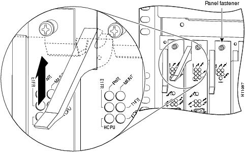
Each dial shelf card is designed with two ejector levers to be used when you install or remove a card. The function of the ejector levers is to align and securely seat the card connectors in the backplane.
Caution
Busyout Command
To remove a CT1/CE1 trunk card without dropping calls or connections, you must first take the card out of service by using the busyout command to remove DS0s and modem resources from the available pool as calls are completed. The busyout command is run on a per card (slot) basis.
The busyout command has the format busyout shelf number/slot number, where shelf number is a user-designated value from 0 to 9999 and slot number is 0 to 5. The following example shows how to busyout the card in slot 0 on shelf 5:
AS5800# busyout 5/0AS5800#If you are replacing a failed card, we recommend that you proceed as follows:
1.
2.
3.
If you are replacing a CT1/CE1 trunk card with a new CT1/CE1 trunk card of the same type in the same slot, the system software recognizes the new CT1/CE1 trunk card interfaces and brings them up automatically. No additional configuration is needed. A CT1/CE1 trunk card installed in a different slot affects the clocking source.
Note
Required Materials
You need the following supplies to install a CT1/CE1 trunk card. Contact a service representative for ordering information if you need additional materials.
•
•
•
•
•
•
•
•
Removing a Dial Shelf Card
To remove a CT1/CE1 trunk card from the (Cisco 5814) dial shelf, complete the following steps:
Warning
Caution
Caution
Step 1
Step 2
busyout shelf-number/slot-numberStep 3
Step 4
Caution
Step 5
Step 6
Figure 1-1 Using the Ejector Lever
Step 7
Caution
Step 8
Step 9
Warning
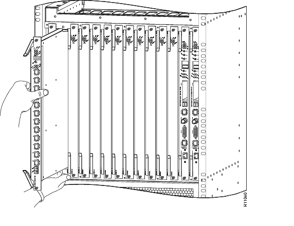
Step 10
Figure 1-2 Removing or Replacing a CT1/CE1 Trunk Card
Step 11
This completes the CT1/CE1 trunk card removal procedure. To install a CT1/CE1 trunk card, proceed to the following section, "Installing a Dial Shelf Card."
Installing a Dial Shelf Card
To install a new CT1/CE1 trunk card in the Cisco 5814 dial shelf, follow these steps:
Caution
Caution
Step 1
Caution
Step 2
Step 3
Step 4
Caution
Step 5
Caution
Step 6
Step 7
Caution
This completes the CT1/CE1 trunk card replacement procedure.