Feedback
Table Of Contents
Preparing the Dial Shelf for Rack-Mount
Removing the DC Power-Entry Modules
Removing Dial Shelf Cards and Dial Shelf Controller Cards
Installing the Rack-Mount Brackets on the Chassis
Mounting Forward Brackets for an Offset Telco Rack Installation
Distance Limitations and Interface Specifications
Maintaining Safety with Electricity
Preventing Electrostatic Discharge Damage
Preventive Site Configuration: Maintaining Normal Operation
Preparing for Installation
This chapter describes the equipment and site requirements for installing the Cisco AS5800. Before installing your access server, you should consider the power and cabling that must be in place at your installation site, the equipment needed for installation, and the environmental conditions your installation site must meet to maintain normal operation. This chapter guides you through the installation preparation process.
Warning
Only trained and qualified personnel should be allowed to install or replace this equipment. To see translations of the warnings that appear in this publication, refer to the Cisco AS5800 Universal Access Server Regulatory Compliance and Safety Information document that accompanied this device.
Site Requirements
The Cisco AS5800 is designed with an environmental monitoring system that protects the system and components from potential damage from overvoltage and overtemperature conditions. To assure normal operation and avoid unnecessary maintenance, plan your site configuration and prepare your site before installation. After installation, make sure that the site maintains an ambient temperature of 32° F through 104° F (0° C through 40° C), and keep the area around the chassis as free from dust as is practical.
The following sections address the site environment requirements for the access server.
AC and DC Power
The Cisco 5814 dial shelf and Cisco 7206 router shelf are designed to support either AC-input or DC-input power.
Caution
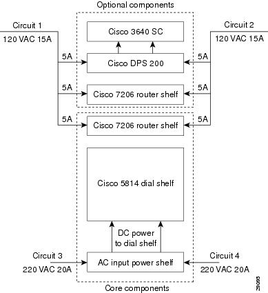
Figure 2-1 AC Power Planning
If AC power will be used, to provide full redundancy the Cisco AS5800 requires two 220 VAC 30A circuits for the Cisco 5814 dial shelf and its components, and two additional120 VAC 15A circuits for the Cisco 7206 router shelf (or shelves, if a split dial shelf configuration will be used) and the Cisco 3640 system controller (if used). See Figure 2-1.
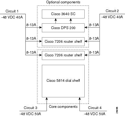
Figure 2-2 DC Power Planning
If DC power will be used, to provide full redundancy the Cisco AS5800 requires two DC power circuits providing up to 54A at -48VDC for theCisco 5814 dial shelf and its components, and two additional 40A -48VDC circuits for the router shelf (or shelves, if a split dial shelf configuration will be used) and the Cisco 3640 system controller (if used). See Figure 2-2.
Cisco 5814 Dial Shelf
The Cisco 5814 dial shelf can be ordered with DC-input power supplies only, or with the addition of an optional AC-input power shelf.
•
•
Note
For detailed system and cabling specification tables, refer to Appendix A, "Cisco AS5800 Specifications."
Cisco 7206 Router Shelf
The Cisco 7206 router shelf can be ordered with either 280W AC-input or 280W DC-input power supplies.
•
•
For more information on Cisco 7206 router shelf AC-input power, refer to the document Cisco 7200 Series 280-Watt AC-Input Power Supply Replacement Instructions (Part Number 78-3227-xx) that shipped with your Cisco 7206 router shelf.
•
•
For more information on Cisco 7206 router shelf DC-input power, refer to the document Cisco 7200 Series 280-Watt DC-Input Power Supply Replacement Instructions (Part Number 78-3420-xx) that shipped with your Cisco 7206 router shelf.
Note
Lifting Safety
Caution
Caution
Warning
Note
Whenever you lift any heavy components manually, follow these guidelines:
•
•
•
•
Note
Required Tools and Equipment
You need the following items to install the access server:
•
•
•
•
•
•
•
•
•
The Cisco AS5800 Universal Access Server Software Installation and Configuration Guide will be replaced by the Cisco AS5800 Universal Access Server Operation, Administration, Maintenance, and Provisioning Guide, available later this year.
The rack-mount kit includes the following parts:
•
•
•
•
In addition, you might need the following external equipment, especially when installing a split dial shelf configuration:
•
•
•
•
•
•
Preparing the Dial Shelf for Rack-Mount
The Cisco 5814 dial shelf is shipped with the blower assembly and all dial shelf cards (trunk and modem cards) and dial shelf controller cards installed in the chassis. Fully loaded, the dial shelf weighs 278 lb (126.1 kg).
Before installing the Cisco 5814 in an equipment rack, we recommend that you remove the blower assembly, DC PEMs, dial shelf cards, and dial shelf controller cards from the dial shelf, then reinstall them after the dial shelf is mounted in the rack. (If you are using a forklift or other machinery to lift the dial shelf, you might want to omit this process.)
After you remove the blower assembly, PEMs, and the installed cards, you will mount the rack-mount brackets on the dial shelf chassis and install the dial shelf in the rack.
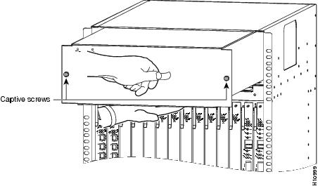
Removing the Blower Assembly
Caution
To remove the blower assembly, complete the following steps:
Step 1
Step 2
Step 3
Step 4
Step 5
Figure 2-3 Removing the Blower Assembly
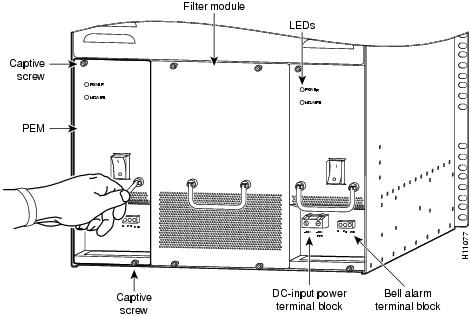
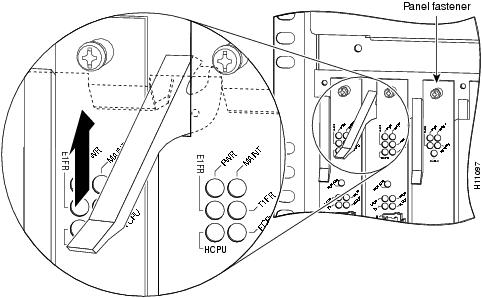
Removing the DC Power-Entry Modules
To remove the DC PEMs, complete the following steps:
Step 1
Step 2
Figure 2-4 Removing and Replacing a PEM
Step 3
This completes the PEM removal process. Proceed to "Removing Dial Shelf Cards and Dial Shelf Controller Cards."
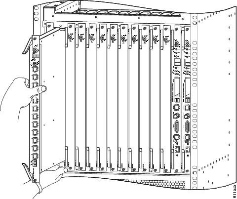
Removing Dial Shelf Cards and Dial Shelf Controller Cards
To remove the dial shelf cards and dial shelf controller cards, follow these steps:
Caution
Step 1
Step 2
Caution
Step 3
Step 4
Caution
Figure 2-5 Using the Ejector Levers
Step 5
Figure 2-6 Removing Dial Shelf Cards and Dial Shelf Controller Cards
Step 6
Step 7
Step 8
If you will be installing the dial shelf in an offset telco rack, you are now ready to install the rack-mount brackets on the chassis. Proceed to the following section, "Installing the Rack-Mount Brackets on the Chassis." If you will be installing the dial shelf in a four post rack, the dial shelf is ready to rack mount and you may proceed to the next chapter.
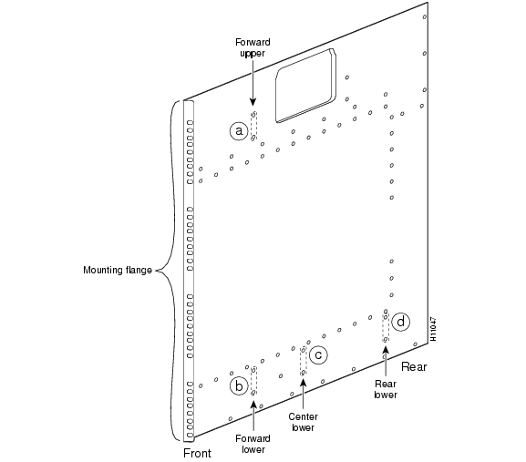
Installing the Rack-Mount Brackets on the Chassis
Bracket placement depends on the type of rack you use to install your access server. This section describes both a 4-post rack installation and a telco rack installation.
Threaded holes on the chassis sides are strategically located to position and mount bracket hardware. The dial shelf also has a mounting flange in front for flush-front mounting. If you are mounting the dial shelf in a 4-post rack, you have the option of using two brackets (one on each side) placed toward the lower rear of the chassis (see , position d) to support the chassis in the back. If you are mounting the dial shelf in a telco rack, you need to offset the dial shelf 5 in. beyond the rack center post and use six brackets (three on each side) at positions a, b, and c (See ).
Figure 2-7 Dial Shelf Bracket Mounting Hole Positions
If you are installing your access server in a telco rack, proceed to the following section, "Mounting Forward Brackets for an Offset Telco Rack Installation."
If you are installing your access server in a 4-post rack, you do not need to install brackets on the chassis front; use the permanent metal flanges on the chassis front to install the dial shelf in the rack. (See .) Proceed to the ""Installing the Dial Shelf in the Rack" section on page 3-6.
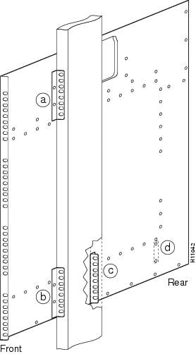
Mounting Forward Brackets for an Offset Telco Rack Installation
To install the forward rack-mount brackets on the dial shelf for an offset telco rack-mount configuration, complete the following steps:
Step 1
Step 2
Step 3
Step 4
Step 5
Step 6
Figure 2-8 Positioning the Rack-Mount Brackets for an Offset Telco Rack Installation
Review the remaining sections regarding safety and special rack-mounting considerations, and then proceed to the next chapter, "Installing the Cisco AS5800."
Plant Wiring
The following are guidelines for setting up the plant wiring and cabling at your site. When planning the location of the new system, consider the distance limitations for signaling, EMI, and connector compatibility, as described in the following sections.
Interference Considerations
When wires are run for any significant distance in an electromagnetic field, interference can occur. This fact has two implications for the construction of plant wiring:
•
•
Note
If you use twisted-pair cable in your plant wiring with a good distribution of grounding conductors, the plant wiring is unlikely to emit radio interference. If you exceed the recommended distances, use a high-quality twisted-pair cable with one ground conductor for each data signal, when applicable.
If wires exceed recommended distances, or if wires pass between buildings, give special consideration to the effect of a lightning strike in your vicinity. The electromagnetic pulse caused by lightning or other high-energy phenomena can easily couple enough energy into unshielded conductors to destroy electronic devices. If such problems have occurred in the past, you may want to consult experts in electrical surge suppression and shielding.
Distance Limitations and Interface Specifications
The size of your network and the distances between connections depend on signal type and speed and on transmission media (the type of cabling used to transmit the signals). For example, standard coaxial cable has a greater channel capacity than twisted-pair cable. The distance and rate limits in the following descriptions are the IEEE recommended maximum speeds and distances for signaling; however, you can usually get good results at speeds and distances far greater than these. For example, the recommended maximum rate for V.35 is 2 Mbps, but it is commonly used at 4 Mbps without any problems. If you understand the electrical problems that might arise and can compensate for them, you should get good results with rates and distances greater than those shown here; however, do so at your own risk.
Note
When preparing your site for network connections to the access server, you should consider the following:
•
•
•
•
•
Before installing the access server, have all additional external equipment and cables noted in the documentation that ships with each component on hand. For ordering information, contact a customer service representative.
Safety Recommendations
This section provides safety guidelines to help you avoid injury to yourself and avoid damage to the equipment. The following safety guidelines are recommended when working with any equipment that connects to electrical power or telephone wiring:
•
•
•
•
•
•
•
•
•
•
Warning
Maintaining Safety with Electricity
The Cisco 5814 dial shelf cards, dial shelf controller cards, and power supplies are designed to be removed and replaced while the system is operating, without causing damage to the system.
When working with the Cisco 7206 router shelf, however, you must power down the system before removing or replacing the I/O controller and network processing engine. For more information, refer to the Cisco 7200 Series Installation and Configuration Guide that shipped with your Cisco 7206 router shelf.
Warning
Follow these basic guidelines when working with any electrical equipment:
•
Warning
•
In addition, use the guidelines that follow when working with any equipment that is disconnected from a power source, but still connected to telephone wiring or other network cabling.
•
•
•
•
Preventing Electrostatic Discharge Damage
Electrostatic discharge (ESD) damage, which occurs when electronic cards or components are improperly handled, can result in complete or intermittent system failures. The access server components include printed circuit boards that are fixed in metal carriers. These metal carriers provide electromagnetic interference (EMI) shielding, connectors, ejector levers, or handles to protect against ESD. Although each carrier is designed to protect the boards, an antistatic strap should be used. Remember to handle the carriers by the ejector levers, handles, and carrier edges only; never touch the circuitry or connector pins.
Caution
The following are guidelines for preventing ESD damage:
•
•
•
Caution
Rack-Mounting Considerations
In a typical rack-mount configuration, you mount both the dial shelf and the router shelf together in a rack, with the dial shelf mounted below the router shelf. We do not recommend that you separate the dial shelf from the router shelf when configuring the hardware for this system; however, a 20-ft. interconnect cable is available if you need to install the router shelf in an adjacent rack. If you are using AC-input power, you mount the AC-input power shelf below the dial shelf.
There is no clearance requirement for mounting the router shelf directly above the dial shelf; however, if you install anything other than a Cisco 7206 router shelf above the dial shelf, follow the appropriate clearance requirements for the unit you install.
You can stack two access servers in a single rack; however, you must leave a minimum clearance of one rack unit between the two systems.
You must install the AC-input power shelf one rack unit, 1.75 in. (4.28 cm) below the dial shelf to accommodate the DC power cables, the monitor cable, the grounding cable, and the required safety cover.
Note
Some equipment racks provide a power strip along the length of one of the mounting strips. If your rack has a power strip, consider the position of the strip when planning fastener points to ensure that you will be able to slide dial shelf cards and dial shelf controller cards straight out of their respective slots. If the power strip does impair a rack-mount installation, remove the power strip before installing the dial shelf in the rack, then replace it after the dial shelf is installed.
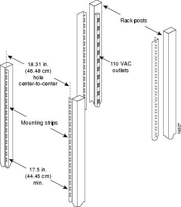
Figure 2-9 shows a typical 19-in. 4-post equipment rack with a power strip along one of the back posts.
Figure 2-9 Typical 19-Inch Equipment Rack Posts and Mounting Strips
To use the rack-mounting hardware provided with your Cisco 5814 dial shelf, consider the following guidelines:
•
•
•
When planning your rack installation, consider the following guidelines:
•
•
Caution
•
•
Warning
•
•
•
•
•
•
Warning
•
Warning
•
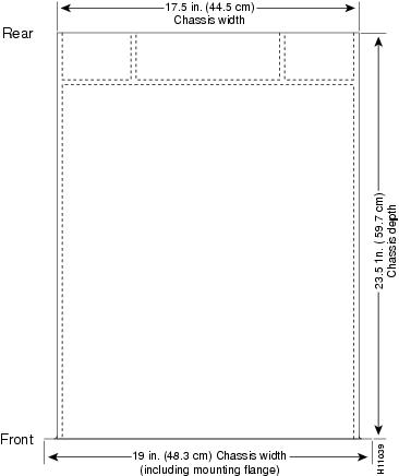
Figure 2-10 Cisco 5814 Footprint and Outer Dimensions
Caution
Caution
You are now ready to install the dial shelf in the rack. Proceed to the "Installing the Dial Shelf in the Rack" section on page 3-6.
Site Specifications
lists the operating and nonoperating environmental site requirements. The following ranges are those within which the access server will continue to operate; however, a measurement that is approaching the minimum or maximum of a range indicates a potential problem. You can maintain normal operation by anticipating and correcting environmental anomalies before they approach the maximum operating range.
Airflow to cool the access server is from front to back in the dial shelf chassis and from right to left in the router shelf chassis (when viewing the router from the front). Adhere to all spacing requirements for proper airflow maintenance.
Preventive Site Configuration: Maintaining Normal Operation
Planning a proper location for the access server and the layout of your equipment rack or wiring closet are essential for successful system operation. Equipment placed too close together or ventilated inadequately can cause system overtemperature conditions. In addition, chassis panels made inaccessible by poor equipment placement impair system maintenance.
Follow these precautions and recommendations when planning power connections to the Cisco AS5800:
•
•