Feedback
Table Of Contents
Connecting to an AC Power Source
Mount the Cables on the AC Power Supply
Installing the Power Shelf in the Rack
Installing the Dial Shelf in the Rack
Telco Rack—Rear Bracket Installation
4-Post Rack—Rear Bracket Installation
Replacing the Dial Shelf Components
Replacing the Power-Entry Modules
Replacing the Dial Shelf Cards and Dial Shelf Controller Card
Connecting Cables to the Dial Shelf
Connecting the AC Power Cables
Grounding the AC-Input Power Shelf to the Dial Shelf
Connecting the DC Power Cables
Installing the Safety Cover on the Standard Power Shelf
Connecting to a DC Power Source
Rack-Mounting the Router Shelf
Connecting the Dial Shelf to the Router Shelf
Connecting Router Shelf Port Adapter Cables
Connecting to the Router Shelf Console and Auxiliary Ports
Installing the Cisco AS5800
This chapter explains the procedures for installing the access server. Installation involves the following tasks:
1
Connecting cables to the AC power supply (AC installs only)
1
2
3
4
5
6
7
Estimated time to install the access server hardware is between 2 and 3 hours.
Note
This chapter assumes that you are installing the access server manually. If you have access to a forklift or hydraulic equipment during the installation, you can omit certain steps, which are specified later in this chapter.
Connecting to an AC Power Source
If your site has access to an AC power source only, you need to install the optional AC-input power shelf (DS58-PWR-2AC) to convert to DC-input power for the dial shelf.
AC-input power is accepted using a separate, self-contained AC-input power shelf, which converts AC-input power to DC-output for use by the DC-powered dial shelf. The AC-input is supplied by two AC power cables (CAB-DS-AC=, other options available), converted to -48V DC-output power for the dial shelf PEMs using two AC-to-DC power cables (DS5800-CAB-ACDC=) supplied by Cisco.
The AC-input power shelf is an optional component of the Cisco AS5800 and is used to convert AC-input power into DC-output power for the DC-powered Cisco 5814 dial shelf. The AC-input power shelf contains two AC-input power supplies.
This section explains how to attach the power cables and rack-mount the AC-input power shelf. For detailed cabling specification tables, refer to Appendix A, "Cisco AS5800 Specifications."
Parts Required
You need the following tools and parts to rack-mount the power shelf:
•
•
•
•
•
•
•
•
•
•
•
•
•
To connect the power cables and power up the system, proceed to the following section "Connecting the AC Power Cables."
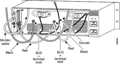
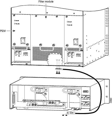
Mount the Cables on the AC Power Supply
It is possible to mount the cables on the AC power supply after it has been rack-mounted, but given the limited space in and around many equipment racks, we recommend that you mount the cables before rack-mounting the AC power supply. shows cables mounted on a standard AC power supply, but the process is the same for the enhanced power supply. For a picture of the rear of the enhanced power supply, see Figure 1-17. To mount the AC power supply cables:
Step 1
Step 2
Step 3
Step 4
Step 5
Step 6
Step 7
Figure 3-1 Cables Mounted on the Rear of the AC Power Shelf
Installing the Power Shelf in the Rack
You install the power shelf in the rack by securing the permanent mounting flanges to two posts or mounting strips in the rack using the slotted mounting screws provided. Because the mounting flanges support the weight of the entire power shelf, be sure to use at least two slotted screws per mounting flange.
Note
Caution
Caution
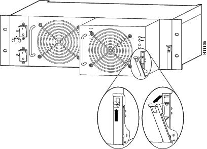
To remove a standard power supply, follow these steps:
Caution
Step 1
Step 2
Step 3
Figure 3-2 Removing and Replacing a Power Supply
Step 4
Step 5
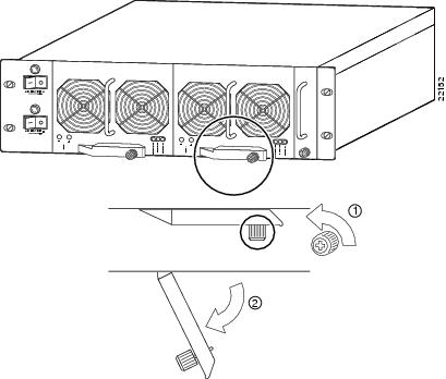
To remove a power supply for the enhanced AC-input power shelf, follow these steps:
Caution
Step 1
Step 2
Step 3
Figure 3-3 Removing and Replacing an Enhanced Shelf Power Supply
Step 4
Step 5
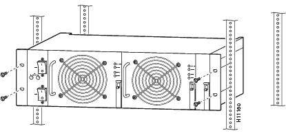
To install the power shelf in the rack, follow these steps:
Step 1
Step 2
Step 3
Step 4
Step 5
Step 6
(a)
(b)
(c)
Figure 3-4 illustrates the standard AC-input power shelf installed in a 4-post rack.
Figure 3-4 Installing the AC-Input Power Shelf in a 4-Post Rack
Installing the Dial Shelf in the Rack
One person can not install the dial shelf chassis in the rack unassisted. Two or preferably three people will be needed.
To secure the rack-mount brackets to the posts or mounting strips in the rack, you must use the slotted mounting screws provided. Because the brackets support the entire weight of the chassis, be sure to use at least two slotted screws per bracket.
Be sure you have the dial shelf prepped as described in the previous chapter before installing it in the rack. To install the dial shelf chassis in the rack, complete the following steps:
Tips
Step 1
Step 2
Note
Step 3
Warning
Step 4
Figure 3-5 Mounting Support Brackets for the Cisco AS5800
Note
Step 5
To complete the dial shelf rack installation, mount the rear set of brackets to the chassis. Proceed to the following section "Mounting the Rear Brackets."
Mounting the Rear Brackets
This section explains how to mount the rear brackets for telco and 4-post rack installations.
Note
Telco Rack—Rear Bracket Installation
For a telco rack-mount installation, mount the rear bracket as follows:
Step 1
Step 2
Step 3
Step 4
Step 5
Step 6
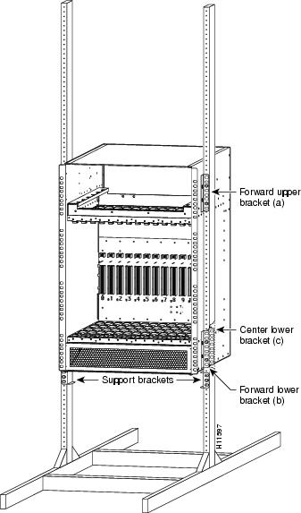
shows a dial shelf installed in a telco rack. The bracket positions labeled a, b, and c correspond to , positions a, b, and c.
Figure 3-6 Cisco 5814 Dial Shelf Installed in a Telco Rack
This completes the dial shelf rack-mounting procedures for a telco rack. Proceed to the section "Replacing the Dial Shelf Components."
4-Post Rack—Rear Bracket Installation
For a 4-post rack-mount installation, mount the optional rear brackets to the sides of the chassis as follows:
Step 1
Step 2
Step 3
Step 4
Step 5
Step 6
Step 7
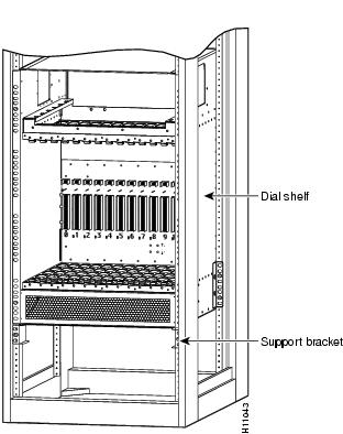
Figure 3-7 Cisco 5814 Dial Shelf Installed in a 4-Post Rack
This completes the dial shelf rack-mounting procedures for a 4-post rack. Proceed to the following section "Replacing the Dial Shelf Components."
Replacing the Dial Shelf Components
This section contains instructions for replacing the dial shelf components.
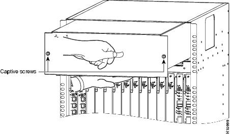
Replacing the Blower Assembly
Replace the blower module in the dial shelf as follows:
Caution
Step 1
Figure 3-8 Replacing the Blower Assembly
Step 2
Step 3
Step 4
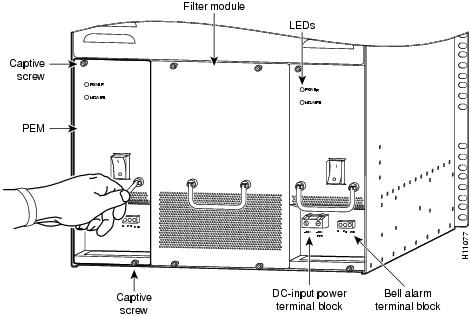
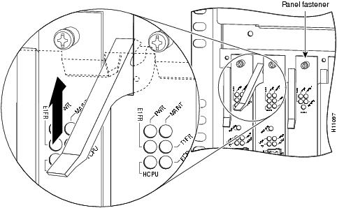
Replacing the Power-Entry Modules
To reinstall the PEMs, complete the following steps. (Refer to to locate the PEMs in the dial shelf.)
Step 1
Step 2
Step 3
Step 4
Step 5
Figure 3-9 Replacing a PEM
This completes the procedure for replacing a PEM in the dial shelf.
Replacing the Dial Shelf Cards and Dial Shelf Controller Card
Replace the trunk cards, modem cards, and dial shelf controller cards in the chassis as follows:
Timesaver
If you did not note the original card configuration, replace the cards in the dial shelf slots, which are numbered from left to right, as follows:
•
•
•
slot 12 or slot 13.
Caution
Step 1
Caution
Step 2
Step 3
Figure 3-10 Using the Ejector Levers
Step 4
Caution
Step 5
Caution
Step 6
Caution
Step 7
Caution
Connecting Cables to the Dial Shelf
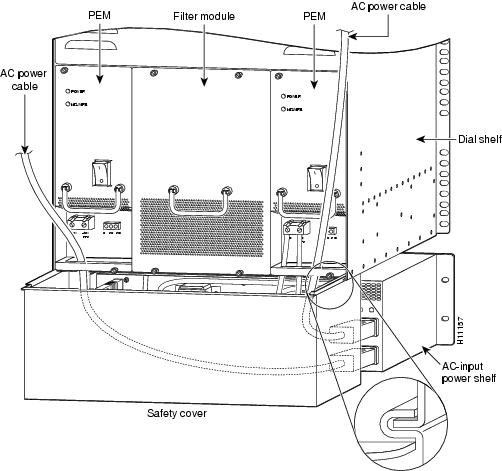
Once the dial shelf has been rack-mounted and all components have been reinstalled into the dial shelf, DC power connections from a DC source or AC-input power shelf can be connected to the dial shelf. The monitor connection from an AC-input power shelf should also be connected at this stage. The following sections assume the use of the optional AC-input power shelf. If your installation will use a DC power source, see the "Connecting to a DC Power Source" section.
Connecting the AC Power Cables
You need to connect all cables between the AC-input power shelf and the dial shelf before you connect the power shelf to your AC power source. You also need to install the provided electrical connection safety cover at the rear of the power shelf before you power up the system. For detailed cabling specification tables, refer to Appendix A, "Cisco AS5800 Specifications."
Warning
Grounding the AC-Input Power Shelf to the Dial Shelf
For detailed cabling specification information, refer to Appendix A, "Cisco AS5800 Specifications." To attach the ground cable between the AC-input power shelf and the dial shelf, complete the following steps:
Step 1
Step 2
Step 3
Figure 3-11 Attaching the Ground Wire to a Standard Power Shelf
Figure 3-12 Attaching the Ground Wire to an Enhanced Power Shelf
This completes the ground cable installation.
Connecting the DC Power Cables
For detailed cabling specification information, refer to Appendix A, "Cisco AS5800 Specifications." To connect the DC interconnect power cables, complete the following steps:
Step 1
Step 2
Step 3
Figure 3-13 Connecting the DC-Interconnect Cables
Step 4
Note
This completes the DC power cabling installation. You must now connect the monitor cable from the AC-input power shelf to the dial shelf filter module.
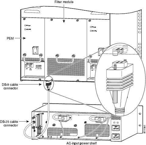
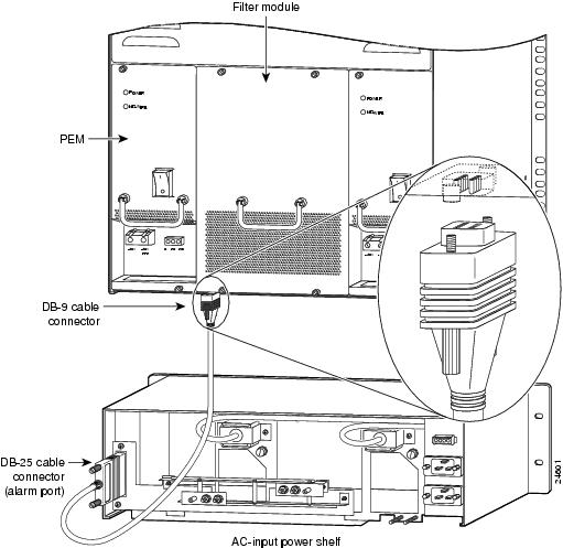
Connecting the Monitor Cable
For detailed cabling specification information, refer to Appendix A, "Cisco AS5800 Specifications." To connect the monitor cable, complete the following steps:
Step 1
Step 2
Figure 3-14 Connecting the Monitor Cable
Figure 3-15 Connecting the Monitor Cable to an Enhanced Power Shelf
This completes the monitor cable installation. You must now connect the AC-input power cords.
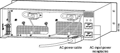
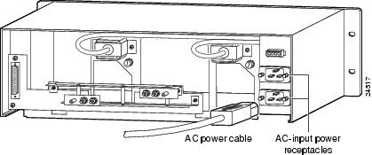
Connecting the AC Power Cords
For detailed cabling specification information, refer to Appendix A, "Cisco AS5800 Specifications." To connect the AC power cords, complete the following steps:
Step 1
Step 2
Step 3
Note
Caution
Figure 3-16 Connecting the AC Power Cords to a Standard Power Shelf
Figure 3-17 Connecting the AC Power Cords to an Enhanced Power Shelf
This completes the AC power cord installation.
Installing the Safety Cover on the Standard Power Shelf
For safety reasons, you must install the metal safety cover that shipped with your standard AC-input power shelf before you power up the system. The safety cover shields the power connections from possible short circuit and protects you from electrical shock.
Note
To install the safety cover, follow these steps:
Step 1
Step 2
Caution
Warning
Step 3
Note
Caution
Figure 3-18 Installing the Safety Cover to a Standard Power Shelf
Connecting to a DC Power Source
The following sections are for installations using a direct DC power source, without an AC-input power shelf.
Grounding the Dial Shelf
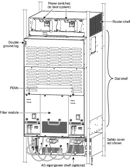
The Cisco 5814 dial shelf ships with a double ground lug attached to two pemnuts in the upper left corner on the rear of the dial shelf chassis. For detailed cabling specification information, refer to Appendix A, "Cisco AS5800 Specifications." To ground the dial shelf, follow these steps:
Warning
Warning
Step 1
Figure 3-19 Cisco AS5800—Rear View
Step 2
Step 3
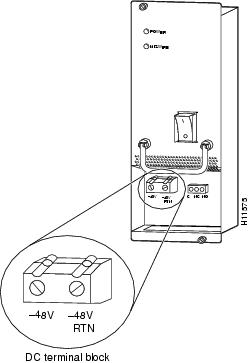
Connecting DC Power Cables
If your site has access to a DC power source, you need to provide your own DC power cables. In the United States you need to use 6 AWG stranded or solid copper wire; elsewhere use 16 mm2 solid or 10 mm2 stranded copper wire.
Complete the following cabling instructions:
Step 1
Step 2
Step 3
Figure 3-20 DC Terminal Block on the PEM
Step 4
Step 5
Note
This completes the procedure for installing the dial shelf in a rack. You are now ready to install the Cisco 7206 router shelf in the equipment rack.
Rack-Mounting the Router Shelf
The router shelf is intended to be rack-mounted above the dial shelf in the same rack; however, you can rack-mount the router shelf in an adjacent rack. The interconnect cable supplied by Cisco, which provides the physical connection between the router shelf and the dial shelf, is available in 6-ft or 20-ft lengths.
There is no clearance requirement for mounting the router shelf directly above the dial shelf. Use the rack-mounting brackets and cable-management kit that shipped with the Cisco 7206 router shelf to install the router in the rack.
Note
Note
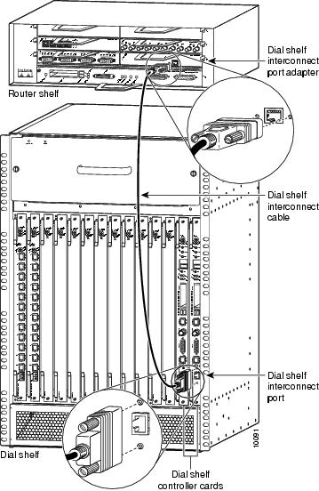
Connecting the Dial Shelf to the Router Shelf
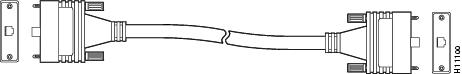
The Cisco 7206 router shelf contains a dial shelf interconnect port adapter with a single RJ-45 receptacle, which is used to connect the router shelf to the Cisco 5814 dial shelf. The interconnect port adapter installs in any 7206 router shelf port adapter slot and connects directly to the Cisco 5814 dial shelf controller card using a single full-duplex cable.
The cable used for this connection is available only from Cisco Systems. It is customized with shielding to decrease electromagnetic interference (EMI) emissions, and jackscrews to secure the connection. You must use this specially designed cable, which shipped with your interconnect port adapter, to connect the dial shelf to the router shelf. For detailed cabling specification information, refer to Appendix A, "Cisco AS5800 Specifications." If the cable was not shipped, contact CCO as described in the"Cisco Connection Online" section.
shows the dial shelf interconnect cable with jackscrew connectors.
Figure 3-21 Dial Shelf Interconnect Cable
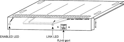
shows the RJ-45 receptacle on the dial shelf interconnect port adapter.
Figure 3-22 Dial Shelf Interconnect Port Adapter Front Panel
To connect the dial shelf interconnect cable, follow these steps:
Caution
Warning
Warning
Step 1
Step 2
Step 3
Step 4
Step 5
Caution
Figure 3-23 Connecting the Dial Shelf Interconnect Cable
Connecting Router Shelf Port Adapter Cables
Egress connections to LANs and WANs are made through the host Cisco 7206 router shelf. Using port adapters, the router shelf supports interfaces such as FDDI, HSSI, Fast Ethernet, and ATM. Each interface port adapter is shipped with separate configuration instructions and cable information.
For example, if you install a Fast Ethernet port adapter in the Cisco 7206 router shelf, refer to the configuration note PA-FE-TX and PA-FE-FX Fast Ethernet 100BASE-T Port Adapter Installation and Configuration (Part Number 78-2659-xx) that shipped with your Fast Ethernet port adapter. This document is also available in the Documentation CD-ROM and on Cisco Connection Online (CCO).
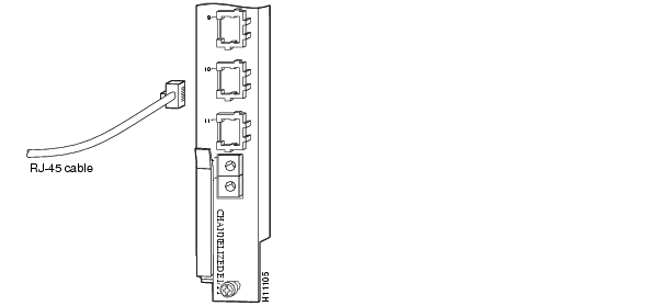
Connecting Trunk Card Cables
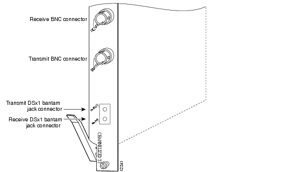
The trunk card provides 12 RJ-45 receptacles for channelized E1 or T1 lines, or BNC connectors for T3 trunk lines. To connect T1 or E1 trunk lines, follow these steps:
Warning
Warning
Warning
Warning
Step 1
Step 2
Step 3
For more information about trunk cables and trunk cards, refer to the Cisco AS5800 Universal Access Server Dial Shelf Card Guide.
Warning
Warning
Figure 3-24 Connecting the CT1 and CE1 Trunk Card RJ-45 Cables
To connect the T3 lines, follow these steps:
Step 1
Step 2
Figure 3-25 CT3 Trunk Card BNC Cable Connections
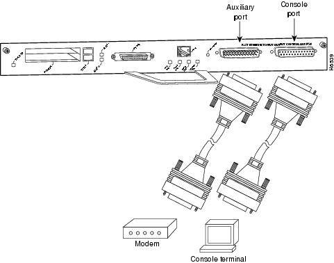
Connecting to the Router Shelf Console and Auxiliary Ports
A DCE-mode console port and a DTE-mode auxiliary port are located on the router shelf I/O controller. The console port is a DB-25 receptacle for connecting a data terminal, which you use to run the initial setup script and bring up the Cisco AS5800. The auxiliary port is a DB-25 plug for connecting a modem or other DCE device (such as a CSU/DSU or other router) to the router shelf. (See .)
Note
Before connecting a terminal to the console port, configure the terminal to match the router console port as follows: 9600 baud, 8 data bits, no parity, 2 stop bits (9600 8N2). You need an EIA/TIA-232 DCE console cable to connect the terminal to the console port. After you establish normal router operation, you can disconnect the terminal. While both the router shelf and the dial shelf have console ports, functions for both shelves are available from the router console port.
You must supply your own interface cable between the auxiliary port and the equipment you are connecting. Refer to the Cisco 7206 Installation and Configuration Guide that shipped with your router shelf for console and auxiliary port pinouts.
Figure 3-26 Connecting the Router Shelf Console and Auxiliary Ports
This completes the procedures for installing and cabling your Cisco AS5800. To start the access server, proceed to Chapter 4, "Powering On the Cisco AS5800 and Observing Initial Startup Conditions."