-
Cisco AS5300 Software Configuration Guide
-
About This Guide
-
Chap 1: First-Time Configuration
-
Chap 2: Using Cisco IOS Software
-
Chap 3: Basic Configuration
-
Chap 4: Access Service Security
-
App A: Managing Modems
-
App B: ROM Monitor
-
App C: Using Setup on Cisco IOS Releases 11.2 or 11.3(2)T
-
App D: Upgrade VoIP Software
-
Update to AS5300 Installation and Software Configuration Guides
-
 Feedback
Table Of Contents
First-Time Configuration
This chapter describes how to power ON the Cisco AS5300 universal access server and configure it using the prompt-driven setup script (also called the System Configuration dialog). The following sections are included:
If you prefer to configure the access server manually, proceed to the next chapter "" to familiarize yourself with the command-line interface (CLI) and then proceed to the following chapter "Basic Configuration" for step-by-step instructions.
Using the Setup Script
The setup script in this section uses the latest release version of Cisco IOS software.
Note
If your system is running Cisco IOS Release 11.2 or 11.3(2)T, see the appendix "Using Setup on Cisco IOS Releases 11.2 or 11.3(2)T" for intructions and screen displays.
Getting Started
Before you power on the access server and begin to use the setup script in the System Configuration dialog, make sure you have already connected the cables to the access server and configured your PC terminal emulation program for 9600 baud, 8 data bits, no parity, and 2 stop bits. All configuration will be performed from your PC terminal emulation program window.
The prompts and resulting messages vary depending on your responses. For most configurations, you can press Enter to accept the default entries displayed in square ([]) brackets.
Note
To use the setup script take the following steps:
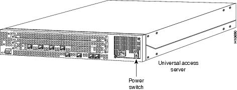
Step 1
Figure 1-1 Power Switch Location
Messages will begin to appear in your terminal emulation program window.
CautionDo not press any keys on the keyboard until the messages stop. Any keys pressed during this time will be interpreted as the first command typed when the messages stop, which might cause you to power cycle the access server and start over. It will take a few minutes for the messages to stop.
The messages look similar to the following:
Note
System Bootstrap, Version 12.0(3)T, RELEASED SOFTWARECopyright (c) 1994-1998 by cisco Systems, Inc.AS5300 processor with 32768 Kbytes of main memoryrommon 3 > b flash:2:program load complete, entry point: 0x80008000, size: 0x5d7b5cSelf decompressing the image : ################################################################################# ###################]Restricted Rights LegendUse, duplication, or disclosure by the Government issubject to restrictions as set forth in subparagraph(c) of the Commercial Computer Software - RestrictedRights clause at FAR sec. 52.227-19 and subparagraph(c) (1) (ii) of the Rights in Technical Data and ComputerSoftware clause at DFARS sec. 252.227-7013.cisco Systems, Inc.170 West Tasman DriveSan Jose, California 95134-1706Cisco Internetwork Operating System SoftwareIOS (tm) 5300 Software (C5300-JS-M), Released Version 12.0(19981001:221340) [ayeh-wk_0_6_0 100]Copyright (c) 1986-1998 by cisco Systems, Inc.Compiled Thu 01-Oct-98 15:13 by ayehImage text-base: 0x600088E8, data-base: 0x609F6000cisco AS5300 (R4K) processor (revision A.14) with 32768K/16384K bytes of memory.Processor board ID 05433592R4700 processor, Implementation 33, Revision 1.0 (512KB Level 2 Cache)Bridging software.X.25 software, Version 3.0.0.SuperLAT software copyright 1990 by Meridian Technology Corp).TN3270 Emulation software.Primary Rate ISDN software, Version 1.1.Backplane revision 2Manufacture Cookie Info:EEPROM Type 0x0001, EEPROM Version 0x01, Board ID 0x30,Board Hardware Version 1.0, Item Number 73-2414-2,Board Revision 3, Serial Number 05433592,PLD/ISP Version 255.255, Invalid Date code.1 Ethernet/IEEE 802.3 interface(s)1 FastEthernet/IEEE 802.3 interface(s)4 Serial network interface(s)120 terminal line(s)4 Channelized T1/PRI port(s)128K bytes of non-volatile configuration memory.8192K bytes of processor board System flash partition 1 (Read/Write)8192K bytes of processor board System flash partition 2 (Read/Write)4096K bytes of processor board Boot flash (Read/Write)--- System Configuration Dialog ---Step 2
Continue with configuration dialog? [yes/no]: yesAt any point you may enter a question mark '?' for help.Use ctrl-c to abort configuration dialog at any prompt.Default settings are in square brackets '[]'.Step 3
Basic management setup configures only enough connectivityfor management of the system, extended setup will ask youto configure each interface on the systemWould you like to enter basic management setup? [yes/no]: noStep 4
First, would you like to see the current interface summary? [yes]:Any interface listed with OK? value "NO" does not have a valid configurationInterface IP-Address OK? Method Status ProtocolEthernet0 171.69.90.18 YES NVRAM up downFastEthernet0 unassigned YES unset administratively down downGroup-Async1 171.69.90.18 YES unset down downSerial0 unassigned YES unset administratively down downSerial1 unassigned YES unset administratively down downSerial2 unassigned YES unset administratively down downSerial3 unassigned YES unset administratively down downSerial0:0 unassigned YES unset down downSerial0:1 unassigned YES unset down down...Serial3:21 unassigned YES unset down downSerial3:22 unassigned YES unset down downSerial3:23 171.69.90.18 YES unset down downStep 5
Configuring global parameters:Enter host name [Router]: 5300The enable secret is a password used to protect access to privileged EXEC and configuration modes. This password, after entered, becomes encrypted in the configuration.Step 6
Enter enable secret: labThe enable password is used when you do not specify an enable secret password, with some older software versions, and some boot images.Step 7
Enter enable password: guessmeThe virtual terminal password is used to protect access to the router over a network interface.Step 8
Enter virtual terminal password: guessagainStep 9
Configure System Management? [yes/no]: yesShelf-id [0]:System Controller IP address: 172.87.98.01System Controller password: sctestStep 10
Configure SNMP Network Management? [no]: yesCommunity string [public]:Configure LAT? [yes]:Configure AppleTalk? [no]: yesMultizone networks? [no]: yesConfigure DECnet? [no]:Configure IP? [no]:Configure IGRP routing? [yes]:Your IGRP autonomous system number [1]: 15
Note
Configure CLNS? [no]:Configure IPX? [no]: yesConfigure Vines? [no]:Configure XNS? [no]:Configure Apollo? [no]:Step 11
Async lines accept incoming modems calls. If you will have users dialing in via
modems, configure these lines.
Configure Async lines? [yes]:
Note
Async line speed [115200]:Will you be using the modems for inbound dialing? [yes]:
Note
Would you like to put all async interfaces in a group and configure them all at
one time ? [yes]
Note
Allow dial-in users to choose a static IP address? [no]:Configure for TCP header compression? [yes]:Configure for routing updates on async links? [no]:
Note
Enter the starting address of IP local pool? [X.X.X.X]: 172.20.30.40Enter the ending address of IP local pool? [X.X.X.X]: 172.20.30.88You can configure a test user to verify that your dial-up service is working properly.What is the username of the test user? [user]:What is the password of the test user? [passwd]:Will you be using the modems for outbound dialing? [no]:Configure for Async IPX? [yes]: noConfigure for Appletalk Remote Access (ARA)? [no]: yesAppleTalk Network for ARAP clients [1]:Zone name for ARAP clients [ARA Dialins]:Allow ARAP "Guest" logins? [yes/no]: yesStep 12
Do you want to configure ISDN switch type? [yes]:The following ISDN switch types are available:[a] primary-4ess[b] primary-5ess[c] primary-dms100[d] primary-net5[e] primary-ntt[f] primary-ts014Enter the switch type [b]:Step 13
Next, you will be prompted to configure controllers.These controllers enable users to dial in via ISDN or analog modems.Do you intend to allow users to dial in? [yes]:There are 8 controllers on this access server. If you want to usethe full capacity of the access server configure all controllers.Controller T1 0,1,..etc in software corresponds to Port 0,1,..etcon the back of the access server.PRI configuration can be configured to controllers all at oncebased on your PRI controllers selection. Where as CAS configurationwill be configured individually for each controller.Step 14
Enter # of controllers, you will be using for PRI configuration [8]:Configuring controller parameters:Step 15
Configuring controller T1 2:Will you be using CT1 (robbed bit signaling) on this controller? [yes]:Step 16
The following framing types are available: esf | sfEnter the framing type [esf]:Step 17
The following linecode types are available: ami | b8zsEnter the line code type [b8zs]:Step 18
The following line signaling types are available:[a] e&m-fgb[b] e&m-fgd[c] e&m-immediate-start[d] fxs-ground-start[e] fxs-loop-start[f] sas-ground-start[g] sas-loop-startEnter the line signaling type [a]:Step 19
The following tone signaling types are available: dtmf | mfEnter the tone signal type [dtmf]:Step 20
Do you want to provision DNIS address information? [yes]:Step 21
Step 22
Configuring interface parameters:Do you want to configure Ethernet0 interface? [no]: yesConfigure IP on this interface? [no]: yesIP address for this interface: 172.21.40.10Subnet mask for this interface [255.0.0.0] :Class B network is 172.21.0.0, 16 subnet bits; mask is /16Configure LAT on this interface? [no]:Configure AppleTalk on this interface? [no]:Configure IPX on this interface? [no]:Step 23
Do you want to configure FastEthernet0 interface? [yes]: yes
Note
Operate in full-duplex mode? [no]: yesOperate at 100 Mbps speed? [yes]:Configure IP on this interface? [yes]:IP address for this interface [X.X.X.X]: 172.22.50.10Subnet mask for this interface [255.255.0.0] :Class B network is 172.22.0.0, 16 subnet bits; mask is /16Configure LAT on this interface? [no]:Configure AppleTalk on this interface? [no]:Configure IPX on this interface? [no]:Step 24
Do you want to configure Serial0 interface? [no]: yes
Note
Configure IP on this interface? [no]: yesConfigure IP unnumbered on this interface? [no]:IP address for this interface: 173.20.30.40Subnet mask for this interface [255.255.0.0] :Class B network is 173.20.0.0, 16 subnet bits; mask is /16Configure LAT on this interface? [no]:Configure AppleTalk on this interface? [no]:Configure IPX on this interface? [no]:Step 25
Step 26
Do you want to configure Serial0:23 (PRI D-channel) interface? [no]: yesConfigure IP on this interface? [no]: yesConfigure IP unnumbered on this interface? [no]:IP address for this interface: 173.20.30.40Subnet mask for this interface [255.255.0.0] :Class B network is 173.20.0.0, 16 subnet bits; mask is /16Configure LAT on this interface? [no]:Configure AppleTalk on this interface? [no]:Configure IPX on this interface? [no]:Step 27
After you complete the configuration script, messages similar to the following appear.
The following configuration command script was created:hostname 5300enable secret 5 $1$WVLB$YD0zbQsu3nqZh/bnN2fwX0enable password guessmeline vty 0 4password guessagainsyscon shelf-id 0syscon address 172.87.98.1 sctestsnmp-server community public!appletalk routingno decnet routingno ip routingno clns routingipx routingno vines routingno xns routingno apollo routing!line 1 120speed 115200flowcontrol hardwarelogin localautoselect during-loginautoselect pppmodem dialinip local pool setup_pool 172.20.30.40 172.20.30.88!username user password passwd!arap network 1 ARA Dialinsline 1 120arap enableautoselect arap!! Turn off IPX to prevent network conflicts.interface Ethernet0no ipx networkinterface FastEthernet0no ipx networkinterface Serial0no ipx networkinterface Serial1no ipx networkinterface Serial2no ipx networkinterface Serial3no ipx networkinterface Serial0:23no ipx networkinterface Serial1:23no ipx networkinterface Serial2:23no ipx networkinterface Serial3:23no ipx network!isdn switch-type primary-5ess!controller T1 0no shutdownframing esflinecode b8zscas-group 0 timeslots 1-24 type e&m-fgb dtmf dnis!controller T1 1no shutdownframing esflinecode b8zscas-group 0 timeslots 1-24 type e&m-fgb dtmf dnis!controller T1 2no shutdownframing esflinecode b8zscas-group 0 timeslots 1-24 type e&m-fgb dtmf dnis!controller T1 3no shutdownframing esflinecode b8zscas-group 0 timeslots 1-24 type e&m-fgb dtmf dnis!controller T1 4no shutdownframing esflinecode b8zscas-group 0 timeslots 1-24 type e&m-fgb dtmf dnis!controller T1 5no shutdownframing esflinecode b8zscas-group 0 timeslots 1-24 type e&m-fgb dtmf dnis!controller T1 6no shutdownframing esflinecode b8zscas-group 0 timeslots 1-24 type e&m-fgb dtmf dnis!controller T1 7no shutdownframing esflinecode b8zscas-group 0 timeslots 1-24 type e&m-fgb dtmf dnisscheduler interval 1000line console 0logging synchronous!interface Ethernet0no shutdownip address 172.21.40.10 255.255.0.0no lat enabledno mop enabled!interface FastEthernet0duplex fullspeed 100ip address 172.22.50.10 255.255.0.0no lat enabledno mop enabled!interface Serial0no shutdownip address 173.20.30.40 255.255.0.0no lat enabledno mop enabled!interface Serial1shutdownno ip address!interface Serial2shutdownno ip address!interface Serial3shutdownno ip address!interface Serial0:23no shutdownno ip addressno lat enabledno mop enabled!interface Serial1:23no shutdownip address 173.20.30.40 255.255.0.0no lat enabledno mop enabled!interface Serial2:23no shutdownno ip addressno lat enabledno mop enabledno shutdownno ip addressno lat enabledno mop enabled!Interface Group-Async1group-range 1 120ip unnumbered FastEthernet0encapsulation pppppp authentication chap pappeer default ip address pool setup_poolip tcp header-compression passiveasync mode interactivedialer-list 1 protocol ip permitdialer-list 1 protocol ipx permit!endendStep 28
[0] Go to the IOS command prompt without saving this config.[1] Return back to the setup without saving this config.[2] Save this configuration to nvram and exit.Enter your selection [2]:Use this configuration? [yes/no]: yesBuilding configuration...Use the enabled mode 'configure' command to modify this configuration.Press RETURN to get started!%LINK-3-UPDOWN: Interface Ethernet0, changed state to up%LINK-3-UPDOWN: Interface Serial0, changed state to down%LINK-3-UPDOWN: Interface Serial1, changed state to down<Additional messages omitted.>Step 29
5300>%AT-6-ONLYROUTER: Ethernet0: AppleTalk port enabled; no neighbors found
Note
Step 30
•
5300> enablePassword: <password>5300# setup•
Where to Go Next
At this point you can proceed to:
•
•
•
http://www.cisco.com/univercd/cc/td/doc/product/access/acs_serv/5300/sw_conf/index.htm