Downloads |
 Feedback Feedback
|
Table Of Contents
Configuring a LAN with DHCP and VLANs
Verify Your DHCP Configuration
Assign a Switch Port to a VLAN
Verify Your VLAN Configuration
Configuring a LAN with DHCP and VLANs
The Cisco 870 series routers support clients on both physical LANs and virtual LANs (VLANs). The routers can use the Dynamic Host Configuration Protocol (DHCP) to enable automatic assignment of IP configurations for nodes on these networks.
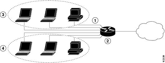
Figure 5-1 shows a typical deployment scenario with two physical LANs connected by the router and two VLANs.
Figure 5-1 Physical and Virtual LANs with DHCP Configured on the Cisco Router
Fast Ethernet LAN (with multiple networked devices)
Router and DHCP server—Cisco 870 series access router—connected to the Internet
VLAN 1
VLAN 2
DHCP
DHCP, which is described in RFC 2131, uses a client/server model for address allocation. As an administrator, you can configure your Cisco 800 series router to act as a DHCP server, providing IP address assignment and other TCP/IP-oriented configuration information to your workstations. DHCP frees you from having to manually assign an IP address to each client.
When you configure a DHCP server, you must configure the server properties, policies, and DHCP options.
Note
Whenever you change server properties, you must reload the server with the configuration data from the Network Registrar database.
VLANs
The Cisco 870 series access routers support four Fast Ethernet ports on which you can configure VLANs.
VLANs enable networks to be segmented and formed into logical groups of users, regardless of the user's physical location or LAN connection.
Configuration Tasks
Perform the following tasks to configure this network scenario:
Note
Configure DHCP
Perform these steps to configure your router for DHCP operation, beginning in global configuration mode:
Configuration Example
The following configuration example shows a portion of the configuration file for the DCHP configuration described in this chapter.
ip dhcp excluded-address 192.168.9.0!ip dhcp pool dpool1import allnetwork 10.10.0.0 255.255.255.0default-router 10.10.10.10dns-server 192.168.35.2domain-name cisco.com!ip domain name smallbiz.comip name-server 192.168.11.12Verify Your DHCP Configuration
Use the following commands to view your DHCP configuration.
•
•
•
Router# show ip dhcp importAddress Pool Name: dpool1Router# show ip dhcp poolPool dpool1 :Utilization mark (high/low) : 100 / 0Subnet size (first/next) : 0 / 0Total addresses : 254Leased addresses : 0Pending event : none1 subnet is currently in the pool :Current index IP address range Leased addresses10.10.0.1 10.10.0.1 - 10.10.0.254 0Router# show ip dhcp server statisticsMemory usage 15419Address pools 1Database agents 0Automatic bindings 0Manual bindings 0Expired bindings 0Malformed messages 0Secure arp entries 0Message ReceivedBOOTREQUEST 0DHCPDISCOVER 0DHCPREQUEST 0DHCPDECLINE 0DHCPRELEASE 0DHCPINFORM 0Message SentBOOTREPLY 0DHCPOFFER 0DHCPACK 0DHCPNAK 0Router#Configure VLANs
Perform these steps to configure VLANs on your router, beginning in global configuration mode:
Step 1
vlan ?
Example:
Router# config tRouter(config)#vlan ?WORD ISL VLAN IDs 1-4094accounting VLAN accounting configurationifdescr VLAN subinterface ifDescrRouter(config)#vlanEnters VLAN configuration mode.
Step 2
ISL VLAN ID
Example:
Router(config)#vlan2Router(config-vlan)#Adds VLANs, with identifiers ranging from
1- 4094.For details about this command and additional parameters that can be set, see the Cisco IOS Switching Services Command Reference.
Step 3
exit
Example:
Router(config-vlan)#exitRouter(config)#Updates the VLAN database, propagates it throughout the administrative domain, and returns to global configuration mode.
Assign a Switch Port to a VLAN
Perform these steps to assign a switch port to a VLAN, beginning in global configuration mode:
Verify Your VLAN Configuration
Use the following commands to view your VLAN configuration.
•
•
Router# vlan databaseRouter(vlan)# showVLAN ISL Id: 1Name: defaultMedia Type: EthernetVLAN 802.10 Id: 100001State: OperationalMTU: 1500Translational Bridged VLAN: 1002Translational Bridged VLAN: 1003VLAN ISL Id: 2 Name: VLAN0002 Media Type: Ethernet VLAN 802.10 Id: 100002 State: Operational MTU: 1500VLAN ISL Id: 3 Name: red-vlan Media Type: Ethernet VLAN 802.10 Id: 100003 State: Operational MTU: 1500VLAN ISL Id: 1002Name: fddi-defaultMedia Type: FDDIVLAN 802.10 Id: 101002State: OperationalMTU: 1500Bridge Type: SRBTranslational Bridged VLAN: 1Translational Bridged VLAN: 1003VLAN ISL Id: 1003Name: token-ring-defaultMedia Type: Token RingVLAN 802.10 Id: 101003State: OperationalMTU: 1500Bridge Type: SRBRing Number: 0Bridge Number: 1Parent VLAN: 1005Maximum ARE Hop Count: 7Maximum STE Hop Count: 7Backup CRF Mode: DisabledTranslational Bridged VLAN: 1Translational Bridged VLAN: 1002VLAN ISL Id: 1004Name: fddinet-defaultMedia Type: FDDI NetVLAN 802.10 Id: 101004State: OperationalMTU: 1500Bridge Type: SRBBridge Number: 1STP Type: IBMVLAN ISL Id: 1005Name: trnet-defaultMedia Type: Token Ring NetVLAN 802.10 Id: 101005State: OperationalMTU: 1500Bridge Type: SRBBridge Number: 1STP Type: IBMRouter# show vlan-switchVLAN Name Status Ports---- -------------------------------- --------- -------------------------------1 default active Fa0, Fa1, Fa32 VLAN0002 active Fa21002 fddi-default active1003 token-ring-default active1004 fddinet-default active1005 trnet-default activeVLAN Type SAID MTU Parent RingNo BridgeNo Stp BrdgMode Trans1 Trans2---- ----- ---------- ----- ------ ------ -------- ---- -------- ------ ------1 enet 100001 1500 - - - - - 1002 10032 enet 100002 1500 - - - - - 0 01002 fddi 101002 1500 - - - - - 1 10031003 tr 101003 1500 1005 0 - - srb 1 10021004 fdnet 101004 1500 - - 1 ibm - 0 01005 trnet 101005 1500 - - 1 ibm - 0 0