Downloads |
 Feedback Feedback
|
Table Of Contents
Cisco 90-Day Limited Hardware Warranty Terms
Documents, Equipment, and Tools
Items Included with Cisco 3745 Routers
Connecting Routers to AC Power
Connecting Routers to DC Power
Connecting Routers to the Cisco Redundant Power System
WAN, LAN, and Voice Connections
Initial Configuration Using Cisco Router and Security Device Manager
Initial Configuration Using the Setup Command Facility
Initial Configuration Using the CLI (Manual Configuration)
WAN and LAN Interface Numbering
Cisco Product Security Overview
Reporting Security Problems in Cisco Products
Product Alerts and Field Notices
Obtaining Technical Assistance
Cisco Technical Support & Documentation Website
Definitions of Service Request Severity
Obtaining Additional Publications and Information
Quick Start Guide
Cisco 3745 Router
INCLUDING LICENSE AND WARRANTY1 Cisco 90-Day Limited Hardware Warranty Terms
The following are terms applicable to your hardware warranty. Your formal Warranty Statement, including the warranty applicable to Cisco software, appears in the Cisco Information Packet that accompanies your Cisco product.
Duration of Hardware Warranty: Ninety (90) Days
Replacement, Repair or Refund Procedure for Hardware: Cisco or its service center will use commercially reasonable efforts to ship a replacement part within ten (10) working days after receipt of the RMA request. Actual delivery times may vary depending on Customer location. Cisco reserves the right to refund the purchase price as its exclusive warranty remedy.
To Receive a Return Materials Authorization (RMA) Number
Please contact the party from whom you purchased the product. If you purchased the product directly from Cisco, contact your Cisco Sales and Service Representative
Complete the form below, and keep it for reference:
Product purchased from
Their telephone number
Product number and Serial number
Maintenance Contract number
Product warranty terms and other information applicable to Cisco products are available at the following URL:
http://www.cisco.com/go/warranty
Consult the above website or your Cisco Sales and Service Representative for a complete listing of Cisco products and applicable warranties.
2 Documents, Equipment, and Tools
User Documentation
All the documents described here are available online on Cisco.com. To be sure of obtaining the latest information, you should access the online documentation.
To view or print a document in its original page format, access the online document, and click on the PDF icon.
For information about accessing user documentation, see the "Where to Go Next" section.
Items Included with Cisco 3745 Routers
•
Rack-mount brackets; ground lug; power cords
•
•
•
•
•
•
•
•
Items Not Included
Individual items in this list may be required for your particular application:
•
•
•
•
3 Install Chassis
Safety Information
For safety information you need to know before working on your Cisco router, refer to the Cisco 2600 Series, Cisco 3600 Series, and Cisco 3700 Series Regulatory Compliance and Safety Information document that accompanied this device.
Note
Warning Definition
Warning
Warning
Warning
Warning
Warning
Warning
Warning
Warning
Warning
Installing the Chassis
You can set the chassis on a desktop or install it in a rack. See the applicable instructions in the following sections:
Note
Rack-Mounting the Chassis
The standard accessory kit contains brackets for mounting the chassis in a 19-inch rack. You can order an optional accessory kit with brackets and instructions for mounting the chassis in a 23- or 24-inch rack.
You can mount the chassis in the following ways:
•
•
•
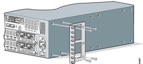
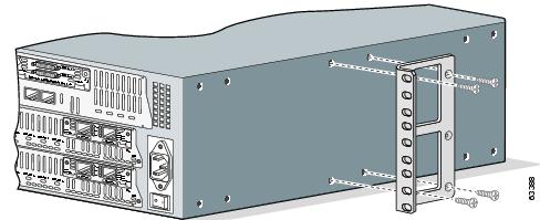
Attaching Brackets
Attach the mounting brackets to the chassis as shown in Figure 1, Figure 2, or Figure 3, using the screws provided in the bracket kit. Attach the second bracket to the opposite side of the chassis. Use a number 2 Phillips screwdriver to install the bracket screws.
Note
Figure 1 Bracket Installation—Front Panel Forward
Figure 2 Bracket Installation—Back Panel Forward
Figure 3 Bracket Installation—Back Panel Forward, Center-Mount Rack
Note
Installing the Chassis in a Rack
Install the chassis in the rack. Rack-mounting screws are not provided with the router. Use two screws for each side (supplied with the rack).
Installing on a Desktop
Caution
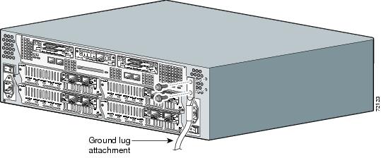
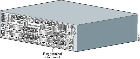
Grounding the Chassis
You must connect the chassis to a reliable earth ground; the ground wire must be installed in accordance with local electrical safety standards.
•
•
•
To connect the chassis to a reliable earth ground, perform the following steps:
Step 1
•
•
Step 2
Step 3
Step 4
Figure 4 NEBS-Compliant Chassis Ground Connection Using Ground Lug
Figure 5 Chassis Ground Connection Using Ring Terminal
4 Connect Cables
Warning
Caution
System Management Connections
The connections described in Table 1 provide system management access.
Power Connections
Warning
Note
Connecting Routers to AC Power
If your router uses AC power, connect it to a 15 A, 120 VAC (10 A, 240 VAC) circuit with overcurrent protection.
Note
Warning
Warning
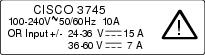
15A, 120VAC (10A, 240VAC). Statement 1005
Connecting Routers to DC Power
If your router has a DC-input power supply, follow the directions in this section for proper wiring.
Warning
20A, 60VDC. Statement 1005
Warning
DC Wiring Requirements
A Cisco 3745 router with a DC-input power supply requires copper wire for the power connections. Table 2 summarizes the wiring requirements.
Table 2 DC Wiring Requirements for Cisco 3745 Routers
Nominal 24/48 VDC1
Identified by the following printed label:
24 - 36 V, 15 A
AWG 12
(3.0 mm2)AWG 12
(3.0 mm2), minimumAmp/Tyco No. 52961 or equivalent
20 A maximum
36 - 60 V, 7 A
AWG 12 or 14
(3.0 or 2.0 mm2)AWG 12
(3.0 mm2), minimumFor AWG 12: Amp/Tyco No. 52961 or equivalent
For AWG 14: Molex No. 19099-0017 or equivalent
20 A maximum
Nominal 48 VDC2
Identified by the following printed label:
48 - 60 V, 10 A
AWG 14 or 16
(2.0 or 1.2 mm2)AWG 14
(2.0 mm2), minimumFor AWG 14 or 16: Molex No. 19099-0017 or equivalent
20 A maximum
1 The input voltage tolerance limits for nominal 24/48 V power supplies are 18 and 72 VDC.
2 The input voltage tolerance limits for nominal 48 V power supplies are 38 and 72 VDC.
Wiring Procedure for DC Input
To connect the router to a DC power source, perform the following steps:
Step 1
Warning
Tip
Step 2
Step 3
Warning
Step 4
Step 5
Warning
Warning
Caution
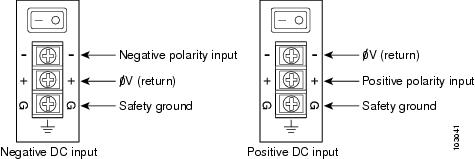
Figure 6 Terminal Block Connections for DC Input Power
Step 6
Warning
Step 7
Step 8
Step 9
Connecting Routers to the Cisco Redundant Power System
If your router uses the Cisco Redundant Power System (RPS), refer to the Cisco RPS Hardware Installation Guide for instructions about the power connections.To locate these documents, see the "Where to Go Next" section.
WAN, LAN, and Voice Connections
The connections and cables listed here are described in detail in the following documents:
•
•
•
•
For information about accessing these documents, see the "Where to Go Next" section.
Table 3 summarizes some typical WAN, LAN, and voice connections for Cisco 3745 routers.
Table 3 WAN, LAN, and Voice Connections
FastEthernet
RJ-45, yellow,
Ethernet hub or switch
Straight-through Ethernet
T1/E1 WAN
RJ-48C/CA81A, blue
T1 or E1 network
RJ-48 T1
Cisco serial
60-pin D-sub
CSU/DSU and serial network or equipment
Cisco serial transition cable that matches the signaling protocol (EIA/TIA-232, EIA/TIA-449, V.35, X.21, or EIA/TIA-530) and the serial port operating mode (DTE or DCE).1
Cisco Smart serial
Cisco Smart compact connector, blue
CSU/DSU and serial network or equipment. For WIC-2T and WIC-2A/S only
DSL
RJ-11C/CA11A, lavender
Network demarcation device for service provider's DSL interface
RJ-11
T1 digital voice
RJ-48C/CA81A, tan
Digital PBX
RJ-48 T1 cable
Analog voice FXS
RJ-11, gray
Telephone, fax
RJ-11
Analog voice FXO
RJ-11, pink
Central office, analog PBX
RJ-11
Analog voice E&M
RJ-11, brown
Analog PBX
RJ-11
BRI S/T WAN
(external NT1)RJ-48C/CA81A, red
NT1 device or private integrated network exchange (PINX)
RJ-48
BRI U WAN
(built-in NT1)RJ-49C/CA-A11, orange
ISDN network
RJ-49
CT1/PRI
T1
External T1 CSU
DB-15 T1 serial cable
CT1/PRI-CSU
T1
RJ-48C/CA81A interface
RJ-48 straight-through
CE1/PRI
E1
E1 network
DB-15 to BNC, DB-15 to DB-15, DB-15 to twinax, or DB-15 to RJ-45
56/64-kbps DSU/CSU
8-pin modular, blue
RJ-48S interface
RJ-48 straight-through
1 See the Cisco Modular Access Router Cable Specifications document for information about selecting these cables.
5 Power Up the Router
Checklist for Power-Up
You are ready to power on the Cisco router if the following steps are completed:
•
•
•
•
•
Front Panel Indicators
The following indicator LEDs provide power, activity, and status information:
•
–
–
–
–
•
–
•
–
–
–
•
–
–
–
Power-Up Procedure
To power up your Cisco router and verify that it goes through its initialization and self-test, perform this procedure. When the power-up procedure is finished, the Cisco router is ready to be configured.
Note
Step 1
Step 2
Note
Messages begin to appear in your terminal emulation program window.
Caution
You may see different startup messages:
•
yourname con0 is now availablePress RETURN to get started.See the "Initial Configuration Using Cisco Router and Security Device Manager" section to learn how to configure your router using SDM or to learn how to obtain SDM and install it on your router.
•
--- System Configuration Dialog ---At any point you may enter a question mark '?' for help.Use ctrl-c to abort configuration dialog at any prompt.Default settings are in square brackets '[]'.Would you like to enter the initial configuration dialog? [yes/no]:To learn how to use the setup command facility to configure the router, see the "Initial Configuration Using the Setup Command Facility" section. To learn how to use the CLI to configure the router, see the "Initial Configuration Using the CLI (Manual Configuration)" section.
Note
You can access this document at the locations described in the "Where to Go Next" section.
6 Perform Initial Configuration
You can configure your router by using one of the following methods:
•
•
•
Note
Initial Configuration Using Cisco Router and Security Device Manager
If the following messages appear at the end of the startup sequence, Cisco Router and Security Device Manager (SDM) is installed on your router:
yourname con0 is now availablePress RETURN to get started.For instructions on configuring your router by using SDM, refer to the Cisco Router and Security Device Manager (SDM) Quick Start Guide.
Tip
http://www.cisco.com/pcgi-bin/tablebuild.pl/sdm
To obtain the SDM quick start guide, SDM release notes, and other SDM documentation, go to www.cisco.com/go/sdm and click the Technical Documentation link.
Initial Configuration Using the Setup Command Facility
This section shows how to use the setup command facility to configure a hostname for the router, set passwords, and configure an interface for communication with the management network. If you see the following messages at the end of the startup sequence, the setup command facility has been invoked automatically:
--- System Configuration Dialog ---At any point you may enter a question mark '?' for help.Use ctrl-c to abort configuration dialog at any prompt.Default settings are in square brackets '[]'.Would you like to enter the initial configuration dialog? [yes/no]:The setup command facility prompts you for basic information about your router and network, and it creates an initial configuration file.The prompts vary, depending on your router model, the installed interface modules, and the software image. The following example and the user entries (in bold) are shown as examples only.
For interface numbering information, see the "Interface Numbering" section.
Note
Step 1
Would you like to enter the initial configuration dialog? [yes/no]: yesStep 2
At any point you may enter a question mark '?' for help.Use ctrl-c to abort configuration dialog at any prompt.Default settings are in square brackets '[]'.Basic management setup configures only enough connectivityfor management of the system, extended setup will ask youto configure each interface on the systemWould you like to enter basic management setup? [yes/no]: yesStep 3
Configuring global parameters:Enter hostname [Router]: 3745The enable secret is a password used to protect access to privileged EXEC and configuration modes. This password, after entered, becomes encrypted in the configuration.Step 4
Enter enable secret: xxxxThe enable password is used when you do not specify an enable secret password, with some older software versions, and some boot images.Step 5
Enter enable password: xxxxThe virtual terminal password is used to protect access to the router over a network interface.Step 6
Enter virtual terminal password: xxxxStep 7
Configure SNMP Network Management? [yes]: yesCommunity string [public]:Step 8
Note
Current interface summaryController Timeslots D-Channel Configurable modes StatusT1 3/0 24 23 pri/channelized Administratively upT1 3/1 24 23 pri/channelized Administratively upAny interface listed with OK? value "NO" does not have a valid configurationInterface IP-Address OK? Method Status ProtocolFastEthernet0/0 unassigned NO unset up downFastEthernet0/1 unassigned NO unset up downStep 9
Enter interface name used to connect to themanagement network from the above interface summary: fastethernet0/0Step 10
Configuring interface FastEthernet0/0:Use the 100 Base-TX (RJ-45) connector? [yes]:Operate in full-duplex mode? [no]: yesConfigure IP on this interface? [yes]:IP address for this interface: 10.1.1.1Subnet mask for this interface [255.0.0.0] : 255.255.0.0Class A network is 10.0.0.0, 16 subnet bits; mask is /16Step 11
The following configuration command script was created:hostname 3745enable secret 5 $1$Ksjf$za4T2lb3ARS5d1PHVzW5A0enable password xxxxline vty 0 4password xxxxsnmp-server community public!no ip routing!interface FastEthernet0/0no shutdownmedia-type 100BaseXfull-duplexip address 10.1.1.1 255.255.0.0!interface FastEthernet0/1shutdownno ip address!end[0] Go to the IOS command prompt without saving this config.[1] Return back to the setup without saving this config.[2] Save this configuration to nvram and exit.Enter your selection [2]: 2Press RETURN to get started! RETURNStep 12
3745>When you have completed the basic configuration tasks, your Cisco router is ready to configure for specific functions. See the "Where to Go Next" section for information about locating documentation for advanced configuration procedures.
Initial Configuration Using the CLI (Manual Configuration)
This section shows how to bring up a command-line interface (CLI) prompt for configuration using the CLI, and it directs you to documentation for the CLI configuration.You can use the CLI if you see the following messages at the end of the startup sequence:
--- System Configuration Dialog ---At any point you may enter a question mark '?' for help.Use ctrl-c to abort configuration dialog at any prompt.Default settings are in square brackets '[]'.Would you like to enter the initial configuration dialog? [yes/no]:If these messages do not appear, SDM and a default configuration file have been installed on the router at the factory. To use SDM to configure the router, see the "Initial Configuration Using Cisco Router and Security Device Manager" section.
For interface numbering information, see the "Interface Numbering" section.
Step 1
Would you like to enter the initial configuration dialog? [yes/no]: noStep 2
Would you like to terminate autoinstall? [yes] ReturnSeveral messages are displayed, ending with a line similar to the following:
...Copyright (c) 1986-2002 by cisco Systems, Inc.Compiled date time by personStep 3
...flashfs[4]: Initialization complete.Router>Step 4
Router> enableRouter#
Note
For configuration using the CLI, refer to the applicable configuration procedures in the Software Configuration Guide: Cisco 2600 Series, Cisco 3600 Series, and Cisco 3700 Series Routers. See the "Where to Go Next" section for information about accessing this document.
7 Interface Numbering
Each individual interface (port) on a Cisco 3745 router is identified by number as described in the following sections.
WAN and LAN Interface Numbering
The Cisco 3745 router chassis contains the following WAN and LAN interface types:
•
•
•
The numbering format is:
•
Two examples are: FastEthernet 0/0 and Serial 1/2.
The slot numbers are as follows:
•
•
•
•
•
•
If double-width network modules are installed, the network module slots are numbered as follows:
•
•
Interface (port) numbers begin at 0 for each interface type, and continue from right to left and from bottom to top.
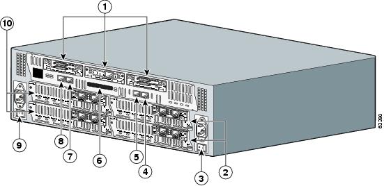
Figure 7 shows the back panel of the Cisco 3745 with:
•
•
•
Note
–
–
–
Figure 7 Cisco 3745 Back Panel
Interface card slots
Cisco 3700 Compact Flash slot
Network modules
Auxiliary port
Power supply
Console port
FastEthernet 0/0
Power supply
FastEthernet 0/1
Network modules
Voice Interface Numbering
Voice interfaces are numbered differently from the WAN interfaces described in the previous section. Voice interfaces are numbered as follows:
network-module-slot/voice-module-slot/voice-interface
If a 4-channel voice network module is installed in chassis slot 1, the voice interfaces are:
•
•
•
•
8 Where to Go Next
For additional detailed configuration procedures, refer to the appropriate Cisco 3700 series documentation or Cisco IOS software documentation, available on-line on Cisco.com.
Tip
To access documentation on Cisco.com:
For Cisco 3700 series platform documentation, start at Cisco.com at http://www.cisco.com, and select Products & Services > Routers > Cisco 3700 Series Multiservice Platforms > Technical Documentation > Document type > Document.
For Cisco IOS software documentation, start at Cisco.com at http://www.cisco.com, and select Products & Services > IOS Software > Cisco IOS Software Releases > Your Cisco IOS software release.
To get updated information about platform support for features, select Feature Navigator II, if you have an account on Cisco.com. You can also access Feature Navigator II at http://www.cisco.com/go/fn.
To access documentation using Cisco Connection Online (CCO):
For Cisco 3745 platform documentation, start at Cisco.com at http://www.cisco.com, and click the "Technical Documentation" tab under Useful Links. Under the Product Documentation heading, navigate to Modular Access Routers and to the documentation for your router.
For Cisco IOS software documentation, start at Cisco.com at http://www.cisco.com, and click the "Technical Documentation" tab under Useful Links. Under the Product Documentation heading, navigate to the Cisco IOS software documentation for the Cisco IOS software release that is installed on your router.
9 Obtaining Documentation
Cisco documentation and additional literature are available on Cisco.com. This section explains the product documentation resources that Cisco offers.
Cisco.com
You can access the most current Cisco documentation at this URL:
http://www.cisco.com/techsupport
You can access the Cisco website at this URL:
You can access international Cisco websites at this URL:
http://www.cisco.com/public/countries_languages.shtml
Product Documentation DVD
The Product Documentation DVD is a library of technical product documentation on a portable medium. The DVD enables you to access installation, configuration, and command guides for Cisco hardware and software products. With the DVD, you have access to the HTML documentation and some of the PDF files found on the Cisco website at this URL:
http://www.cisco.com/univercd/home/home.htm
The Product Documentation DVD is created monthly and is released in the middle of the month. DVDs are available singly or by subscription. Registered Cisco.com users can order a Product Documentation DVD (product number DOC-DOCDVD= or DOC-DOCDVD=SUB) from Cisco Marketplace at the Product Documentation Store at this URL:
http://www.cisco.com/go/marketplace/docstore
Ordering Documentation
You must be a registered Cisco.com user to access Cisco Marketplace. Registered users may order Cisco documentation at the Product Documentation Store at this URL:
http://www.cisco.com/go/marketplace/docstore
If you do not have a user ID or password, you can register at this URL:
http://tools.cisco.com/RPF/register/register.do
10 Documentation Feedback
You can provide feedback about Cisco technical documentation on the Cisco Technical Support & Documentation site area by entering your comments in the feedback form available in every online document.
11 Cisco Product Security Overview
Cisco provides a free online Security Vulnerability Policy portal at this URL:
http://www.cisco.com/en/US/products/products_security_vulnerability_policy.html
From this site, you will find information about how to do the following:
•
•
•
A current list of security advisories, security notices, and security responses for Cisco products is available at this URL:
To see security advisories, security notices, and security responses as they are updated in real time, you can subscribe to the Product Security Incident Response Team Really Simple Syndication (PSIRT RSS) feed. Information about how to subscribe to the PSIRT RSS feed is found at this URL:
http://www.cisco.com/en/US/products/products_psirt_rss_feed.html
Reporting Security Problems in Cisco Products
Cisco is committed to delivering secure products. We test our products internally before we release them, and we strive to correct all vulnerabilities quickly. If you think that you have identified a vulnerability in a Cisco product, contact PSIRT:
•
An emergency is either a condition in which a system is under active attack or a condition for which a severe and urgent security vulnerability should be reported. All other conditions are considered nonemergencies.
•
In an emergency, you can also reach PSIRT by telephone:
•
•
Tip
Never use a revoked encryption key or an expired encryption key. The correct public key to use in your correspondence with PSIRT is the one linked in the Contact Summary section of the Security Vulnerability Policy page at this URL:
http://www.cisco.com/en/US/products/products_security_vulnerability_policy.html
The link on this page has the current PGP key ID in use.
If you do not have or use PGP, contact PSIRT to find other means of encrypting the data before sending any sensitive material.
12 Product Alerts and Field Notices
Modifications to or updates about Cisco products are announced in Cisco Product Alerts and Cisco Field Notices. You can receive Cisco Product Alerts and Cisco Field Notices by using the Product Alert Tool on Cisco.com. This tool enables you to create a profile and choose those products for which you want to receive information.
To access the Product Alert Tool, you must be a registered Cisco.com user. (To register as a Cisco.com user, go to this URL: http://tools.cisco.com/RPF/register/register.do) Registered users can access the tool at this URL: http://tools.cisco.com/Support/PAT/do/ViewMyProfiles.do?local=en
13 Obtaining Technical Assistance
Cisco Technical Support provides 24-hour-a-day award-winning technical assistance. The Cisco Technical Support & Documentation website on Cisco.com features extensive online support resources. In addition, if you have a valid Cisco service contract, Cisco Technical Assistance Center (TAC) engineers provide telephone support. If you do not have a valid Cisco service contract, contact your reseller.
Cisco Technical Support & Documentation Website
The Cisco Technical Support & Documentation website provides online documents and tools for troubleshooting and resolving technical issues with Cisco products and technologies. The website is available 24 hours a day at this URL:
http://www.cisco.com/techsupport
Access to all tools on the Cisco Technical Support & Documentation website requires a Cisco.com user ID and password. If you have a valid service contract but do not have a user ID or password, you can register at this URL:
http://tools.cisco.com/RPF/register/register.do
Note
Tip
If you suspect that the browser is not refreshing a web page, force the browser to update the web page by holding down the Ctrl key while pressing F5.
To find technical information, narrow your search to look in technical documentation, not the entire Cisco.com website. On the Cisco.com home page, click the Advanced Search link under the Search box and then click the Technical Support & Documentation.radio button.
To provide feedback about the Cisco.com website or a particular technical document, click Contacts & Feedback at the top of any Cisco.com web page.
Submitting a Service Request
Using the online TAC Service Request Tool is the fastest way to open S3 and S4 service requests. (S3 and S4 service requests are those in which your network is minimally impaired or for which you require product information.) After you describe your situation, the TAC Service Request Tool provides recommended solutions. If your issue is not resolved using the recommended resources, your service request is assigned to a Cisco engineer. The TAC Service Request Tool is located at this URL:
http://www.cisco.com/techsupport/servicerequest
For S1 or S2 service requests, or if you do not have Internet access, contact the Cisco TAC by telephone. (S1 or S2 service requests are those in which your production network is down or severely degraded.) Cisco engineers are assigned immediately to S1 and S2 service requests to help keep your business operations running smoothly.
To open a service request by telephone, use one of the following numbers:
Asia-Pacific: +61 2 8446 7411
Australia: 1 800 805 227
EMEA: +32 2 704 55 55
USA: 1 800 553 2447For a complete list of Cisco TAC contacts, go to this URL:
http://www.cisco.com/techsupport/contacts
Definitions of Service Request Severity
To ensure that all service requests are reported in a standard format, Cisco has established severity definitions.
Severity 1 (S1)—An existing network is "down" or there is a critical impact to your business operations. You and Cisco will commit all necessary resources around the clock to resolve the situation.
Severity 2 (S2)—Operation of an existing network is severely degraded, or significant aspects of your business operations are negatively affected by inadequate performance of Cisco products. You and Cisco will commit full-time resources during normal business hours to resolve the situation.
Severity 3 (S3)—Operational performance of the network is impaired while most business operations remain functional. You and Cisco will commit resources during normal business hours to restore service to satisfactory levels.
Severity 4 (S4)—You require information or assistance with Cisco product capabilities, installation, or configuration. There is little or no effect on your business operations.
14 Obtaining Additional Publications and Information
Information about Cisco products, technologies, and network solutions is available from various online and printed sources.
•
•
http://www.cisco.com/go/marketplace/
•
•
•
http://www.cisco.com/en/US/products/index.html
•
http://www.cisco.com/discuss/networking
•
http://www.cisco.com/univercd/cc/td/doc/abtunicd/136957.htm
•
http://www.cisco.com/en/US/learning/index.html